IFHNEON7272 MHz Remote Control Transmitter
Hitec RCD Inc.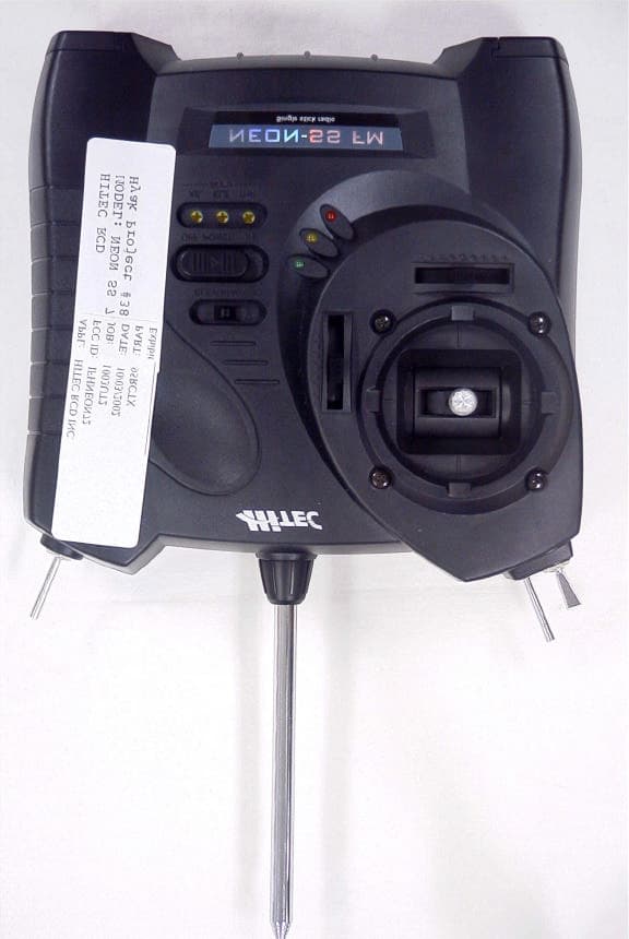
Click to zoom
Application Details
- Equipment Class
- TNB - Licensed Non-Broadcast Station Transmitter
- Date of Grant
- Nov 25, 2002
- Application Purpose
- Original Equipment
- Date of Application
- Nov 25, 2002
- Equipment Note
- 72 MHz Remote Control Transmitter
- Frequency Range
- 72.01000000 - 72.99000000
- Company
- Hitec RCD Inc.
- Country
- United States
Documents & Files
Document Text
Text extracted from the exhibit documents filed with the FCC. Open a document above to read the original.
Users Manual
Austria, Belgium, Denmark, Finland, France, Germany, Greece, Iceland, Ireland, The Netherland, Italy, Spain, Norway, Portugal, United Kingdom, Luxembourg, Sweden, Switzerland www.hitecrcd.com www.hitecrcd.com NEON-SS FM INSTRUCTION MANUAL 4th ch. Switch Use: The Neon has an optional 4th channel, three position switch available for a variety of functions including flap or spoiler deployment, bomb drop mechanisms and retracts. Installation: (#54301) Remove the Transmitter antenna Remove the back half of the case Install the 4th Ch. Switch and connect the wires to the main board (see picture) Re-assemble 23 1 Introduction Congratulations, you now own one of the most unique and revolutionary radio control systems in the world. The Neon 3 was created for the beginner and seasoned R/C enthusiast to grow with your needs and skill level. The basic Neon can be upgraded with a variety of features like; - A 4th channel two position switch - Dual Rates - ATV's on ch. 1 and 2 - A trainer port and switch package Any way you customize the Neon, we are sure you will be satisfied with the performance of the radio system. Good luck and good flying! 2 Features and Specifications: Transmitter Single Stick 3 channel, (upgradeable to 4 channel) FM proportional system Dual axis precision gimbal Adjustable gimbal stick length Adjustable gimbal stick tension 3 LED battery status indicators Charging jack for internal Nicad battery Servo reversing function for channels 1, 2, 3 and 4 Elevon or V-tail mixing function Proportional 3rd. channel slide switch Channel 1 and 2 trim levers Options - Channel 4 three position switch, part # 54301 - Channel 1,2 and 3 ATV function. part # 54302 - Trainer plug and switch, part # 54303 - Channel 1 and 2 Dual Rate function # 54304 (must use optional part 54304, ATV function, in addition to this option) System Components Receiver Standard version includes Electron 6 channel Dual Conversion 6 channel FM receiver Micro version includes HFS-04MG 4 channel Single Conversion 4 channel FM receiver Servo Standard version includes two HS-81 micro servos Micro version includes two HS-55 sub-micro servos Accessories, all systems One CG-25 or CG-22A overnight wall charger, part # 43025 or # 43022 One Switch harness, part # 54403 One AAA receiver battery box, part # 54402 3 Set-up and Operation Transmitter Opening the case The case of your Neon is unique because it does not have the traditional screws holding it together. Instead we have created a "pull apart" case to facilitate access to the inside components. To open your case, slide the tabs located at the bottom corners off and gently pull the bezel at the base of the antenna up. Now separate the two case half's while being careful of the internal wiring harness to the throttle switch, unplug the wires leading to the throttle switch, and you can now access the internal components to add optional feature packages, reverse your servos, or change the battery out. - Size: 45.5 x 22.5 x 15.0 (mm) / 1.79 x 0.88 x 0.59 (inch) - Weight :17g(0.6oz) without X-tal / 13g(0.4oz) without case - Size: 25 x 37.5 x 16 (mm) / 0.98 x 1.47 x 0.62 (inch) - Weight : 15.9 - Speed : .17(4.8V) /.14sec(6.0V) - Torque : 1.1(kg/cm) / 15oz at 4.8V 1.3(kg/cm) /18oz at 4.8V - Size : 23 x 12 x 24(mm) / 0.90 x 0.45 x 0.94(inch) - Weight : .28oz/8.0g - Speed : .11(4.8V) /.10sec(6.0V) - Torque : 2.6(kg/cm) / 36oz at 4.8V 3.0(kg/cm) / 42oz at 6.0V - Size : 30 x 12 x 30(mm) / 1.2 x 0.47 x 1.2(inch) - Weight : .58oz/16.6g OPEN OPEN 23 1 Introduction Congratulations, you now own one of the most unique and revolutionary radio control systems in the world. The Neon 3 was created for the beginner and seasoned R/C enthusiast to grow with your needs and skill level. The basic Neon can be upgraded with a variety of features like; - A 4th channel two position switch - Dual Rates - ATV's on ch. 1 and 2 - A trainer port and switch package Any way you customize the Neon, we are sure you will be satisfied with the performance of the radio system. Good luck and good flying! 2 Features and Specifications: Transmitter Single Stick 3 channel, (upgradeable to 4 channel) FM proportional system Dual axis precision gimbal Adjustable gimbal stick length Adjustable gimbal stick tension 3 LED battery status indicators Charging jack for internal Nicad battery Servo reversing function for channels 1, 2, 3 and 4 Elevon or V-tail mixing function Proportional 3rd. channel slide switch Channel 1 and 2 trim levers Options - Channel 4 three position switch, part # 54301 - Channel 1,2 and 3 ATV function. part # 54302 - Trainer plug and switch, part # 54303 - Channel 1 and 2 Dual Rate function # 54304 (must use optional part 54304, ATV function, in addition to this option) System Components Receiver Standard version includes Electron 6 channel Dual Conversion 6 channel FM receiver Micro version includes HFS-04MG 4 channel Single Conversion 4 channel FM receiver Servo Standard version includes two HS-81 micro servos Micro version includes two HS-55 sub-micro servos Accessories, all systems One CG-25 or CG-22A overnight wall charger, part # 43025 or # 43022 One Switch harness, part # 54403 One AAA receiver battery box, part # 54402 3 Set-up and Operation Transmitter Opening the case The case of your Neon is unique because it does not have the traditional screws holding it together. Instead we have created a "pull apart" case to facilitate access to the inside components. To open your case, slide the tabs located at the bottom corners off and gently pull the bezel at the base of the antenna up. Now separate the two case half's while being careful of the internal wiring harness to the throttle switch, unplug the wires leading to the throttle switch, and you can now access the internal components to add optional feature packages, reverse your servos, or change the battery out. - Size: 45.5 x 22.5 x 15.0 (mm) / 1.79 x 0.88 x 0.59 (inch) - Weight :17g(0.6oz) without X-tal / 13g(0.4oz) without case - Size: 25 x 37.5…
Text truncated - open the document above for the full version.
ID Label/Location Info
FCC ID: IFHNEON72 Model Neon SS 72MHz
Operational Description
4 Tuning Procedures 1.Attach 12.0 Vdc power supply 2.Using a Modulation Meter, adjust VR8 until proper modulation is displayed. 3.Using a Frequency Counter, Adjust VR9 until proper frequency is displayed. 4.Repeat steps 2 and 3 5.Using a Spectrum analyzer and a short-range pick-up antenna, look for 72MHz signal with sufficient scan width to see 30-150 MHz spurious. 6.Adjust T1, T2, T3, T4, and T5 for maximum output at operating frequency and minimum output at any harmonics. 7.Repeat step 6. 8.Check for minimum emissions from 30 to 760 MHz. Inspection Specifications Frequency: UP 1K +/- 500Hz Modulation: NEG. 2.8K +/- .3K RF Power: 350 +/- 50mW Frame Time: 20~24mS General Description The Neon is a low power, non-voice, transmitter intended for remote control of model aircraft in the 72MHz band. The unit is held with two hands in front of the body. The equipment employs a vertical polarized antenna, directly mounted on the unit and meets Paragraphs 95.645, 95.647, 95.649, and the technical requirements established in the Report & Order in PR Docket 90-222. Circuits and Devices to Stabilize Frequency Transmitter output frequency is determined and stabilized by crystal-controlled oscillator. Circuits to suppress Spurious Radiation Final RF amplifier spurious emissions are attenuated by a “PI” matching network consisting of L3, L2, C86, C89, C89, C90, C91, C92, C93, T4 and T5. Functions of Active Semiconductors Reference Type Function Q4 C1623 Buffer/SW Q5 C1623 Modulator Q6 C2223 Driver/ X-Tal Oscillator Q7 C2223 Driver Q8 C4910 Final Amplifier IC1 GMS87C1202 Encoder
Parts List/Tune Up Info
4 Tuning Procedures 1.Attach 12.0 Vdc power supply 2.Using a Modulation Meter, adjust VR8 until proper modulation is displayed. 3.Using a Frequency Counter, Adjust VR9 until proper frequency is displayed. 4.Repeat steps 2 and 3 5.Using a Spectrum analyzer and a short-range pick-up antenna, look for 72MHz signal with sufficient scan width to see 30-150 MHz spurious. 6.Adjust T1, T2, T3, T4, and T5 for maximum output at operating frequency and minimum output at any harmonics. 7.Repeat step 6. 8.Check for minimum emissions from 30 to 760 MHz. Inspection Specifications Frequency: UP 1K +/- 500Hz Modulation: NEG. 2.8K +/- .3K RF Power: 350 +/- 50mW Frame Time: 20~24mS General Description The Neon is a low power, non-voice, transmitter intended for remote control of model aircraft in the 72MHz band. The unit is held with two hands in front of the body. The equipment employs a vertical polarized antenna, directly mounted on the unit and meets Paragraphs 95.645, 95.647, 95.649, and the technical requirements established in the Report & Order in PR Docket 90-222. Circuits and Devices to Stabilize Frequency Transmitter output frequency is determined and stabilized by crystal-controlled oscillator. Circuits to suppress Spurious Radiation Final RF amplifier spurious emissions are attenuated by a “PI” matching network consisting of L3, L2, C86, C89, C89, C90, C91, C92, C93, T4 and T5. Functions of Active Semiconductors Reference Type Function Q4 C1623 Buffer/SW Q5 C1623 Modulator Q6 C2223 Driver/ X-Tal Oscillator Q7 C2223 Driver Q8 C4910 Final Amplifier IC1 GMS87C1202 Encoder
Test Report
APPLICANT: HITEC RCD INC. FCC ID: IFHNEON72 REPORT #: H\HITEC\1003UT2\1003UT2TestReport.doc TABLE OF CONTENTS TABLE OF CONTENTS LIST APPLICANT: HITEC RCD INC. FCC ID: IFHNEON72 TEST REPORT: PAGE 1......COVER SHEET - GENERAL INFORMATION & TECHNICAL DESCR. PAGE 2......TECHNICAL DESCRIP. CONTINUED. & RF POWER OUTPUT PAGE 3......MODULATION CHARACTERISTICS AND OCCUPIED BANDWIDTH PAGE 4......OCCUPIED BANDWIDTH PLOT PAGE 5......OCCUPIED BANDWIDTH PLOT - CW PAGE 6......FIELD STRENGTH OF SPURIOUS EMISSION PAGE 7......METHOD OF MEASURING RADIATED SPURIOUS EMISSIONS PAGE 8......FREQUENCY STABILITY PAGE 9-12...TEST EQUIPMENT LIST EXHIBIT CONTAINING: EXHIBIT 1..........FCC ID LABEL SAMPLE & LOCATION EXHIBIT 2..........EXTERNAL PHOTOGRAPHS EXHIBIT 3..........INTERNAL PHOTOGRAPHS EXHIBIT 4..........SCHEMATIC EXHIBIT 5..........USER'S MANUAL EXHIBIT 6..........CIRCUIT DESCRIPTION EXHIBIT 7..........TUNING PROCEDURE EXHIBIT 8..........TEST SET UP PHOTO APPLICANT: HITEC RCD INC. FCC ID: IFHNEON72 REPORT #: H\HITEC\1003UT2\1003UT2TestReport.doc Page 1 of 12 GENERAL INFORMATION 2.1033(c)(1)(2) HITEC RCD INC.will sell the FCCID: IFHNEON72 Radio Control transmitter in quantity, for use under FCC RULES PART 95 SUBPART C. HITEC RCD INC. 12115 PAINE STREET POWAY, CA 92064 2.1033(c)(3) Instruction manual is included as exhibit #5. 2.1033 (4) Type of Emission: 8K0F1D 95.631(b)(1) Bn = 2M + 2DK M = 4,800 Bits per second D = 800 Hz (Peak Deviation) K = 1 Bn = 2(4800/2) + 2(800)(1) = 4.8K + 3.2K = 8.0k ALLOWED AUTHORIZED BANDWIDTH = 8.00 kHz. 95.631(b) Authorized Bandwidth 8 kHz for RC Transmitter 2.1033(c)(5) Frequency Range: 72.01-72.99 MHz 95.623(a) (6) Power Range and Controls: There are NO user Power controls. (6) Function of each electron tube or semiconductor device or other active circuit device: See Exhibit #6. (7) Maximum Output Power Rating: 0.3 W ERP. (8) DC Voltages and Current into Final Amplifier: FINAL AMPLIFIER ONLY Vce = 12.0Volts DC Ice = 0.039A. Pin = 0.5Watts 2.1033(c)(9) Tune-up procedure. The tune-up procedure is included as Exhibit #7. APPLICANT: HITEC RCD INC. FCC ID: IFHNEON72 REPORT #: H\HITEC\1003UT2\1003UT2TestReport.doc Page 2 of 12 2.1033(c)(10) Complete Circuit Diagrams: The circuit diagram is included as part of Exhibit # 4. (10) Description of all circuitry and devices provided for determining and stabilizing frequency is given in EXHIBIT #6. 2.1033(c)(11) The Equipment identification is shown as Exhibit #1. 2.1033(c)(12) Photographs of the equipment are shown as Exhibits No. 2-3. 2.1033(c)(13) Equipment employing Digital modulation. N/A. 2.1033(c)(14) The data required by 2.1046-2.1057 follows; 2.1046 RF power is measured by the ERP METHOD. There is no provisions to limit the power. With a nominal battery voltage of 12.0 VDC, and the transmitter properly adjusted the RF output measures: Po = 0.3 Watts ERP 2.1046 RF power output. HP Spectrum Analyzer TRANSMITTER UNDER TEST WITH INTERNAL ANTENNA 3.0 meters SIGNAL DIPOLE Tuned, Calibrated GENERATOR ANTENNA Antenna which may be raised from 1 to 4 meters above ground and changed in polarization Equipment placed 80 cm. above ground on a rotatable platform. APPLICANT: HITEC RCD INC. FCC ID: IFHNEON72 REPORT #: H\HITEC\1003UT2\1003UT2TestReport.doc Page 3 of 12 2.1047 Modulation characteristics: AUDIO FREQUENCY RESPONSE The Voice is NOT allowed in this band. 2.1049 Occupied bandwidth: 95.635(b) (1) At least 25dB on any frequency removed from the center of the authorized bandwith by more than 50% up to and including 100% of the authorized bandwidth. (10) At least 45 dB on any frequency removed from the center of the authorized bandwidth by more than 100% up to and including 125% of the authorized bandwidth. (11) At least 55 dB on any frequency removed from the center of the authorized bandwidth by more than 125% up to and including 250% of the authorized bandwidth. (12) At least 56 + 10 log 10 (T) dB on any frequency removed from the center of the authorized bandwidth by more than 250%. Radiotelephone transmitter with modulation limiter. Test procedure diagram OCCUPIED BANDWIDTH MEASUREMENT Coupler Transmitter 50 ohm under test Resistive Wattmeter Audio Spectrum Oscillator Analyzer APPLICANT: HITEC RCD INC. FCC ID: IFHNEON72 REPORT #: H\HITEC\1003UT2\1003UT2TestReport.doc Page 4 of 12 OCCUPIED BANDWIDTH PLOT APPLICANT: HITEC RCD INC. FCC ID: IFHNEON72 REPORT #: H\HITEC\1003UT2\1003UT2TestReport.doc Page 5 of 12 OCCUPIED BANDWIDTH PLOT – CW APPLICANT: HITEC RCD INC. FCC ID: IFHNEON72 REPORT #: H\HITEC\1003UT2\1003UT2TestReport.doc Page 6 of 12 2.1051 SPURIOUS EMISSIONS AT ANTENNA TERMINALS. NOT APPLICABLE, NO antenna port. This UUT has a permanently attached antenna. 2.1053 UNWANTED RADIATION: 95.635(1)(3)(7)(10)(11)(12) REQUIREMENTS: At least 56 + 10log(T) on any frequency removed from the center of the authorized bandwidth by more than 250%. 56 + 10log(0.3) = 51 dB TEST DATA: Emission Frequency MHz ATTN dBc dBm Margin dB 72.74 0.00 24.80 0.00 145.48 62 -37 11.00 218.10 67 -42 16.00 290.91 76 -51 25.00 363.62 76 -51 25.00 436.31 72 -47 21.00 509.05 73 -48 22.00 581.74 65 -40 14.00 654.44 79 -54 28.00 727.20 71 -46 20.00 METHOD OF MEASUREMENT: The procedure used was C63.4-1992. The unit was operating into its permanently attached antenna at a height of 80 cm. The spectrum was scanned from 30 to at least the tenth haromonic of the fundamental using a HP model 8566B spectrum analyzer and an appropriate antenna. Measurements were made at the open field test site of TIMCO ENGINEERING INC. located at 849 N.W. State Road 45 Newberry, FL 32669. APPLICANT: HITEC RCD INC. FCC ID: IFHNEON72 REPORT #: H\HITEC\1003UT2\1003UT2TestReport.doc Page 7 of 12 Method of Measuring Radiated Spurious Emissions Hewlett Packard Spectrum Analyzer HP8566B TRANSMITTER _____ INTEGRAL ANTENNA UNDER TEST <- 3.0m > Tuned, Calibrated Antenna which may be raised from 1m to 4m above ground POWER SUPPLY and changed in polarization Equipment placed 80cm above ground on a rotatab…
Text truncated - open the document above for the full version.
Contact Information
Applicant
Tony Ohm(Service Dept. Manager)
Test Firm
Timco Engineering, Inc.S Sanders
Technical Specifications
| # | Rule Parts | Frequency Range | Power Output | Emission | Tolerance |
|---|---|---|---|---|---|
| 1 | 95C | 72.01 MHz - 72.99 MHz | 300.00 mW | 8K00F1D | 20.0000000000 ppm |
Other Applications from Hitec RCD Inc.
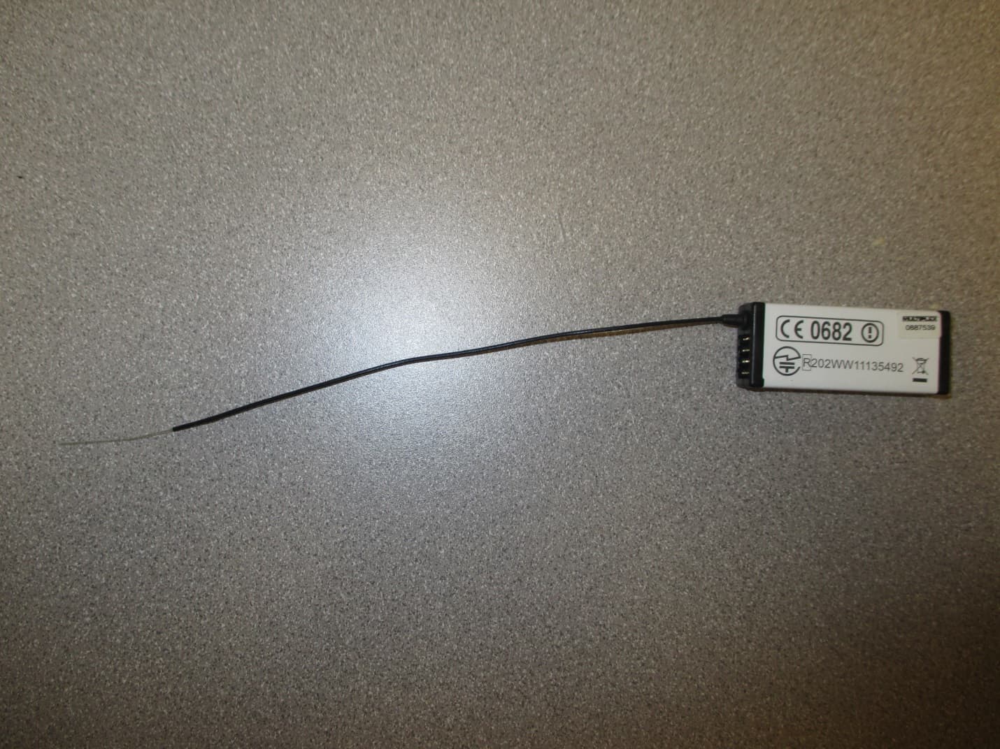
IFHRX57MLINK
Dec 22, 20147 CHANNEL 2.4 GHz TRANSCEIVER
Equipment Class
DSS - Part 15 Spread Spectrum Transmitter
IFHRX5MLINK
Dec 16, 2014RX5 M-LINK CHANNEL 2.4 GHz TRANSCEIVER
Equipment Class
DXX - Part 15 Low Power Communication Device Transmitter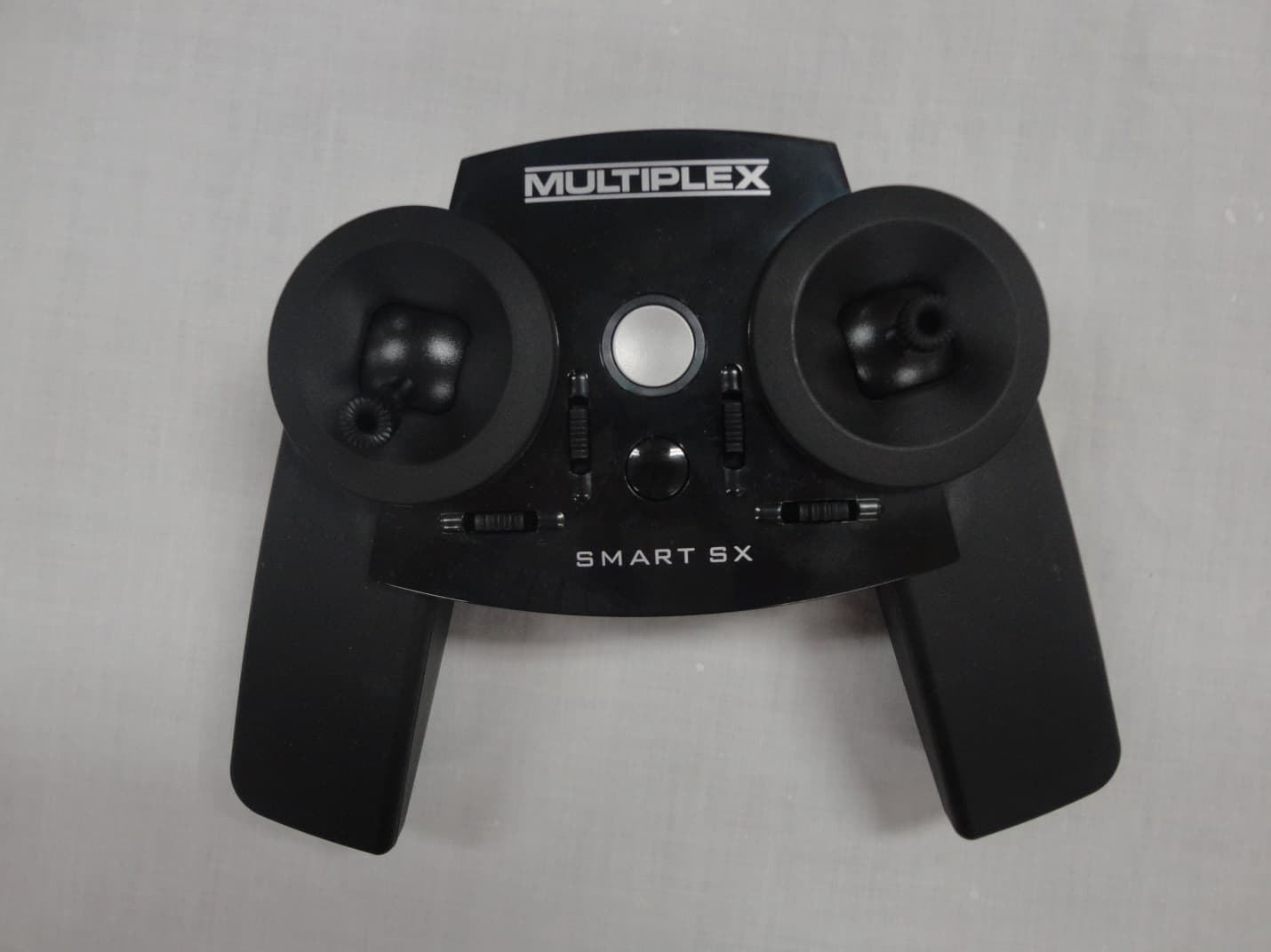
IFHSMART-SX
Sep 16, 20146 CHANNEL 2.4 GHz RADIO CONTROL TRANSMITTER
Equipment Class
DSS - Part 15 Spread Spectrum Transmitter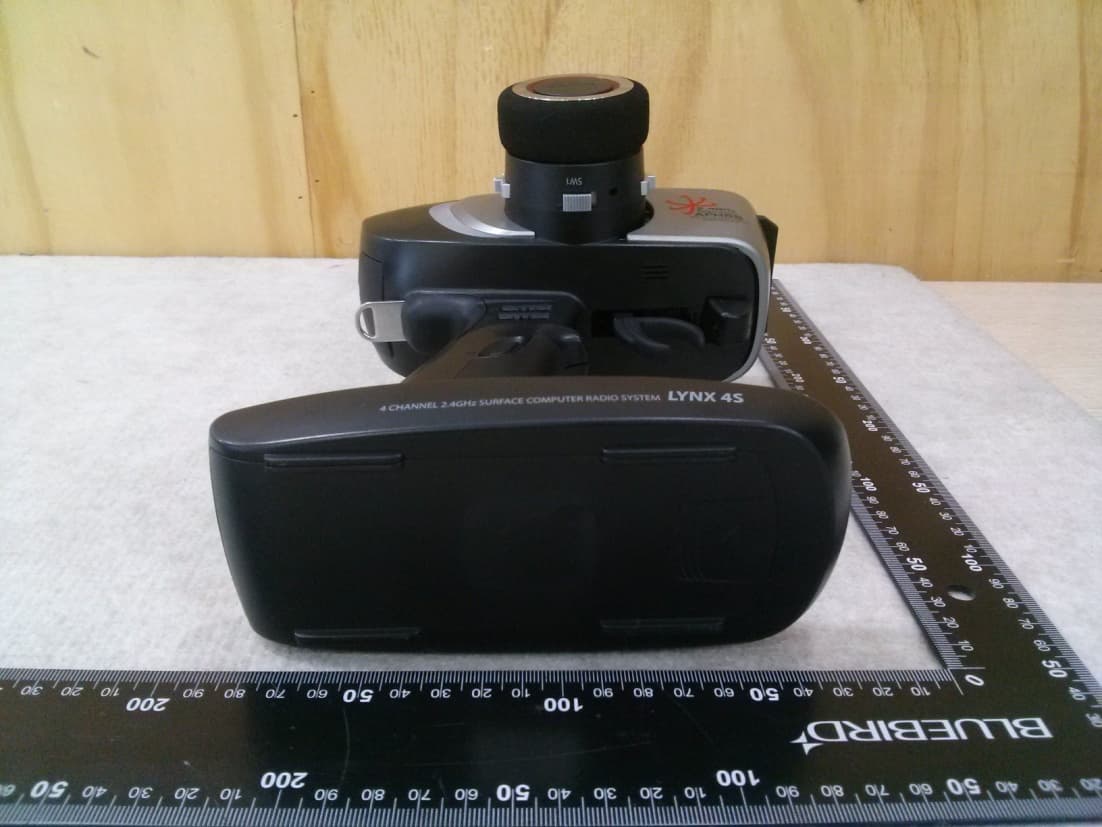
IFHLYNX4S
Jul 22, 20142.4GHz Radio Control System
Equipment Class
DSS - Part 15 Spread Spectrum Transmitter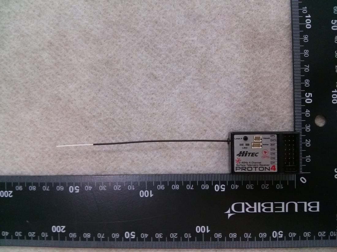
IFHPROTON4
Jul 22, 20142.4GHz Radio Control System
Equipment Class
DSS - Part 15 Spread Spectrum Transmitter