IFHOPT5-24G2.4GHz RADIO CONTROL SYSTEM
Hitec RCD Inc.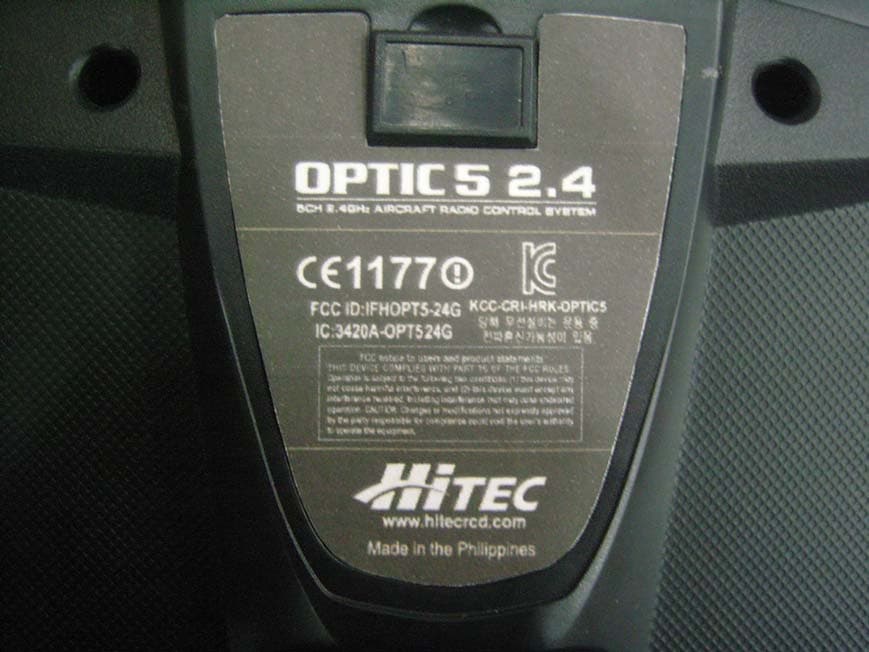
Click to zoom
Application Details
- Equipment Class
- DSS - Part 15 Spread Spectrum Transmitter
- Date of Grant
- Mar 27, 2011
- Application Purpose
- Original Equipment
- Date of Application
- Mar 23, 2011
- Equipment Note
- 2.4GHz RADIO CONTROL SYSTEM
- Frequency Range
- 2405.60000000 - 2477.60000000
- Company
- Hitec RCD Inc.
- Country
- United States
Documents & Files
Document Text
Text extracted from the exhibit documents filed with the FCC. Open a document above to read the original.
Users Manual
OPTIC5 2.4 USER MANUAL Hitec RCD INC. Introducing the Optic 5 2.4 Congratulations and welcome to the R/C world! You now own a basic, but unusually versatile and powerful, 5-Channel beginner’s RC transmitter. The Optic 5 2.4 is all the radio you need to fly the most of 5-Channel fixed-wings aircraft models. Standard features include servo-reversing for all channels, trim adjustments on all control channels, ATV (Adjustable Travel Volume) on Aileron (CH.1) and Elevator (CH.2). The Optic 5 2.4 features: Pre-mixed Flight Control Functions: The Optic 5 2.4 computer automatically mixes rudder and elevator outputs to control a V-tail or mixes aileron and elevator outputs to create elevons for tail-less flying wings, eliminating the need for on- board mixing systems. Trim Adjustment Function: This computerized radio allows you to easily tune and coordinate the control surfaces (such as keeping a rudder centered or two ailerons-each on their own servo-moving the same amount) without having to physically re-adjust linkages. Buddy-Box Function: For those learning to fly, the transmitter has a "buddy-box" capability so that you can use the optional trainer cord to connect your Optic 5 2.4 to another Hitec transmitter (Master)*. This function allows one transmitter to be used by an instructor as the primary flight control while the other is controlled by the student pilot. *Note: Optic 5 2.4 only can be used as a Pupil (Slave) transmitter. If you are new to Computerized RC Transmitters If OPTIC 5 2.4 is your first radio control transmitter, you're probably feeling a bit overwhelmed. However, if you take little time to read this manual and follow the programming steps as you watch your model's control surfaces respond, handling the Optic 5 2.4 will soon become quite comfortable. So stick with it. Learning the programming basics won't take any longer or require any more brain power than it takes to do the average crossword or Sudoku puzzle. You'll discover that the rewards for mastering this simple radio are well worth the effort. TIP: Throughout the manual you will see our "Tip Sheet" notes. These highlight specific function details we didn't want you to miss within the body of the manual. Check these out; they can make programming the Optic Sport easier. Hitec AFHSS 2.4GHz Technology Most of Hitec’s 2.4GHz product uses AFHSS (Advanced Frequency Hopping Spread Spectrum) technology which gives you highly stable one-way and telemetric signals for ensure safe flight of your model aircrafts. Equipment Mounting When you mount each servo, use the supplied rubber grommets and insert an eyelet up through the bottom. Be sure not to over tighten the screws. If any portion of the servo case directly contacts the fuselage or the servo rails, the rubber grommets will not be able to attenuate vibration, which can lead to mechanical wear and possible servo failure. Servo Throw Once you have installed the servos, operate each one over its full travel and check that the pushrod and output arms do not bind or collide with each other, even at extreme trim settings. Check to see that each control linkage does not require undue force to move (if you hear a servo buzzing when there is no transmitter control motion, most likely there is too much friction in the control or pushrod). Even though the servo will tolerate loads like this, they will drain the battery pack much more rapidly Receiver Installation and Setup Note: Vibration and Water The receiver contains precision electronic parts. Be sure to avoid vibration, shock, and temperature extremes. For protection, wrap the receiver in the provided "Flight Preserver" foam rubber, or use some other vibration-absorbing materials. If you are flying near bodies of water, it's also a good idea to protect the receiver by placing it in a plastic bag and securing the open end of the bag with a rubber band before wrapping it with foam. If you accidentally get moisture inside the receiver, you may experience intermittent operation or a crash. Switch Harness Installation When you are ready to install the receiver's switch harness, remove the switch cover and use it as a template to cut screw holes and a rectangular hole slightly larger than the full stroke of the switch. Choose a switch location on the opposite side of the fuselage from the engine exhaust, and choose a location where it can't be inadvertently turned on or off during handling or storage. Install the switch so that it moves without restriction and "snaps" from ON to OFF and vice versa. M-BODA (Mini Boosted Omni-Directional Antenna) Installation You may run the antenna inside of a non-metallic housing within the fuselage (a plastic outer pushrod housing works well for this), but range may suffer if the antenna is located near metal pushrods or cables. Be sure to perform a range check before flying. With the 2.4GHz radio system, the range check method is different from the conventional frequency radio system. During the range check period, you should be able to walk away at least 75 feet from the model without losing control or seeing "jitter" in the servos. The range check should be done with the motor running and the model should be securely restrained in case of loss of control. Connectors Be sure the alignment of a servo or battery connector is correct before inserting it into the receiver. To remove a connector from the receiver, try to pull on the connector's plastic housing rather than pulling on the wires. Pulling the wires can ruin the connector pins and break wires. Using Servo Wire Extensions If any of your servos are located too far away to plug directly into the receiver (like the aileron servo), or you need to unplug the servo each time you disassemble the model, use a servo extension cord to extend the length of the servo lead. Additional Hitec extension cords of varying lengths are available from your hobby dealer. Charge the Batteries! Before we dive into the use of the Optic 5 2.4, let's charge the batte…
Text truncated - open the document above for the full version.
Cover Letter(s)
FCC, Request for non-disclosureDate: March 09, 2011 Page 1 of 1 Hitec RCD Inc. 12115 Paine Street, Poway California, United States Subject:Request for confidentiality FCC ID: IFHOPT5-24G Reference number: Dear FCC TCB, Persuant to 47 CFR Section 0.459(a) & (b), <name applicant> hereby requests non-disclosure and confidential treatment of the following materials submitted in support of FCC certification application for FCC ID: (IFHOPT5-24G) Bill(s) of Material☑ Block Diagrams☑ Operational Description☑ Schematic Diagrams☑ Above materials contain secrets, proprietary and technical information,whichwould customarily be quarded from competitors under 47 CFR, section 0.457(d)(2). Disclosure or publication or any portion of this company confidential material to otherparties could cause substantial competitive harm and provide unjustified benefits for competitors. <Name applicant> understands that pursuant to 47 CFR section 0.457(d)(1)(ii) disclosure of the applicant and all accompanying documentation will not be made before the date of the grant. <Date>March 09, 2011 <City> Poway, California <Nameandsignatureofapplicant> Tony Ohm / Service Dept. Manager
Cover Letter(s)
Hitec RCD Inc. 12115 Paine Street, Poway, California, United States November 25, 2010 Subject:DoC declaration To Whom it may concern, We, as the grantee of this project FCC ID: IFHOPT5-24G, would like to declare that the composite portion categorized as computer peripheral hasbeen authorized under the Declaration of Conformity procedures. Test Laboratory : Korea Standard Quality Laboratories #102, Jangduk Dong, Hwasung City, Kyunggi Do, South Korea Regards, Signature: Name/Title:Tony Ohm / Service Dept. Manager Company Name:Hitec RCD Inc. Address:12115 Paine Street, Poway, California, United States TEL:858-748-6948 FAX:858-748-1767 Email: [email protected]
External Photos
Photo 1: Exterior Photographs Top Bottom Side 1 Side 2 Side 3 Side 4 Label
ID Label/Location Info
Label Information 1. Label Location Label position 2. Label Drawing
Internal Photos
Interior view of EUT Internal Photos View of Main PCB(Top) View of Main PCB(Bottom) View of Module (Top) View of Sub 1 PCB(Top) View of Sub 1 PCB(Bottom) View of Sub 2 PCB(Top) View of Sub 2 PCB(Bottom) View of Sub 3 PCB(Top) View of Sub 3 PCB(Bottom) View of Sub 4 PCB(Top) View of Sub 4 PCB(Bottom) View of Sub 5 PCB(Top) View of Sub 5 PCB(Bottom) View of Sub 6 PCB(Top) View of Sub 6 PCB(Bottom)
Operational Description
CHIEF R&D DESIGN Daesik Hwang Jihyun Kim Hyunjung Kim Date June. 23. 09. SAE HAN ANTENNA CO.,LTD Specification for Approval Part name : WC-24Tx Antenna Part No : HTR24-001 TECHNICAL DATA SHEET Page 2 of 13 DIRECT FEED 1/2 WAVE DIPOLE FOR QUALIFICATION SaeHan Part Name WC-24Tx Series : Antenna NO Description Material 1 Mold Keyflex / Black 2 Ground Plane BsBM 3 Jonit A Nylon / Black 4 Pin BsBM / Black 5 Joint B Nylon / Black 6 Tube PVC / White 7 Bushing PVC / Black 8 Coaxial Cable PVC, Teflon, Cu, Plated Wire 9 ConnectorShell, Contact terminal : Phosphor Bronze, Insulator : PBT Series SPECIFICATION DRAWING TECHNICAL DATA SHEET Page 3 of 13 DIRECT FEED 1/2 WAVE DIPOLE FOR QUALIFICATION SaeHan Part Name WC-24Tx Series : Antenna Table of Contents ELECTRICAL CHARACTERISTICS MECHANICAL CHARACTERISTICS 1 General 1.1 Product description 1.2 Product Name 1.3 Units and Definitions 1.4 Conditions 2 ELECTRICAL PROPERTIES 2.1 Frequency Band 2.2 Impedance 2.3 V.S.W.R 2.4 Gain 3 MECHANICAL PROPERTIES 3.1 Tensile Load 3.2 Drop 3.3 Flexure 3.4 Tilt 4 ENVIRONMENTAL RESISTANCE PROPERTIES 4.1 Temperature 4.2 Humidity 4.3 Vibration TECHNICAL DATA SHEET Page 4 of 13 DIRECT FEED 1/2 WAVE DIPOLE FOR QUALIFICATION SaeHan Part Name WC-24Tx Series : Antenna ELECTRICAL CHARACTERISTICS . Center Frequency ................................................................ 2450 MHz . Frequency Range ................................................................. 2400~2500 MHz . Nominal Impedance ............................................................. 50 Ω (CF:2.45GHz) . VSWR.................................................................................... Less Than 2.0:1 . Type ..................................................................................... 1/2 wave dipole . Gain Peak Gain ........................................................................... 0.9 dBi . Radiation Pattern ................................................................... Omni Directional -3dB Beam width : . Horizontal Plane .................................................................... 360̊̊̊̊̊̋̊̊̊ ̊ . Vertical Plane ........................................................................ 85±10 ̊ . Polarization :........................................................................... Vertical . Maximum input power ........................................................... 3 W TECHNICAL DATA SHEET Page 5 of 13 DIRECT FEED 1/2 WAVE DIPOLE FOR QUALIFICATION SaeHan Part Name WC-24Tx Series : Antenna MECHANICAL CHARACTERISTICS Sleeve Material ............................................................ Keyflex /black Base & Cap Material: ................................................... Nylon / black Weight : ................................................................................. 8 g Connector type : ................................................................... U.FL Male (Micro Connector) Temperature : ....................................................................... -40/+85°C Sleeve Flexure (50 Cycles in 4 Orthogonal Directions).... +/-20° No Deformation Pull Force(Sleeve) ................................................................ 25 lbs Tilt Test ......................................................................... 90° Range 500Times Drop Test .............................................................................. 1m / 10Times Humidity ................................................................................ +30°C&95% RH 24Hours Vibration ................................................................................ Frequency 3-500-3Hz(1cycle) Sweep rate 5 db / octave Amplitude 1.12G-rms Acceleration 1.5g Sleeve Glue Material ............................................................ LOCTITE 401 Overall Length of Antenna .................................................. 105 mm +/- 0.5mm TECHNICAL DATA SHEET Page 6 of 13 DIRECT FEED 1/2 WAVE DIPOLE FOR QUALIFICATION SaeHan Part Name WC-24Tx Series : Antenna 1. GENERAL 1.1 Product description This antenna is to account for the measurement setup and results of 2.4GHz Type Dipole Antenna. 1.2 Product Name Saehan Antenna Product Name. : WC-24Tx Antenna 1.3 Units and Definitions V.S.W.R ................................ Voltage Standing Wave Ratio dBi ........................................ Antenna gain in dB relative to a isotropic antenna g ........................................... Acceleration of gravity(about 9.8 m/sec 2) RH.......................................... Relative Humidity Dimensions .......................... mm 1.4 Test Conditions Unless otherwise stated all temperature tolerance are ± 3°C and all RH tolerance are ± 5 percentage units Unless otherwise stated all values are valid at +20 °C and 50% RH 2. ELECTRICAL PROPERTIES 2.1 Frequency Band ..................................................... 2400 ~ 2500 MHz 2.2 Impedance ............................................................... Nominal Value : 50Ω 2.3 V S W R 2.3.1 Maximum Values ......................................... Less than 2.0 : 1 2.3.2 Measuring Method A 50ohms coaxial cable is connected to the antenna connector. In the other end the coaxial cable is connected to a network analyzer. The analyzer calibrated so that the reference plane is at the end the coaxial cable connected to the antenna TECHNICAL DATA SHEET Page 7 of 13 DIRECT FEED 1/2 WAVE DIPOLE FOR QUALIFICATION SaeHan Part Name WC-24Tx Series : Antenna FrequencyV.S.W.RRemarks 2.40GHz1.23 2.45GHz1.02 2.50GHz1.20 Figure 1. Network Analyzer Measuring V. S .W. R Figure 2. V. S. W. R Testing TECHNICAL DATA SHEET Page 8 of 13 DIRECT FEED 1/2 WAVE DIPOLE FOR QUALIFICATION SaeHan Part Name WC-24Tx Series : Antenna Chamber Size16(L)m X 11(W)m X 9.5(H)m Frequency Range 400MHz – 60GHz (Far Field) Quiet Zon 1.2m X 1.2 m @ 1GHz TypeRectangular 2.4 Gain 2.4.1 Measuring Method The connection is done according to figure. Radiation patters are measured at the lowest. middle and highest …
Text truncated - open the document above for the full version.
Test Report
Report Number : KSQ-FCC101208FCC ID : IFHOPT5-24G, IC : 3420A-OPT524G Page 3 /39 5.4.3 Test result......................................................................................................................................15 Table 3 : Measured values of the Power Spectral Density...............................................................................15 Figure 3 : Plot of the Power Spectral Density...............................................................................................16 5.5. CARRIER FREQUENCY SEPARATION........................................................................................18 5.5.1 Regulation.....................................................................................................................................18 5.5.2 Test Condition...............................................................................................................................18 5.5.3. Test result.....................................................................................................................................18 Table 4 : Measured values of the Carrier Frequency Separation.......................................................................18 Figure 4 : Plot of the Carrier Frequency Separation.......................................................................................19 5.6. NUMBEROF HOPPINGCHANNELS............................................................................................20 5.6.1 Regulation.....................................................................................................................................20 5.6.2 Test Condition...............................................................................................................................20 5.6.3 Test result......................................................................................................................................20 Table 5 : Measured values of the Number of Hopping Channels.......................................................................20 Figure 5 : Plot of the Number of Hopping Channels.......................................................................................21 5.7. TIMEOF OCCUPANCY(DWELLTIME).......................................................................................22 5.7.1 Regulation.....................................................................................................................................22 5.7.2 Test Condition...............................................................................................................................22 5.7.3 Test result......................................................................................................................................22 Table 6 : Measured values of the Dwell Time...............................................................................................22 Figure 6 : Plot of the Carrier Dwell Time....................................................................................................23 5.8. SPURIOUS EMISSIONS, BAND EDGE, AND RESTRICTED BANDS........................................25 5.8.1 Regulation.....................................................................................................................................25 5.8.2 Test Setup Layout..........................................................................................................................26 5.8.2.1 Radiated Emission Test Set-Up, Frequency Below 1000MHz.................................................26 5.8.2.2 Radiated Emission Test Set-UP Frequency Over 1000MHz ....................................................26 5.8.3 Test Procedure...............................................................................................................................27 5.8.4 Test Results...................................................................................................................................29 Table 7 : Measured values of the Field strength of spurious emission (Transmit mode)..........................................29 Figure 7 : Plot of the Band Edge (Conducted)..............................................................................................30 Figure 8 : Plot of the Band Edge (Radiated).................................................................................................31 Figure 9 : Plot of the Spurious RF conducted emissions..................................................................................33 5.9 RECEIVER SPURIOUS EMISSIONS...............................................................................................34 5.9.1 Regulation.....................................................................................................................................34 5.9.2 Test Results...................................................................................................................................35 Table 8 : Measured values of the Receiver Spurious Emissions........................................................................35 Report Number : KSQ-FCC101208FCC ID : IFHOPT5-24G, IC : 3420A-OPT524G Page 4 /39 5.10 RF EXPOSURE................................................................................................................................36 6. TEST EQUIPMENTS..............................................................................................................................38 ** APPENDIXS 1. EUT photo Report Number : KSQ-FCC101208FCC ID : IFHOPT5-24G, IC : 3420A-OPT524G Page 5 /39 1. GENERAL These tests were performed using the test procedure outlined in ANSI C63.4, 2003 for intentional radiators, and in accordance with the limits set forth in FCC Part 15.247 and RSS-210 Issue 7 Category– I Equipment, Annex 8. The EUT (Equipment Under Test) has been shown to be capable of compliance with the applicable technical standards. We attest to the accuracy of dat…
Text truncated - open the document above for the full version.
Contact Information
Applicant
Tony Ohm(Service Dept. Manager)
Test Firm
Korea Standard Quality LaboratoriesJae-Ju Lee
Technical Specifications
| # | Rule Parts | Frequency Range | Power Output |
|---|---|---|---|
| 1 | 15C | 2.41 GHz - 2.48 GHz | 61.00 mW |
Other Applications from Hitec RCD Inc.
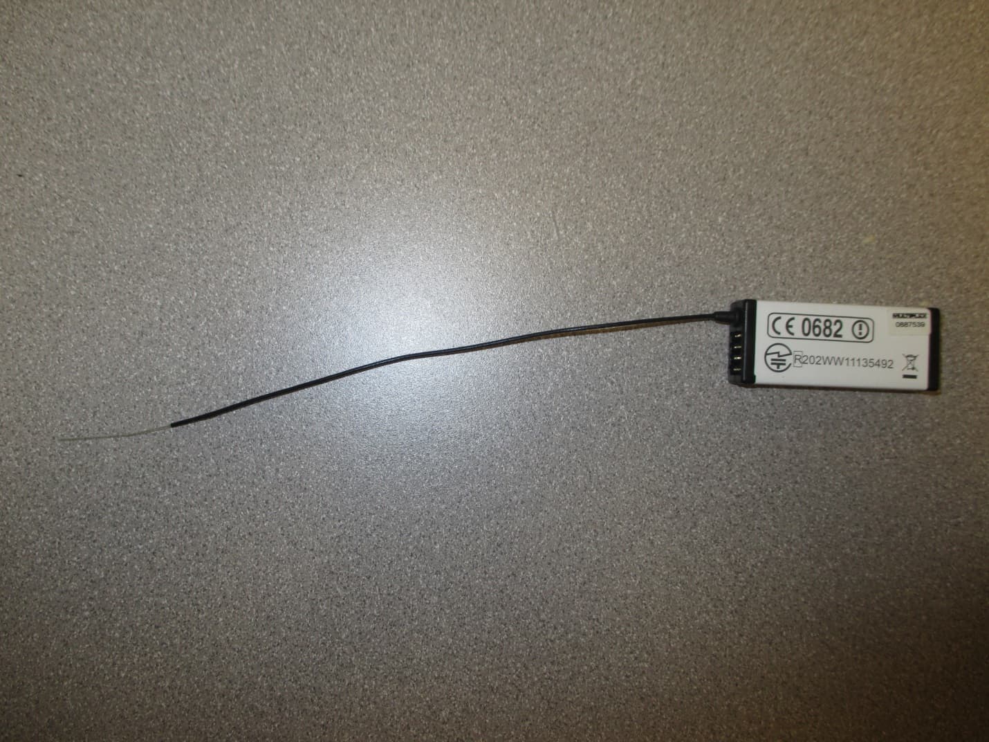
IFHRX57MLINK
Dec 22, 20147 CHANNEL 2.4 GHz TRANSCEIVER
Equipment Class
DSS - Part 15 Spread Spectrum Transmitter
IFHRX5MLINK
Dec 16, 2014RX5 M-LINK CHANNEL 2.4 GHz TRANSCEIVER
Equipment Class
DXX - Part 15 Low Power Communication Device Transmitter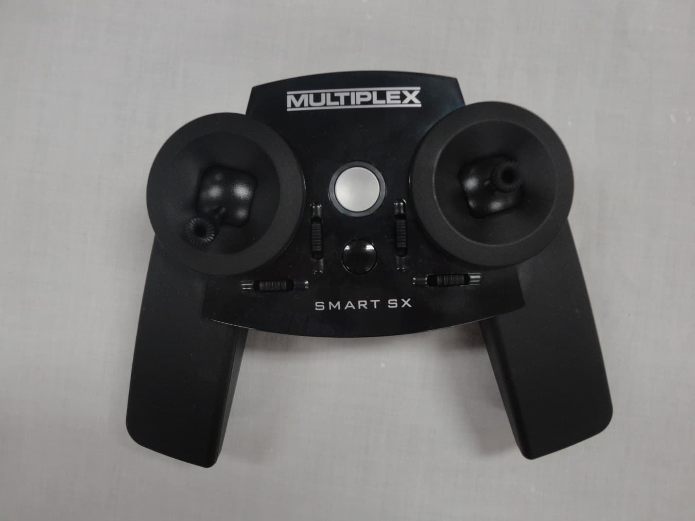
IFHSMART-SX
Sep 16, 20146 CHANNEL 2.4 GHz RADIO CONTROL TRANSMITTER
Equipment Class
DSS - Part 15 Spread Spectrum Transmitter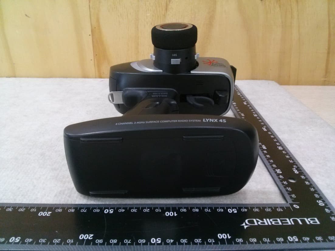
IFHLYNX4S
Jul 22, 20142.4GHz Radio Control System
Equipment Class
DSS - Part 15 Spread Spectrum Transmitter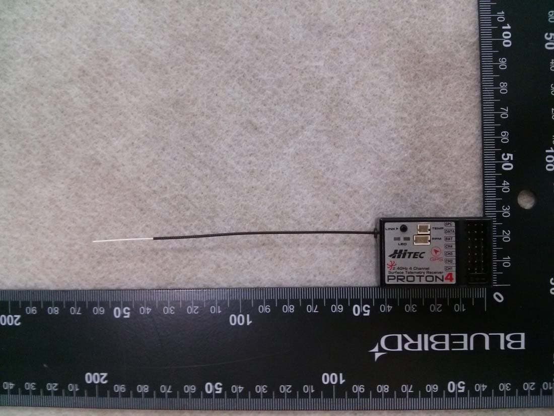
IFHPROTON4
Jul 22, 20142.4GHz Radio Control System
Equipment Class
DSS - Part 15 Spread Spectrum Transmitter