IFHOPTIC6SP72REMOTE CONTROL TRANSMITTER
Hitec RCD Inc.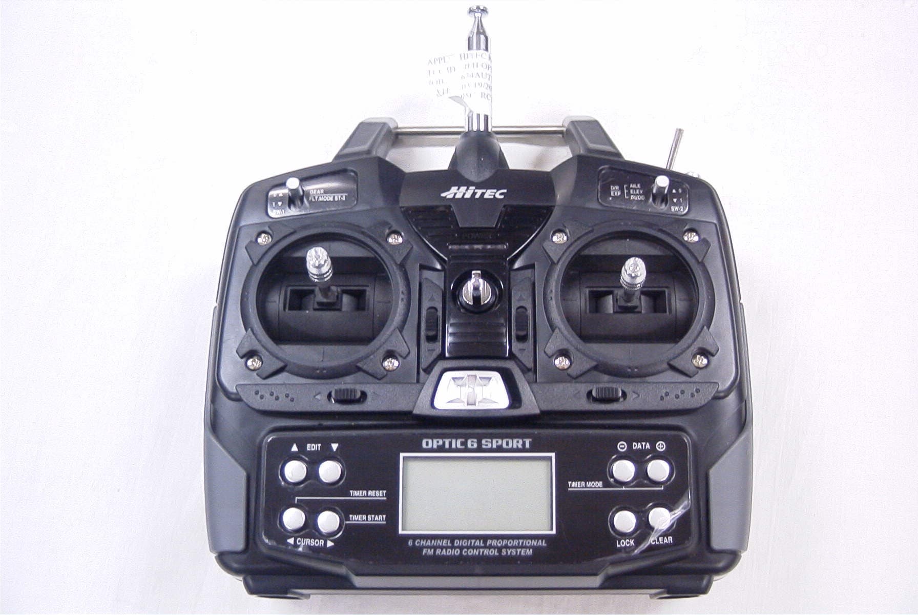
Click to zoom
Application Details
- Equipment Class
- TNB - Licensed Non-Broadcast Station Transmitter
- Date of Grant
- Apr 26, 2007
- Application Purpose
- Original Equipment
- Date of Application
- Apr 26, 2007
- Equipment Note
- REMOTE CONTROL TRANSMITTER
- Frequency Range
- 72.01000000 - 72.99000000
- Company
- Hitec RCD Inc.
- Country
- United States
Documents & Files
Document Text
Text extracted from the exhibit documents filed with the FCC. Open a document above to read the original.
Users Manual
Table of Contents - Page 2Table of Contents - Page 3 The Optic Sport's advanced features include: Model Memory: The computer's memory is capable of storing all the necessary trim settings and all the mixes and their nuances for each model (up to a total of ten models in the Optic Sport). The memory is non-volatile-that is, it won't be lost even if the transmitters battery is discharged or even removed. Shift Selectable: The signal output is shift-selectable: Within the initial setup menu you can tell the transmitter to output its signal in either positive or negative shift. This means any FM receiver, no matter what the brand, will work with this transmitter. Pre-mixed Flight Control Functions: The Optic Sport's computer automatically mixes rudder and elevator outputs to control a V-tail or mixes aileron and elevator outputs to create elevons for tail-less flying wings, eliminating the need for on-board mixing systems. Other pre-mixes include an aileron-to-rudder mix so turns are automatically coordinated and an elevator-to-flap mix for snap-turns. Sub-Trim Function: This computerized radio allows you to easily fine-tune and coordinate the control surfaces (such as keeping a rudder centered or two ailerons-each on their own servo-moving the same amount) without having to physically re-adjust linkages. Buddy-Box Function: For those learning to fly, the transmitter has a "buddy-box" capability so that you can use the optional trainer cord (part # xxxx) to connect your Optic Sport to a second Hitec transmitter. This allows one transmitter to be used by an instructor as the primary flight control while the other is controlled by the student pilot. Releasing a button instantly diverts control from the student's "slave" back to the master transmitter. Open Mix Capability: The Optic Sport also features one "open-mix" in which you can choose any two channels to mix the servos master-to-slave, such as mixing the throttle with the elevator to counteract pitching or the throttle with the rudder to reduce yawing If this is your first programmable radio control transmitter, you're probably feeling a bit overwhelmed by all the buttons and switches on the case and the cryptic symbols that appear on the radio's LCD screen. However, if you take the time to read this manual and follow the programming steps as you watch your model's control surfaces respond, programming the Optic Sport will soon become quite routine. So stick with it-learning the programming basics won't take any longer or require any more brain power than it takes to do the average crossword or Sudoku puzzle. You'll discover that the rewards for mastering this simple but powerful computerized, programmable radio are well worth the effort. *The Tip Sheet* Throughout the manual you will see our "Tip Sheet" notes. These highlight specific function details we didn't want you to miss within the body of the manual. Check these out, they can make programming the Optic Sport easier. Congratulations! You now own a basic, but unusually versatile and powerful, 6-Channel programmable RC transmitter. The Optic Sport is all the radio you need to fly most types of fixed-winged aircraft-from standard trainers to flying wings to 3-D aerobatic models to sailplanes (both powered or pure)-as well as most classes of helicopters. As you will learn later in this manual, the ability of this radio to mix and control many of the channel outputs in a variety of ways allows you to create some surprisingly sophisticated flying functions that were once available only in much more complex and expensive radios. Standard programming features include servo-reversing for all channels, subtrim adjustments on all channels, end point adjustment on all channels and selectable dual rate and exponential values for the ailerons, elevator and rudder. The primary limitation of this radio is that your models require six or less control channels. Introducing the Optic Sport If you are new to Computerized RC Transmitters: Introducing the Optic Sport Table of Contents - Page 4Table of Contents - Page 5 Be careful if you do choose to use a field charger on your batteries. A fast-charger may overcharge the batteries, causing overheating and a premature failure. Never charge your transmitter or receiver battery at a rate higher than the batteries capacity. For example, the capacity of your Optic 6 Sport's 7.2 volt NIMH battery is 1300 mAh and should therefore not be charged at a rate any higher than 1.3 amps. Be sure to recharge the batteries before each flying session. A battery low in charge will soon die, causing loss of control and a crash. Plug in the charger that comes in this system and hook up the transmitter and airborne batteries the day before a planned flying session. Be sure the charger is not turned off by the room's light on-off switch! Important!: Quit flying when your transmitter battery level reaches 6.6 volts-the radio will emit a steady series of beeps to remind you! Mode 1 Configuration All Optic Sport systems sold in America are in the Mode 2 format. While most pilots in America fly with their transmitter in the "mode 2" configuration, you may wish to use your new Optic sport in the "mode 1" format. There is a choice for this option in the Model Set-Up function menu described on Page XX. After selecting Mode 1 in the Model Set-Up menu, You must do the following to change the Optic Sport transmitter to Mode 1. We must add this info later. Once you arrive at the flying field... Before flying, be sure that the frequency you intend to fly with is not in use, and secure any frequency control device (pin, tag, etc.) for that frequency before turning on your transmitter. Never believe that it's possible to fly two or more models on the same frequency at the same time. Even though there are different types of modulation (AM, PPM or FM, and PCM), only one model may be flown on a single frequency. When you are ready to fly your model, position the throttle stick or switch to i…
Text truncated - open the document above for the full version.
Cover Letter(s)
12115 Paine Street, Poway CA 92064 TEL(858)748-6948 FAX(858)748-1767 WWW.HITECRCD.COM 03/07/2007 Federal Communications Commission Authorization and Evaluation Division Confidentiality Request regarding application for certification of FCC ID:IFHOPTIC6SP72 Pursuant to Sections 0.457 and 0.459 of the Commission’s Rules, we hereby request confidential treatment of information accompanying this application as outlined below: Schematics Board Layout Description of Operation Parts List Tuning Procedure The above materials contain trade secrets and proprietary information not customarily released to the public. The public disclosure of these materials may be harmful to the applicant and provide unjustified benefits to its competitors. The applicant understands that pursuant to Section 0.457 of the Rules, disclosure of this application and all accompanying documentation will not be made before the date of the Grant for this application. Sincerely, Tony Ohm HITEC RCD USA, LLC
ID Label/Location Info
FCC ID: IFHOPTIC6SP72 Optic Sport Made in the Philippines
Test Report
TIMCO ENGINEERING INC. 849 NW State Road 45 Newberry, Florida 32669 http://www.timcoengr.com 888.472.2424 F 352.472.2030 email: [email protected] APPLICANT: HITEC RCD INC. FCC ID: IFHOPTIC6SP72 REPORT #: H\HITEC_IFH\634AUT7\634AUT7TestReport.doc COVER SHEET Test Report Product Name: 6 CHANNEL PROPORTIONAL FM RADIO CONTROL SYSTEM FCC ID: IFHOPTIC6SP72 Applicant: HITEC RCD INC. 12115 PAINE STREET POWAY CA 92064 USA Date Receipt: 3/19/2007 Date Tested: 3/19/2007 TIMCO ENGINEERING INC. 849 NW State Road 45 Newberry, Florida 32669 http://www.timcoengr.com 888.472.2424 F 352.472.2030 email: [email protected] APPLICANT: HITEC RCD INC. FCC ID: IFHOPTIC6SP72 REPORT #: H\HITEC_IFH\634AUT7\634AUT7TestReport.doc TABLE OF CONTENTS TABLE OF CONTENTS LIST TEST REPORT: PAGE 1............GENERAL INFORMATION & TECHNICAL DESCRIPTION PAGE 2............TECHNICAL DESCRIPTION CONTINUED RF POWER OUTPUT PAGE 3............MODULATION CHARACTERISTICS AUDIO FREQUENCY RESPONSE OCCUPIED BANDWIDTH PAGE 4............OCCUPIED BANDWIDTH PLOT PAGE 5............FIELD STRENGTH OF SPURIOUS EMISSION PAGE 6............METHOD OF MEASURING RADIATED SPURIOUS EMISSIONS PAGE 7............FREQUENCY STABILITY PAGE 8............TEST EQUIPMENT LIST EXHIBITS INCLUDING: BLOCK DIAGRAM SCHEMATIC PARTS LIST USERS MANUAL LABEL SAMPLE LABEL LOCATION EXTERNAL PHOTOGRAPHS INTERNAL PHOTOGRAPHS ALIGNMENT PROCEDURE OPERATIONAL DESCRIPTION TEST SET UP PHOTOGRAPH TIMCO ENGINEERING INC. 849 NW State Road 45 Newberry, Florida 32669 http://www.timcoengr.com 888.472.2424 F 352.472.2030 email: [email protected] APPLICANT: HITEC RCD INC. FCC ID: IFHOPTIC6SP72 REPORT #: H\HITEC_IFH\634AUT7\634AUT7TestReport.doc Page 1 of 10 GENERAL INFORMATION 2.1033(c)(1)(2) HITEC RCD INC. will sell the FCC ID:IFHOPTIC6SP72 Radio Control transmitter in quantity, for use under PART 95 SUBPART C. HITEC RCD INC. 12115 PAINE STREET POWAY CA 92064 2.1033(c)(3) Instruction manual is included in the exhibits. 2.1033 (4) Type of Emission: 8K0F1D 95.631 (b)(5) Bn = 2M + 2DK M = 4,800 Bits per second D = 800 Hz (Peak Deviation) K = 1 Bn = 2(4.8/2) + 2(1600)(1) =4.8K + 3.2K =8.0k ALLOWED AUTHORIZED BANDWIDTH = 8.00 kHz. 95.631 (b) Authorized Bandwidth 8 kHz for RC Transmitter 2.1033(c)(6) Frequency Range: 72.01 - 72.99 MHz 95.623 (a)(7) Power Range and Controls: There are no user power controls. (8) Function of each electron tube or semiconductor device or other active circuit device are included in the exhibits (9) Maximum Output Power Rating: 0.3 W ERP. (10) DC Voltages and Current into Final Amplifier: FINAL AMPLIFIER ONLY Vce = 7.2 VDC Ice = 0.07 A. Pin = 0.5 W 2.1033(c)(11) Tune-up procedure. The tune-up procedure is included in the exhibits. TIMCO ENGINEERING INC. 849 NW State Road 45 Newberry, Florida 32669 http://www.timcoengr.com 888.472.2424 F 352.472.2030 email: [email protected] APPLICANT: HITEC RCD INC. FCC ID: IFHOPTIC6SP72 REPORT #: H\HITEC_IFH\634AUT7\634AUT7TestReport.doc Page 2 of 10 2.1033(c)(12) Complete Circuit Diagrams: The circuit diagrams are included in the exhibits. (13) Description of all circuitry and devices provided for determining and stabilizing frequency is given in the exhibits. 2.1033(c)(14) The equipment identification is shown in the exhibits. 2.1033(c)(15) Photographs of the equipment are shown in the exhibits. 2.1033(c)(16) Equipment employing digital modulation. N/A. 2.1033(c)(17) The data required by 2.1046-2.1057 follows; 2.1046 RF power is measured by the ERP method. There are no provisions to limit the power. With a nominal battery voltage of 7.2 VDC, and the transmitter properly adjusted the RF output measures: Po = .20 Watts ERP 2.1046 RF power output. SIGNAL GENERATOR DIPOLE ANTENNA TRANSMITTER UNDER TEST WITH INTERNAL ANTENNA 3.0 METERS TUNED, CALIBRATED ANTENNA, WHICH MAY BE RAISED FROM 1 TO 4 METERS ABOVE GROUND AND CHANGED IN POLARIZATION HP SPECTRUM ANALYZER Equipment placed 80 cm. above ground on a rotatable platform. TIMCO ENGINEERING INC. 849 NW State Road 45 Newberry, Florida 32669 http://www.timcoengr.com 888.472.2424 F 352.472.2030 email: [email protected] APPLICANT: HITEC RCD INC. FCC ID: IFHOPTIC6SP72 REPORT #: H\HITEC_IFH\634AUT7\634AUT7TestReport.doc Page 3 of 10 2.1047 Modulation characteristics: AUDIO FREQUENCY RESPONSE The Voice is NOT allowed in this band. 2.1049 Occupied bandwidth: 95.635 (b) (1) At least 25dB on any frequency removed from the center of the authorized bandwidth by more than 50% up to and including 100% of the authorized bandwidth. (2) At least 45 dB on any frequency removed from the center of the authorized bandwidth by more than 100% up to and including 125% of the authorized bandwidth. (3) At least 55 dB on any frequency removed from the center of the authorized bandwidth by more than 125% up to and including 250% of the authorized bandwidth. (4) At least 56 + 10 log 10 (T) dB on any frequency removed from the center of the authorized bandwidth by more than 250%. Radiotelephone Transmitter with Modulation Limiter Test Procedure Diagram OCCUPIED BANDWIDTH MEASUREMENT TRANSMITTER UNDER TEST AUDIO OSCILLATOR 50 ohm RESISTIVE WATTMETER TIMCO ENGINEERING INC. 849 NW State Road 45 Newberry, Florida 32669 http://www.timcoengr.com 888.472.2424 F 352.472.2030 email: [email protected] APPLICANT: HITEC RCD INC. FCC ID: IFHOPTIC6SP72 REPORT #: H\HITEC_IFH\634AUT7\634AUT7TestReport.doc Page 4 of 10 OCCUPIED BANDWIDTH PLOT TIMCO ENGINEERING INC. 849 NW State Road 45 Newberry, Florida 32669 http://www.timcoengr.com 888.472.2424 F 352.472.2030 email: [email protected] APPLICANT: HITEC RCD INC. FCC ID: IFHOPTIC6SP72 REPORT #: H\HITEC_IFH\634AUT7\634AUT7TestReport.doc Page 5 of 10 2.1051 SPURIOUS EMISSIONS AT ANTENNA TERMINALS NOT APPLICABLE, No antenna port. This UUT has a permanently attached antenna. 2.1053 UNWANTED RADIATION: 95.635(1)(3)(7)(10)(11)(12) REQUIREMENTS: At least 56 + 10log(T) on any frequency removed from the center of the authorized bandwidth by more than 250%. 56 + 10log(0.2) = 49 dB TEST DATA: Em…
Text truncated - open the document above for the full version.
Contact Information
Applicant
Tony Ohm(Service Dept. Manager)
Test Firm
Timco Engineering, Inc.Sid Sanders
Technical Specifications
| # | Rule Parts | Frequency Range | Power Output | Emission | Tolerance |
|---|---|---|---|---|---|
| 1 | 95C | 72.01 MHz - 72.99 MHz | 200.00 mW | 8K0F1D | 20.0000000000 ppm |
Other Applications from Hitec RCD Inc.
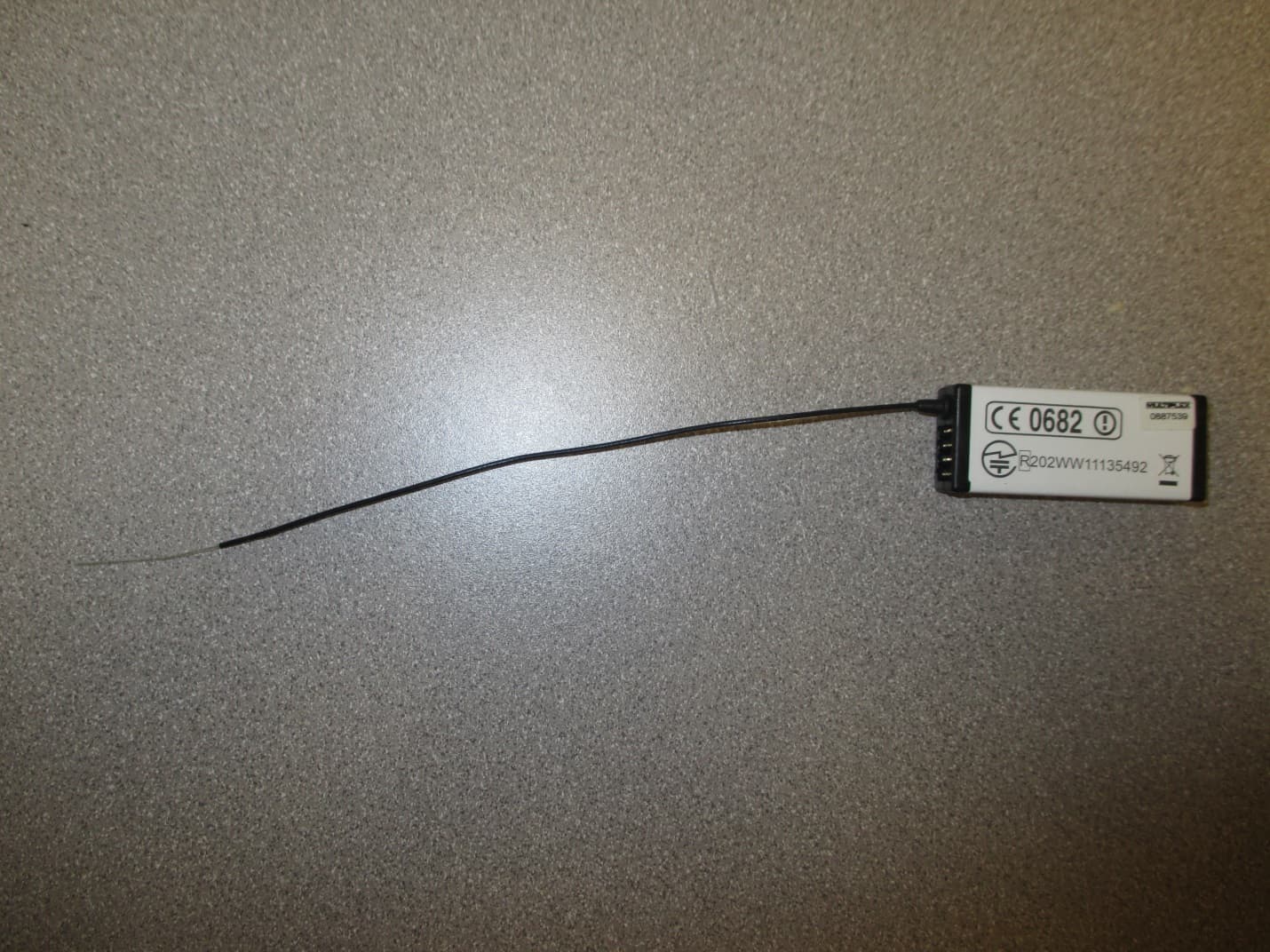
IFHRX57MLINK
Dec 22, 20147 CHANNEL 2.4 GHz TRANSCEIVER
Equipment Class
DSS - Part 15 Spread Spectrum Transmitter
IFHRX5MLINK
Dec 16, 2014RX5 M-LINK CHANNEL 2.4 GHz TRANSCEIVER
Equipment Class
DXX - Part 15 Low Power Communication Device Transmitter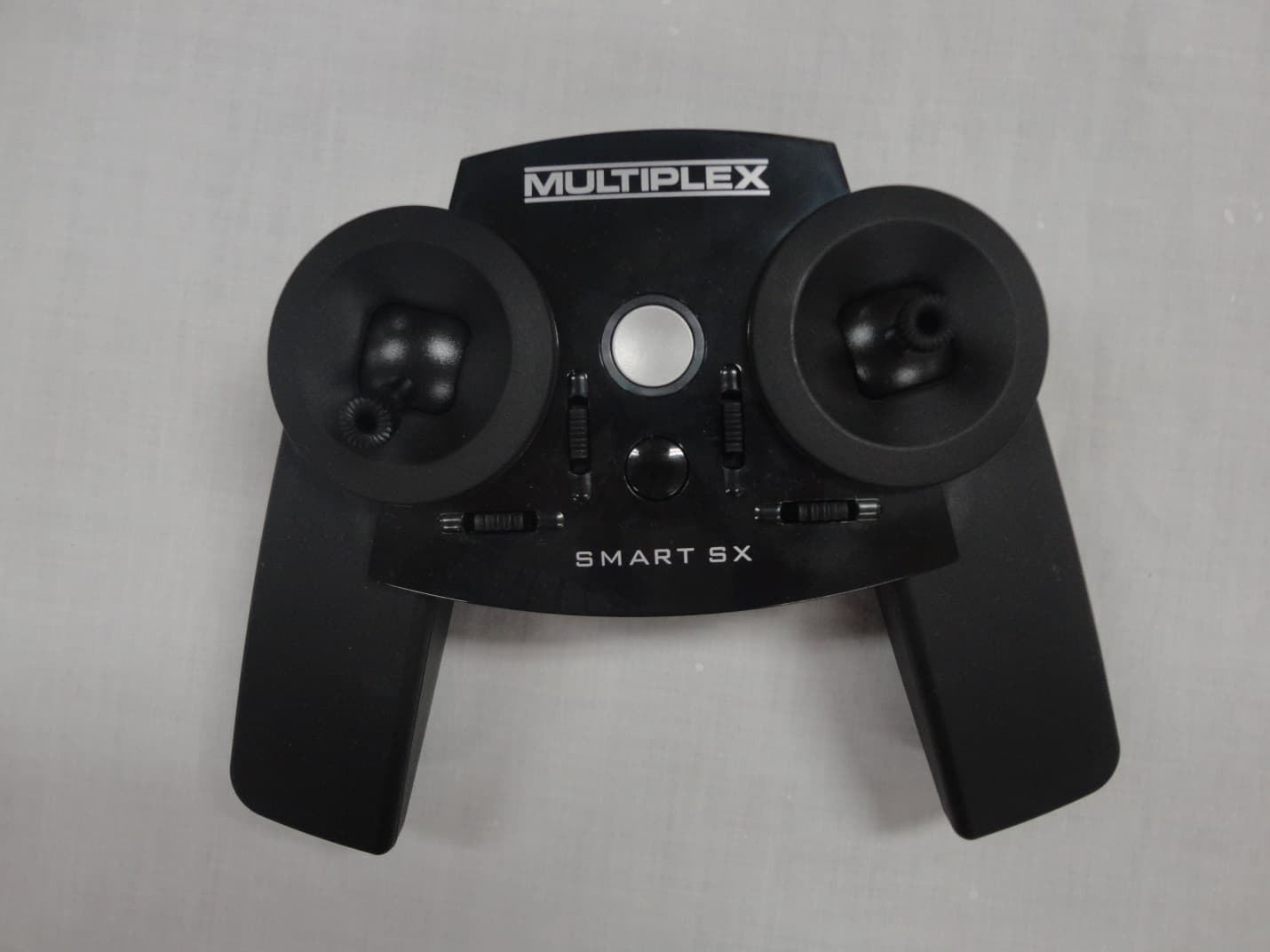
IFHSMART-SX
Sep 16, 20146 CHANNEL 2.4 GHz RADIO CONTROL TRANSMITTER
Equipment Class
DSS - Part 15 Spread Spectrum Transmitter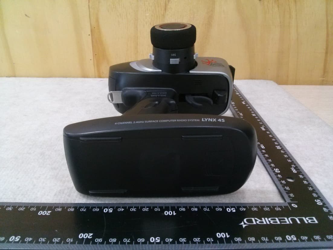
IFHLYNX4S
Jul 22, 20142.4GHz Radio Control System
Equipment Class
DSS - Part 15 Spread Spectrum Transmitter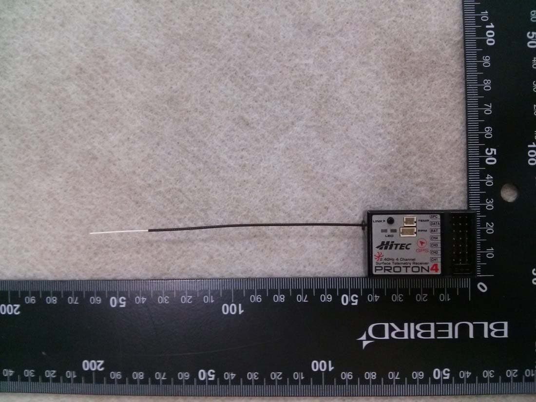
IFHPROTON4
Jul 22, 20142.4GHz Radio Control System
Equipment Class
DSS - Part 15 Spread Spectrum Transmitter