IFHR3F75BRemote Control Transmitter
Hitec RCD Inc.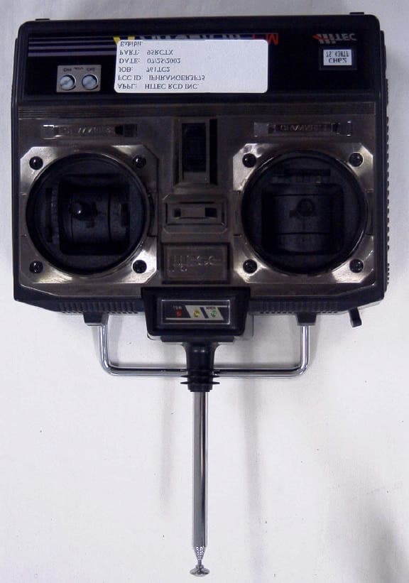
Click to zoom
Application Details
- Equipment Class
- TNB - Licensed Non-Broadcast Station Transmitter
- Date of Grant
- Sep 23, 2002
- Application Purpose
- Original Equipment
- Date of Application
- Sep 23, 2002
- Equipment Note
- Remote Control Transmitter
- Frequency Range
- 75.41000000 - 75.99000000
- Company
- Hitec RCD Inc.
- Country
- United States
Documents & Files
Document Text
Text extracted from the exhibit documents filed with the FCC. Open a document above to read the original.
Users Manual
3 CHANNEL NON BEC WELCOME TO THE INTRIGUING WORLD OF R/C Thank you for purchasing the Ranger 3 channel FM radio system and thereby entering into the wonderful world of radio control model hobby. The Ranger 3 radio is the finest of its kind using the latest electronic technologies thereby assuring the best performance and highest quality. Team up with Hitec, “The R/cer’s Partner” and you will enjoy the many facets of R/C fun. (WARNING) Please note that the receiver of RANGER 3 FM is not equipped with a Battery Eliminator Circuit. So don’t exceed 6 volts Only use 4 cell “AA” size batteries, 4-5 cell NiCad batteries or an electronic speed controller which has a B.E.C.. FEATURES AND SPECIFICATIONS A.TRANSMITTER • 3 CHANNEL FM TRANSMITTER FOR REAL TIME SERVO RESPONSE • CRYSTAL INTERCHANGEABLE • TWO CHANNEL SERVO REVERSING SWITCHES • CHARGER CONNECTOR FOR NICAD BATTERIES (8 CELL 9.6V) • ADJUSTABLE SERVO TRAVELING (ATV) FOR STEERING AND THROTTLE • QUICK START/BRAKE FUNCTION FOR FAST RESPONSE OF THROTTLE • ALL SMT CIRCUITRY B.RECEIVER (NON B.E.C.) • FM SINGLE CONVERSION RECEIVER FOR NOISE PROOF • CRYSTAL INTERCHANGEABLE • SIZE AND WEIGHT • SIZE: 48 X 29 19mm (1.9 X 1.1 X 0.7”), WEIGHT 22.5g (0.79oz) C.SERVO • HEAVY DUTY AND DUST RESISTANT DESIGN • HIGH SPEED: 0.16sec / 60º • HIGH TORQUE: 3.5kg/CM (44oz/in) • HITEC CUSTOM CHIP FOR NARROW DEADBAND • ALL SMT CIRCUITRY CH 3 VARIABLE SWITCH NEUTRAL POSITION LEVER THROTTLE CONTROL STICK THROTTLE TRIM LEVER CONNECTOR JACK CARRYING HANDLE POWER METER STEERING CONTROL STICK STEERING TRIM LEVER TRANSMITTER POWER SWITCH TRANSMITTER CRYSTAL STEERING SERVO REVERSE SWITCH THROTTLE SERVO REVERSE SWITCH TRANSMITTER ANTENNA RANGER 3 CH FM LAYOUT DIAGRAM BATTERY HARNESS (1.5v X 4) RECEIVER SWITCH RECEIVER CRYSTAL RECEIVER ANTENNA (CH 3) (CH 2) (CH 1) THE VARIOUS USES OF THREE CHANNEL RADIOS A.VEHICLES & BOATS You can operate all model vehicles and boats of course with this advanced three-channel radio whether they are engine powered of battery operated. Since the basic maneuver of all vehicles and boats is throttle and steering (rudder), two-channel operation is all you need in most cases. However the third channel provides one more auxiliary channel you can use for whatever purpose you may desire. B.AIRPLANES & GLIDERS The main use of the third channel for aircrafts would be throttle control. The third channel of this radio is designed exactly for this purpose. After lifting the aircraft in the air, you will be able to control speed and or turn off the power to let it soar by controlling the variable switch of the third channel. To control speed or turn off the power in the air, you may need another accessory item such as the Hitec SP-1801N Speed control or the SP-1003 ON/OFF control. The Sp-1801N will provide proportional speed control from neutral to high end and the SP-*1003 will do ON/OFF control without any extra servo for throttle. Also, both of the have Battery Eliminator Circuits and Auto Cut OFF function so there is nothing else needed for enjoying the 3-channel aircraft model. C.OTHERS You may find many other models too numerous to mention or categorize such as tanks, submarines, parachute planes, rocket launched gliders hovercraft etc... (WARNING) Please note that certain frequencies are to be used solely for airborne uses as well as certain frequencies earmarked only for surface use, so please consult your local club or hobby store to make sure. (EXAMPLE) In the U.S.A. 75MHZ: For surface only, 72MHz: For Aircraft only SETTING UP Please read the following section carefully before installation and operation of your new model. The instruction was written with the beginner in mind but even experienced modelers should take note. A.BATTERY INSTALLATION The transmitter uses eight “AA” size batteries and four for the receiver. We recommend using the NiCad batteries whenever possible as it will prove to be far more economical in the long run. 1) When loading the batteries, please make sure the transmitter and the receiver switches are in the off positions. 3 CHANNEL WORLD VEHICLESAIRCRAFT ON-ROAD CAR OFF-ROAD BUGGY MONSTER TRUCKS OTHERSBOATSSHIPSOTHERSGLIDERSAIRPLANESOTHERS 2) Open the battery compartment at the back of the transmitter by pressing the cover down and toward the bottom. (See fig 2) 3) Load batteries into the slots paying close attention to the polarity. (See fig 2) 4) Replace the battery cover and turn the power “ON” to see if the indicating arrow will move up. If the batteries are fresh, the indicating arrow will move to the far right side but if the arrow is in the low power or lower part of the yellow zone, you had better replace the batteries or recharge your NiCad batteries. (See fig 3) Loading Battery fig 2 Power indicating fig 3 BATTERY COVER PRESS DOWN AND TOWARD BOTTOM 8 AA SIZE BATTERY BE CAREFUL TO LOAD BATTERIES IN THE RIGHT DIRECTION Full power: White zone Medium power: Yellow zone Low power: Red zone B. OPERATION CHECK 1) Gently plug the switch harness and servo connectors into the proper slots of the receiver. The connectors are polarized, thus, should fit only one-way. If they will not go in one-way, reverse it and see if it will plug in. Never use excessive force to plug in connectors. (See fig 1). 2) Turn the transmitter power switch “ON” first, then the receiver switch. Always remember to turn the transmitter on the transmitter before you turn the receiver on, otherwise your receiver may receive other interfering signals from other radio sources and jitter. 3) Check to see if the servos move when you control the sticks. Move the trim lever to the center position. (See fig 4) 4) Check the direction of the servo rotation. If you wish to change the direction of the servo, push the servo reversing switch and check if it changes direction as you desired. (See fig 4) 5) If you wish to have more forward throttle than backward, you can push down the neutral position adjustment lever. You will have 30% more forward than backward. The …
Text truncated - open the document above for the full version.
ID Label/Location Info
FCC ID: IFHR3F75B Model Ranger 3FM
Operational Description
Ranger 3 Fm FCC ID#: IFHR3F75B Operational Description The Ranger 3 FM is a low power, non-voice, transmitter intended for remote control of model vehicles in the 75MHz band. The unit is held with two hands in front of the body. The equipment employs a vertical polarized antenna, directly mounted on the unit and meets Paragraphs 95.645, 95.647, 95.649, and the technical requirements established in the Report & Order in PR Docket 90-222. Circuits and Devices to Stabilize Frequency Transmitter output frequency is determined and stabilized by crystal-controlled oscillator. Circuits to suppress Spurious Radiation Final RF amplifier spurious emissions are attenuated by a “PI” matching network consisting of C43, L2, C28, C32, C29, L3, T4, and T5. Functions of Active Semiconductors Reference Type Function Q1 C1623 Buffer/SW Q3 C1623 Modulator Q4 C2223 Driver/ X-Tal Oscillator Q5 C2223 Driver Q6 C4735 Final amplifier IC2 KS86P4004 Encoder
Test Report
APPLICANT: HITEC RCD INC. FCC ID: IFHR3F75B REPORT #: T:\H\HITEC\761TC2\761TC2TestReport.doc TABLE OF CONTENTS LIST TABLE OF CONTENTS LIST APPLICANT: HITEC RCD INC. FCC ID: IFHR3F75B TEST REPORT: PAGE 1......COVER SHEET - GENERAL INFORMATION & TECHNICAL DESCR. PAGE 2......TECHNICAL DESCRIP. CONTD. & RF POWER OUTPUT PAGE 3......MOD CHARACTERISTICS AND OCCUPIED BANDWIDTH PAGE 4......OCCUPIED BANDWIDTH PLOT PAGE 5......FIELD STRENGTH OF SPURIOUS EMISSION AND UNWANTED RADIATION EMISSIONS PAGE 6......METHOD OF MEASURING RADIATED SPURIOUS EMISSIONS PAGE 7......FREQUENCY STABILITY PAGE 8-11...TEST EQUIPMENT LIST EXHIBIT CONTAINING: EXHIBIT 1..........FCC ID LABEL SAMPLE & LOCATION EXHIBIT 2..........EXTERNAL PHOTOS EXHIBIT 3..........INTERNAL PHOTOS EXHIBIT 4..........SCHEMATIC EXHIBIT 5..........USER'S MANUAL EXHIBIT 6..........CIRCUIT DESCRIPTION EXHIBIT 7..........TUNING PROCEDURE EXHIBIT 8..........TEST SET UP PHOTO APPLICANT: HITEC RCD INC. FCC ID: IFHR3F75B REPORT #: T:\H\HITEC\761TC2\761TC2TestReport.doc Page 1 of 11 GENERAL INFORMATION 2.1033(c)(1)(2) HITEC RCD INC.will sell the FCCID: IFHR3F75B Radio Control transmitter in quantity, for use under FCC RULES PART 95 SUBPART C. HITEC RCD INC. 1211 PAINE STREET POWAY, CA 92064 2.1033(c)(3) Instruction manual is included as exhibit #5. 2.1033 (4) Type of Emission: 9K2F1D 95.631(b)(1) Bn = 2M + 2DK M = 4,800 Bits per second D = 2.2KHz (Peak Deviation) K = 1 Bn = 2(4800/2) + 2(2.2K)(1) = 4.8K + 4.4K = 9.2k ALLOWED AUTHORIZED BANDWIDTH = 20.00KHz. 95.631(b) Authorized Bandwidth 20KHz for F1D 2.1033(c)(5) Frequency Range: 75.41 – 75.99 MHz 95.623(a) (6) Power Range and Controls: There are NO user Power controls. (6) Function of each electron tube or semiconductor device or other active circuit device: See Exhibit #6. (7) Maximum Output Power Rating: .1 Watts ERP. (8) DC Voltages and Current into Final Amplifier: FINAL AMPLIFIER ONLY Vce = 12.6Volts DC Ice = 0.039A. Pin = 0.5Watts 2.1033(c)(9) Tune-up procedure. The tune-up procedure is included as Exhibit #7. APPLICANT: HITEC RCD INC. FCC ID: IFHR3F75B REPORT #: T:\H\HITEC\761TC2\761TC2TestReport.doc Page 2 of 11 2.1033(c)(10) Complete Circuit Diagrams: The circuit diagram is included as part of Exhibit # 4. (10) Description of all circuitry and devices provided for determining and stabilizing frequency is given in PAGES 37-38 of this report. The crystal specifications are included as EXHIBT #6. 2.1033(c)(11) The Equipment identification is shown as Exhibit #1. 2.1033(c)(12) Photographs of the equipment are shown as Exhibits No. 2-3. 2.1033(c)(13) Equipment employing Digital modulation. N/A. 2.1033(c)(14) The data required by 2.1046-2.1057 follows; 2.1046 RF power is measured by the ERP METHOD. There is no provisions to limit the power. With a nominal battery voltage of 12.6 VDC, and the transmitter properly adjusted the RF output measures: Po = .1 Watts 2.1046 RF power output. APPLICANT: HITEC RCD INC. FCC ID: IFHR3F75B REPORT #: T:\H\HITEC\761TC2\761TC2TestReport.doc Page 3 of 11 2.1047 Modulation characteristics: AUDIO FREQUENCY RESPONSE The Voice is NOT allowed in this band. 2.1049 Occupied bandwidth: 95.635(b) At least 25dB on any frequency removed from the center of the authorized bandwidth by more that 50% up to and including 100% of the authorized bandwidth. At least 35dB on any frequency removed from the center of the authorized bandwidth by more that 100% up to and in- cluding 250% of the authorized bandwidth. At least 43+log10(T) on any frequency removed from the center of the authorized bandwidth by more that 250%. At least 45dB on any frequency removed from the center of the aurhorized bandwidth by more that 100% up to and in- cluding 125% of the authorized bandwidth. At least 55dB on any frequency removed from the center of the authoriz- ized bandwidth by more that 125% up to and including 250% of the authorized bandwidth. At least 56+log10(T) on any frequency removed from the center of the authorized bandwidth by more that 250%. Radiotelephone transmitter with modulation limiter. Test procedure diagram OCCUPIED BANDWIDTH MEASUREMENT APPLICANT: HITEC RCD INC. FCC ID: IFHR3F75B REPORT #: T:\H\HITEC\761TC2\761TC2TestReport.doc Page 4 of 11 OCCUPIED BANDWIDTH PLOT APPLICANT: HITEC RCD INC. FCC ID: IFHR3F75B REPORT #: T:\H\HITEC\761TC2\761TC2TestReport.doc Page 5 of 11 2.1051 SPURIOUS EMISSIONS AT ANTENNA TERMINALS. NOT APPLICABLE, NO antenna port. This UUT has a permanently attached antenna. 2.1053 UNWANTED RADIATION: 95.635(1)(3)(7)(10)(11)(12) REQUIREMENTS: At least 56 + 10log(T) on any frequency removed from the center of the authorized bandwidth by more than 250%. 56 + 10log(0.1) = 46.00dB TEST DATA: Tuned Frequency MHz Emission Frequency MHz ATTN dB dBm 75.5 75.50 00.0 10.39 75.5 150.90 77.11 -67 75.5 150.90 64.51 -54 75.5 226.40 79.85 -70 75.5 226.40 74.25 -64 75.5 301.90 89.53 -79 75.5 301.90 79.73 -69 75.5 377.40 91.68 -81 METHOD OF MEASUREMENT: The procedure used was C63.4-1992 with the unit. The unit was operating into its permanently attached antenna at a height of four feet. The spectrum was scanned from 30 to at least the tenth haromonic of the fundamental using a HP model 8566B spectrum analyzer, an Eaton model 94455-1 Biconical Antenna, ElectroMetrics antennas models TDA, TDS-25-1, TDS-25-2 & RGA 180. Measurements were made at the open field test site of TIMCO ENGINEERING INC. located at 849 N.W. State Road 45 Newberry, FL 32669. APPLICANT: HITEC RCD INC. FCC ID: IFHR3F75B REPORT #: T:\H\HITEC\761TC2\761TC2TestReport.doc Page 6 of 11 Method of Measuring Radiated Spurious Emissions APPLICANT: HITEC RCD INC. FCC ID: IFHR3F75B REPORT #: T:\H\HITEC\761TC2\761TC2TestReport.doc Page 7 of 11 2.1055(a)(1) Frequency stability: 95.623(b) Temperature and voltage tests were performed to verify that the frequency remains within the .002%, 20 ppm specification limit. The test was conducted as follows: The transmitter was placed in the temperature chamber at 25 degrees C and allowed …
Text truncated - open the document above for the full version.
Contact Information
Applicant
Tony Ohm(Service Dept. Manager)
Test Firm
Timco Engineering, Inc.S Sanders
Technical Specifications
| # | Rule Parts | Frequency Range | Power Output | Emission | Tolerance |
|---|---|---|---|---|---|
| 1 | 95C | 75.41 MHz - 75.99 MHz | 100.00 mW | 9K20F1D | 20.0000000000 ppm |
Other Applications from Hitec RCD Inc.
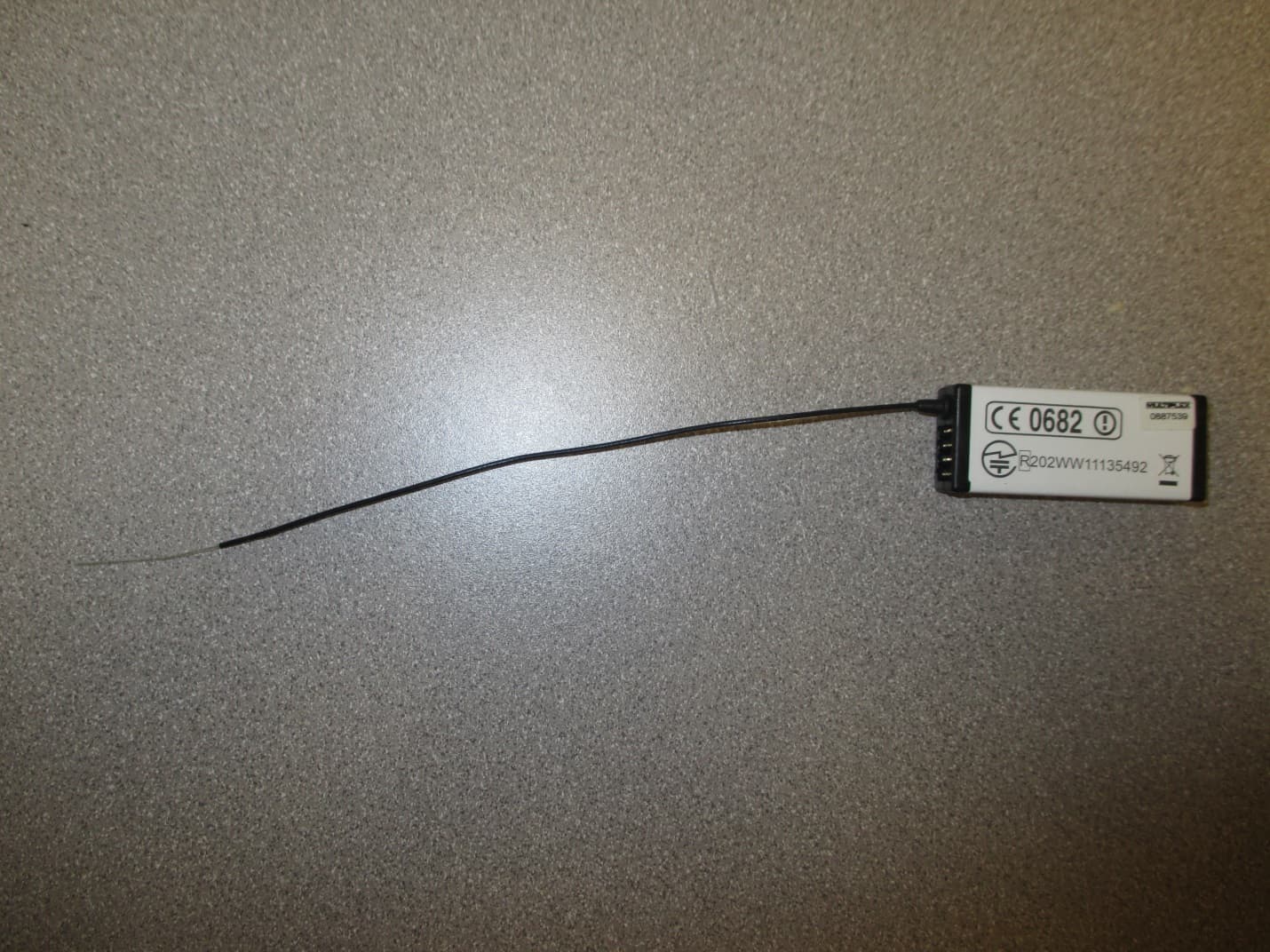
IFHRX57MLINK
Dec 22, 20147 CHANNEL 2.4 GHz TRANSCEIVER
Equipment Class
DSS - Part 15 Spread Spectrum Transmitter
IFHRX5MLINK
Dec 16, 2014RX5 M-LINK CHANNEL 2.4 GHz TRANSCEIVER
Equipment Class
DXX - Part 15 Low Power Communication Device Transmitter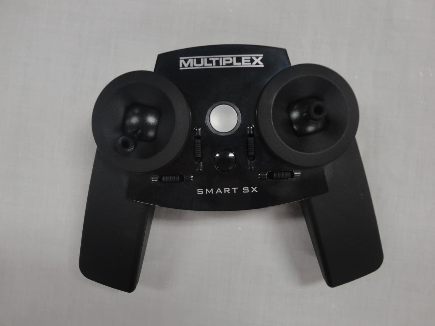
IFHSMART-SX
Sep 16, 20146 CHANNEL 2.4 GHz RADIO CONTROL TRANSMITTER
Equipment Class
DSS - Part 15 Spread Spectrum Transmitter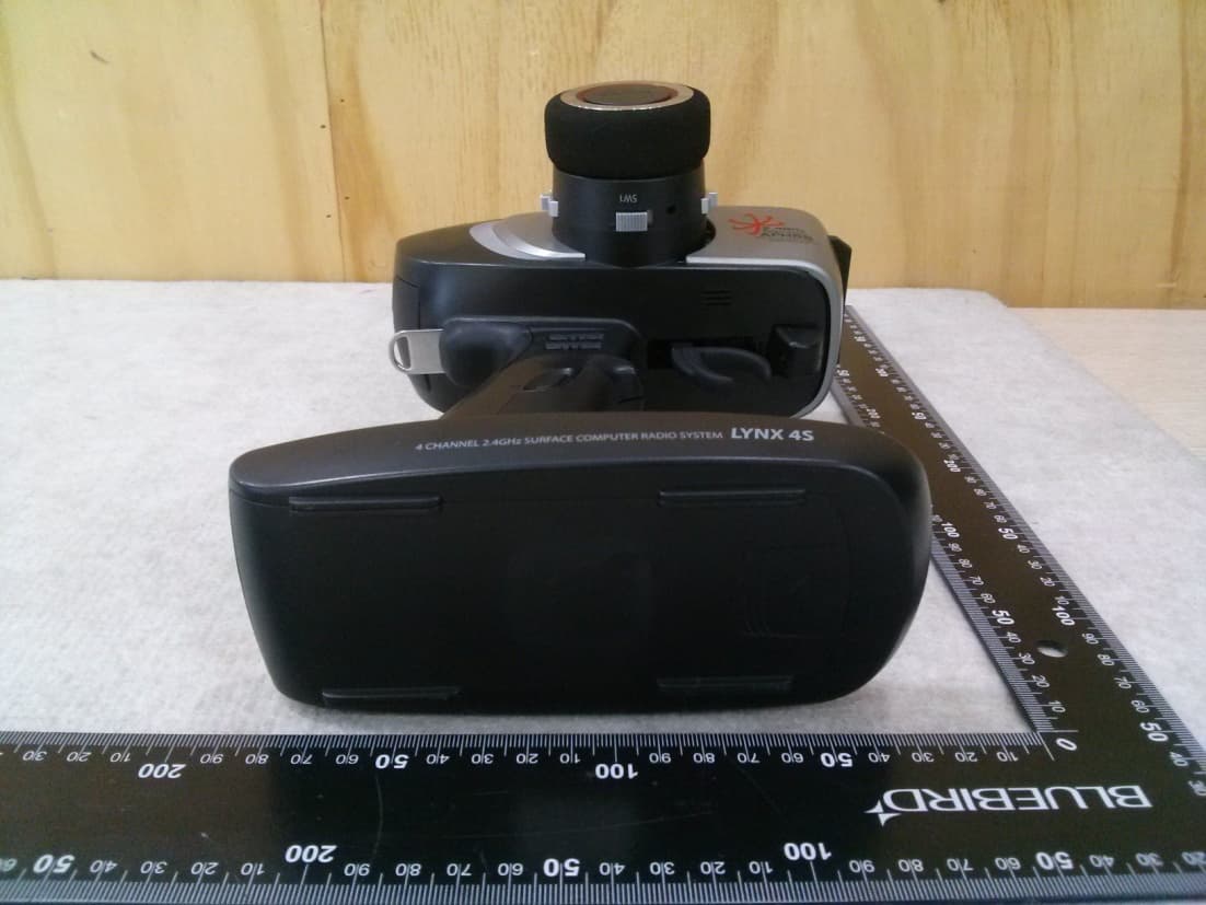
IFHLYNX4S
Jul 22, 20142.4GHz Radio Control System
Equipment Class
DSS - Part 15 Spread Spectrum Transmitter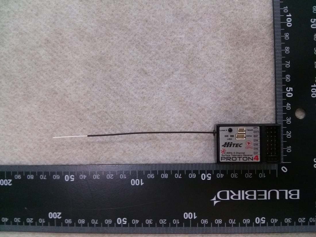
IFHPROTON4
Jul 22, 20142.4GHz Radio Control System
Equipment Class
DSS - Part 15 Spread Spectrum Transmitter