IFHSPEC-24DSSPREAD SPECTRUM TRANSMITTER
Hitec RCD Inc.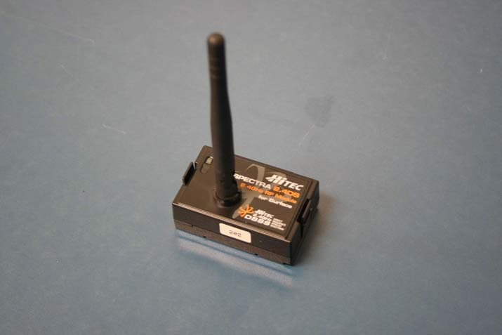
Click to zoom
Application Details
- Equipment Class
- DTS - Digital Transmission System
- Date of Grant
- Feb 21, 2010
- Application Purpose
- Original Equipment
- Date of Application
- Feb 18, 2010
- Equipment Note
- SPREAD SPECTRUM TRANSMITTER
- Frequency Range
- 2403.00000000 - 2476.00000000
- Company
- Hitec RCD Inc.
- Country
- United States
Documents & Files
Document Text
Text extracted from the exhibit documents filed with the FCC. Open a document above to read the original.
Users Manual
Atom3 Instruction SPECTRA 2.4DS: 2.4GHz DSSS Module Spec & Features Atom 3: 3 Channel Surface Receiver Specifications & Features Service & Support HITEC 2.4GHz DSSS System SPECTRA 2.4DS & ATOM 3 Instruction Manual ver 1.0 Servo manufacturer will specify maximum voltage of their servo model. Please refer each servo’s specification. Note Warning! SPECTRA 2.4DS Frequency Output Stock No. US Bandwidth 2.403GHz~2.476GHz 18dBm 28724 Japan Bandwidth 2.403GHz~2.476GHz 10dBm xxxxx Europe Bandwidth 2.403GHz~2.476GHz 10dBm xxxxx France Bandwidth 2.454GHz~2.476GHz 10dBm xxxxx Model Name Size Weight Stock Number ATOM 3 1.18 x 0.79 x 0.47in (30 x 20 x 12mm) 0.23oz(6.5g) 29324 Thank you for your purchase of the Hitec Direct Sequence Spread Spectrum or DSSS, 2.4GHz surface module and receiver system. This manual contains the complete directions on how to use the Atom3 3 channel surface receiver. We encourage you to review the entire manual before using these products. Hitec Customer Service Help is available from the Hitec office through phone support and e-mail inquiries. Our US office is generally open Monday thru Friday, 8:00AM to 4:30PM PST. These hours and days may vary by season. Every attempt is made to answer every incoming service call. Should you get voice mail, leave your name and number and a staff member will return your call.. Hitec Website Make plans to visit the Hitec website, www.hitecrcd.com, on a regular basis. Not only is it full of specs and other information about the entire Hitec product line, our FAQ pages will eventually hold valuable information and program update about the Spectra 2.4DS module and Atom 3 receiver. The On-Line Community One of the benefits of the extensive R/C online community is the vast wealth of archived knowledge available. Hitec sponsors forums on most of the popular R/C web sites where a Hitec staff member or representative tries to answer all manner of product related questions. Bringing together strangers with common interests is proving to be one of the greatest gifts of the internet. If past history is any guide to the future, we are certain forums will be started about the Hitec 2.4 system and several are certain to stand out as valuable archives of information Warranty and Non-Warranty Service All Hitec products carry a two year from date of purchase warranty against manufac- tures defects. Our trained and professional service representative will determine if the item will be repaired or replaced. To provide all the necessary information we need to administrate your repair, visit our website at www.hitecrcd.com and download the repair form, fill it out and send in your item for repair. Func. Button LED Channel & Battery Port Antenna 1. The receiver antenna should not be placed near the engine, metal parts, or high current batteries. 2. The receiver Antenna should not get damaged. To prevent antenna damage, do not install the antenna near the sharp edge or bend it more than 90 degree in angle. 3. Use a Velcro or think double sided tape to install to absolve the shock during the operation. 4. When LED indicator irregularly blinks, indicates unstable frequency environment, stop operating and look for the possible cause of problems. LED Func. Button Antenna 1177 2.403GHz ~ 2.476GHz 2.454GHz ~ 2.476GHz 1. Function/Link Button Button for Link (ID-Setting) 2. LED Status Indicator Indicates current status of module 3. Antenna 2.4GHz Rubber duck Antenna Operating Voltage: Rechargeable four to six cell NiMH, NiCd, or LiPo batteries (4.8~7.4V). From the receiver battery power or speed control (ESC) power. Select the suitable voltage depends on the servos capability. Current Consumption: 40mA 1. Function Button - Used for linking the receiver to a module and entering the FAIL-SAFE or Hold feature. 2. RED LED Status Indicator - Indicates the set-up process codes and current status of Atom 3. - Frequency environment indication feature: when the reception is bad the red LED irregularly blinks. 3. Channel Output and Battery Input Ports - The ports for battery, servos and other accessories Compatibility - The Atom3 receiver is compatible with transmitters using the Hitec DSSS 2.4 system Spectra 2.4DS module or future dedicated built-in DSSS 2.4 Hitec transmitters. What is Fail-Safe Mode? If you use the FAIL-SAFE function, and set it up properly, should the receiver signal somehow be interrupted or interference were to occurred, the servos will move to your pre-set FAIL-SAFE position you previously stored in the receiver during the FAIL-SAFE set-up. If FAIL-SAFE has not been activated, the signal is switched off after the HOLD period of 1 sec. This means that the servos become “soft” and remain in their last commanded position under no load (this may equate to full-throttle!), until a valid signal is picked up again. In the interests of safety, we recommend that FAIL-SAFE should always be activated, and the FAIL-SAFE settings should be selected so as to bring the model to a non-critical situation (e.g. motor idle / electric motor OFF, control surfaces neutral, or full brake, etc.) When LED On (Fail-Safe Mode On): Press the function button once to switch to the hold mode, the LED will goes off and indicates that the receiver is in Hold Mode. Note: once you switch to the hold mode all the saved Fail-Safe position will be deleted. When LED Off (Hold Mode On): To switch to the Fail-Safe Molde, first adjust all the control knobs to the fail-safe position you prefer, then press the function button once, the LED turns on at the same time the fail-safe position will be saved. Once Fail-Safe/Hold Selection Mode activated , you can keep switching the mode by pressing the function button. FAIL-SAFE / HOLD Option Fail-safe or Hold Mode Switch Fail-Safe Setup Method Receiver Connection Diagrams Link (ID-Setting) How to Link Spectra 2.4DS and Atom 3 receivers To avoid any interference, the link process should be done within 3 feet (1 meter) in distance. Note If FAIL-SAFE is deacti…
Text truncated - open the document above for the full version.
Cover Letter(s)
November 10, 2009 To Whom it may concern: We the undersigned, here by authorize CHUNGBUK TECHNOPARK. to act as our authorized agent on our behalf in all manners relating to application for FCC equipment authorization. including signing of all documents relating to these matters. Any individual within this entity may act on our behalf. Any and all acts carried out by CHUNGBUK TECHNOPARK. On our behalf shall have the same effect as acts of our own. This authorization is valid until further written notice from Hitec RCD Inc. Sincerely, Tony Ohm / Manager
External Photos
CHUNGBUK TECHNOPARK #685-3, Yangcheong, Ochang, Cheongwon, Chungbuk, Korea TEL:(043)270-2500 FAX:(043)270-2599 http://www.cbtp.or.kr Report Number : CBTP-10R-0005Page: 38/39 This report may not be reproduced without the full written approval of CHUNGBUK TECHNOPARK. 13. Photographs of Equipment Under Test(EUT) [Top side View]
ID Label/Location Info
CHUNGBUK TECHNOPARK #685-3, Yangcheong, Ochang, Cheongwon, Chungbuk, Korea TEL:(043)270-2500 FAX:(043)270-2599 http://www.cbtp.or.kr Report Number : CBTP-10R-0005Page: 33/39 This report may not be reproduced without the full written approval of CHUNGBUK TECHNOPARK. 11. FCC Labelling Requirements 11.1 FCC Statement Product shall be labelled the following statement in the manual: This device complies with Part 15 of the FCC Rules. Operation is subject to the following two conditions: (1) This device may not cause harmful interference, and (2) this device must accept any interference received, including interference that may cause undesired operation. When the device is so small or for such use that it is not practicable to place the statement on it, the information shall be placed in prominent location in theinstruction manual or pamphlet supplied to the user. However, the FCC identifier or unique identifier, as appropriate, must be displayed on the device. 11.2 Label & Label Location CHUNGBUK TECHNOPARK #685-3, Yangcheong, Ochang, Cheongwon, Chungbuk, Korea TEL:(043)270-2500 FAX:(043)270-2599 http://www.cbtp.or.kr Report Number : CBTP-10R-0005Page: 34/39 This report may not be reproduced without the full written approval of CHUNGBUK TECHNOPARK.
Internal Photos
CHUNGBUK TECHNOPARK #685-3, Yangcheong, Ochang, Cheongwon, Chungbuk, Korea TEL:(043)270-2500 FAX:(043)270-2599 http://www.cbtp.or.kr Report Number : CBTP-10R-0005Page: 39/39 This report may not be reproduced without the full written approval of CHUNGBUK TECHNOPARK. [Internal Photograph]
Parts List/Tune Up Info
Part NameRevPart SpecMakerQty Location SPECTRA 2.4DS (EU/KOR) INSERT PCB ASSYa SPECTRA 2.4DS (EU/KOR) INSERT PCB ASSY1 SPECTRA 2.4DS (EU/KOR) SMT PCB ASSYa SPECTRA 2.4DS (EU/KOR) SMT PCB ASSY1 SPECTRA 2.4DS (EU/KOR) SMT PCB ASSY SMD TOP a SPECTRA 2.4DS (EU/KOR) SMT PCB ASSY SMD TOP1 R Chip 1005(0402) 5% a WR04X472 JTL (WALSIN)WALSIN2 R701,R710 R Chip 1005(0402) 5% a WR04X000 JTL (WALSIN)WALSIN4 C741,C746,C734,R724 R Chip 1005(0402) 5% a WR04X103 JTL (WALSIN)WALSIN2 R702,R721 R Chip 1005(0402) 5% a WR04X101 JTL (WALSIN)WALSIN1 R716 R Chip 1005(0402) 5% a WR04X753 JTL (WALSIN)WALSIN1 R708 R Chip 1005(0402) 5% a WR04X181 JTL (WALSIN)WALSIN1 R717 R Chip 1005(0402) 5% a WR04X152 JTL (WALSIN)WALSIN1 R722 R Chip 1005(0402) 5% a WR04X752 JTL (WALSIN)WALSIN1 R725 R Chip 1005(0402) 5% a WR04X273 JTL (WALSIN)WALSIN1 R728 R Chip 1608(0603) 5%a 0 ohm 1608(0603) 5%Unknown2 L702,L703 C Ceramic Chip 1005(0402) a GRM155R71C104KA88D (MURATA Co., Ltd)MURATA Co., Ltd12 C708,C707,C716,C718,C726,C722,C728, C750,C713, C712,C709,C710 C Ceramic Chip 1005(0402) a 1nF / 25V 1005(0402)mm 10 % GRM155R71H102KA01D (MURATA Co., MURATA Co., Ltd3 C705,C743,C745 C Ceramic Chip 1005(0402) a GRM1555C1H100JZ01D (MURATA Co., Ltd)MURATA Co., Ltd7 C738,C725,C723,C727,C736,C735,C744, C Ceramic Chip 1005(0402) a GRM1555C1H3R0Z01D (MURATA Co., Ltd)MURATA Co., Ltd2 C730,C731 C Ceramic Chip 1005(0402) a GRM1555C1H1R2CZ01D (MURATA Co., Ltd)MURATA Co., Ltd1 C733 C Ceramic Chip 1005(0402) a GRM1555C1H3R6Z01D (MURATA Co., Ltd)MURATA Co., Ltd1 C737 C Ceramic Chip 1005(0402) a GRM1555C1H2R0CZ01D (MURATA Co., Ltd)MURATA Co., Ltd1 C747 L Chip 1608(0603) a LQW18AN10NG00 (MURATA Co., Ltd)MURATA Co., Ltd1 L704 L Chip 1005(0402) a LQW15AN2N7B00 (MURATA Co., Ltd)MURATA Co., Ltd1 C732 Filter Ceramic b LFB2H2G45SG7A134 (MURATA Co., Ltd)MURATA Co., Ltd2 FIL701,FIL702 Jack Others a MHC-230 (HANBIT)Unknown1 CN704 Crystal OSC SMD a CX3225SB13000F0FLJZ (KYOCERA)Unknown1 X701 Micro Controller a SST12LP15A (SST Co., Ltd.)SST Co., Ltd.1 A703 LED Chip c AOT-0603P-R01 (RED) (AOT)Unknown1 LED1 Switch Others a NJG1608KB2-TE1 (JRC)JRC1 A704 PROGRAMa SPECTRA 2.4DS (EU/KOR) REV1.01 Micro Controller a CYWUSB6953-48LFXC (Cypress)Cypress1 A702 SPECTRA 2.4DS SMT PCB ASSY SMD Bottomb SPECTRA 2.4DS SMT PCB ASSY SMD Bottom1 R Chip 1005(0402) 5% a WR04X000 JTL (WALSIN)WALSIN1 R714 R Chip 1005(0402) 5% a WR04X103 JTL (WALSIN)WALSIN1 R704 R Chip 1005(0402) 5% a WR04X102 JTL (WALSIN)WALSIN2 R713,R720 R Chip 1005(0402) 5% a WR04X473 JTL (WALSIN)WALSIN1 R709 C Ceramic Chip 1005(0402) a GRM155R71C103KA01D (MURATA Co., Ltd)MURATA Co., Ltd1 C739 C Ceramic Chip 1005(0402) a GRM155R71C104KA88D (MURATA Co., Ltd)MURATA Co., Ltd4 C751,C720,C749,C740 C Ceramic Chip 1005(0402) a GRM1555C1H100JZ01D (MURATA Co., Ltd)MURATA Co., Ltd1 C748 C Ceramic Chip 1608(0603) a 1uF 1608(0603)mm X7R 20 %SAMWHA CAPACITOR CO.4 C706,C711,C714,C715 C Ceramic Chip 3216(1206) d JMK316 BJ226ML-T (TAIYO YUDEN)TAIYO YUDEN1 C703 C Ceramic Chip 3216(1206) b EMK316 BJ106KL-T (TAIYO YUDEN)TAIYO YUDEN1 C701 C T/T Chip Ec TEESVD1A227M12R 220uF 10V D Size 20 % (NEC)Hitachi1 C702 Diode Switching Chip a BAV99WT1G (ON-SEMI Co., Ltd)ON-SEMI Co., Ltd2 D701,D702 TR BJT Chipa C1623Y-T ()Unknown1 Q701 TR BJT Chip a MMBT2907AWT1G SOT-323 (ON-SEMI Co., Ltd)ON-SEMI Co., Ltd1 Q702 OSC SMD a GPO12R000S32V33T50 (GP COM)GP COM1 OSC701 Linear Regulator a LM1117DTX-3.3 (National Instruments)National Instruments1 A701 OPAMP a NJM12904M-TE1 (JRC)Unknown1 A705 PCB Muti Layer a SPECTRA 2.4DS_REV1.0 (SUNTECH)SUNTECH1 SPECTRA 2.4DS INSERT PCB ASSY Inserta SPECTRA 2.4DS INSERT PCB ASSY Insert1 Wafer Others a MDF7-10S-2.54DSA (HIROSE KOREA)Unknown1 CON702 Switch Tack a DJT 1102K-2 (13mm) (DAEJIN INDUSTRY CO., LTD)Unknown1 SW701 2.4G TX ANTENNAc DJ-20L REV1.0 (SAEHAN ANTENNA.CO.,LTD)Shin Sung NANOTECH1 Head unita HMS-24DO /Plastic Injection /Black /PA6+GF15% /x / /10 /20JHTEC Indurstrial1 SPECTRA 2.4DS (EU/KOR) Design Seta SPECTRA 2.4DS (EU/KOR) Design Set1 SPECTRA 2.4DS /Name Plateb SPECTRA 2.4DS /37.8*31.2 /Press /Black /PCShin Sung NANOTECH1 CE_FCC_KCC Approval Sticker a SPECTRA 2.4DS /CE_FCC_KCC /15*25 /PE Shin Sung NANOTECH1 2.4DS EU stickera SPECTRA 2.4DS /EU /10*10 /NYShin Sung NANOTECH1 SPECTRA 2.4DS Mech Setc SPECTRA 2.4DS Mech Set1 Top casea HMS-24DO /Plastic Injection /Black /ABS /x / /50 /30JHTEC Indurstrial1 Bottom casea HMS-24DO /Plastic Injection /Black /ABS /x / /50 /30JHTEC Indurstrial1 Wheel Capa ZEBRA 2PA /Plastic Injection /Black /ABS /x / / /Unknown1 LENSc SPECTRA 2.4 /Plastic injection /TP /PMMA /xUnknown1 Crossed Recessed Pan Head Screwb CPH /T2 /L8 /Black /SWCH18A /BKUnknown2
RF Exposure Info
CHUNGBUK TECHNOPARK #685-3, Yangcheong, Ochang, Cheongwon, Chungbuk, Korea TEL:(043)270-2500 FAX:(043)270-2599 http://www.cbtp.or.kr Page: 1/2 1. RF Exposure Requirement 1.1 Method of Measurement This device is not exempted from compliance does notexceed the Commission’'s RF exposure guidelines. Unless a device operates at substantially low power levels, with a low gain antenna(s), supporting information is generally needed to establish the various potential operating configurations and exposure conditions of a transmitter and its antenna(s) in order to determine compliance with the RF exposure guidelines. In order to demonstrate compliance with MPE requirements (see Section 2.1091), the following information is typically needed: Calculation that estimates the minimum separation distance (20 cm or more) between an antenna and persons required to satisfy power density limits defined for free space. Antenna installation and device operating instructions for installers (professional/unskilled users), and the parties responsible for ensuring compliance with the RF exposure requirement Any caution statements and/or warning labels that are necessary in order to comply with the exposure limits Any other RF exposure related issues that may affect MPE compliance. 1.2 Limits FCC 1.1310:- The criteria listed in the following table shall be used to evaluate the environmental impact of human exposure to radio-frequency (RF) radiation as specified in 1.1307(b). Limits for Maximum Permissible Exposure (MPE) f = frequency in MHz ChannelFrequency(MHz)Power Density (mW/cm 2 ) L 2 4031.602 M 2 4401.627 H 2 4761.651 Frequency range (MHz) Electric Field Strength (V/m) Magnetic Field Strength (A/m) Power Density (mW/cm 2 ) Average Time (minutes) (B) Limits for General Population/Uncontrolled Exposure 300-1500--f / 1 50030 CHUNGBUK TECHNOPARK #685-3, Yangcheong, Ochang, Cheongwon, Chungbuk, Korea TEL:(043)270-2500 FAX:(043)270-2599 http://www.cbtp.or.kr Page: 2/2 1.3 Test Results Frequency [MHz] Conducted Power [dBm] Antenna Gain [dBi] Calculated EIRP [mW] Laboratory’s Recommended Minimum RF Safety Distance r [Cm] Power Density in mW/cm 2 at Formula When r=20Cm [mW/cm 2 ] 2 40316.632.2977.985.570.015 5 2 44016.002.7374.645.450.014 9 2 47615.232.3557.284.770.011 4 Calculation Method of RF Safety Distance: S= 22 44r EIRP r PG ππ = P : power input to the antenna in mW EIRP: Equivalent (effective)isotropic radiated power. S : power density mW/cm 2 G : numeric gain of antenna relative to isotropic radiator R : distance to centre of radiation in cm FCC radio frequency exposure limits may be exceededat distances closer than r cm from the antenna of this device r= S EIRP S PG ππ44 =
RF Exposure Info
안 테 나 승 인 원 안테나 종류 Dipole Antenna 모 델 명 DJ-20L 적용모델 담 당 검 토 승 인 결 재 (주) 새 한 안 테 나 목 차 1. 규 격 ............................................3. 1.1. 일반 규격 1.2. 전기적 규격 1.3. 기계적 규격 1. 4. 전기적 특성 검사 2. 기구적 특성 시험 ...........................................7 2. 1. 외관치수 2.2. 인장강도 2. 3. 컨넥터 삽입 시험 3. 환 경 성 시 험 .......................................9 3.1. 고온 고습 시험 3. 2. 염수분무 시험 3. 3. 낙하 시험 4. 제조 및 품질관리 공정도 ....................................11 5. 제품 포장 ....................................12 1. 규 격(Specification) 1.1. 일반 규격 General specification Model name DJ – 20L Antenna type 1/2 Wavelength Dipole Antenna 1.2. 전기적 규격 Electrical specification Frequency Range 2.4 ~ 2.5GHz V.S.W.R Less Than 1.5 Gain(dBi) 2.35dBi (Max) Radiation pattern Omni-directional Polarization Linear Vertical Impedance 50Ω Normal ± 10 1.3. 기계적 규격 Mechanical specification Connector Type U.FL Mail Cover Material 도면참조 Color Black Temperature Range -45°C ~ +85°C Weight 8g ± 0.2g Dimension 도면참조 1. 4 전기적 특성검사 가) Network Analyzer 검사 ① Network Analyzer 사양 장 비 명 Model 규 격 Network Analyzer HP8753ES · Freq. Range : 300KHz ~ 6GHz Calibration Kit HP85032B · DC ~ 6GHz (SMA-Type) ② 네트워크 검사 모형도 그림 1. Network Analyzer 검사 시 계측기 연결도 ③ 시험 방법 : 상기 그림과 같이 안테나를 연결하고 2.4 – 2.5GHz, CF : 2.45GHz에서 V.S.W.R 값을 측정한다. ④ 시험 요구 사항 : 상기 주파수에서 V.S.W.R 값이 2.0 이하를 만족하여야 함 ⑤ 시험 결과 : 하기 데이터와 같이 상기 조건을 만족함 ⑥ 측정 DATA 그림 2. V.S.W.R 측정 데이터 주 파 수 V.S.W.R 비 고 2.40GHz 1.30 2.45GHz 1.10 2.50GHz 1.19 나) Antenna Anechoic Chamber 검사 ① Chamber 사양 구 분 규 격 Chamber Size 5(L)m X 5.5(W)m X 5(H)m Frequency Range 800MHz – 6GHz (Far Field) Quiet Zon 1 X 1m @ 1GHz Type Rectangular 피측정 안테나 무게 < 50 kg ② 챔버 측정 모형도 그림 3. 챔버 구성도 ③ 시험 방법 : 상기 그림과 같이 안테나를 측정한다 ④ 시험 요구 사항 : 2.4 – 2.5GHz 에서 안테나 Gain 값 측정 ⑤ 시험 결과 : 하기 그림과 같이 상기 요구사항을 만족함 Positioner Control Microwave Receiver Printe r Roll Positioner GPIB RF Cables S ystem Cable Far Field Measurement Software System Controller Az/El/Az Positioner Antenna Under Test Standard Gain Horn Antenna ⑥ Gain 및 Beam Pattern 도 그림 4. Gain 및 방사패턴도 주 파 수 Gain(Max) 비 고 2.40GHz 2.29dBi 2.45GHz 2.35dBi 2.50GHz 2.08dBi E-Plane 주 파 수 Gain(Max) 비 고 2.40GHz 0.92dBi 2.45GHz 1.37dBi 2.50GHz 1.79dBi 2 . 기구적 특성시험 2.1 외관치수 가) 시험 방법 : 안테나를 Vernier Calipers로 치수 측정 나) 시험 요구사항 : 치수는 하기 도면과 일치할 것. 다) 시험 결과 : 도면과 일치함 라) 도 면 그림 5 안테나 도면 2.2. 인장력(본딩상태)시험 가) 시험방법 : 안테나를 고정 후 Tension Gauge로 최대한 당겨 파괴부위와 힘을 수치 체크한다. 나) 시험 요구 사항 : 안테나 인장력은 100gf 이상을 만족 해야 함 다) 시험 결과 : 위 요구 사항을 만족함 2.3. 컨넥터 시험 가) 시험 방법 : 상대물에 안테나 컨넥터를 고정하여 적합 지그로 100회 착탈을 실시한다. 나) 시험 요구 사항 : 100회 시험 후 삽입력 유지 다) 시험 결과 : 위 요구 사항을 만족함 3. 환경 시험 3.1 고온 고습 시험 가) 시험 조건 : 항온 항습기에 -40°C ~ +85°C 에서 50%RH (10회) 나) 시험 방법 : 시료를 항온 항습기에 넣고 상기 시험 조건에 따라 시험 다) 시험 요구사항 : 제품의 외관 (크랙,변형,변색)상의 이상이 없어야 함 라) 온도 Cycling 그림 6. 온도 사이클링 마) 시험 결과 : 위 요구 사항을 만족함 3.2. 염수 분무 시험 가) 시험 조건 : 시험 기기에 온도 35±2°C,염수농도 5%의 중량비.염수 KSM8115의 1급품 증류수 200ppm 이하의 순수물, 분무압력 68.6-176.4 kpa(kN/m2) 나) 시험 방법 : ① 상기 시험 조건에 의거 72시간 동안 방치 ② 시험이 완료 후 10분 이내에 상온의 유수로 염수와 습기 제거 다) 시험 요구사항 : 상온 상습에서 24시간 방치 후 외관 및 전기적 성능 만족해야 함 라) 시험 결과 : 위 요구 사항을 만족함 3.3. 낙하 시험 가) 시험 조건 : 낙하 높이 : 1 m 나) 시험 방법 : 바닥표면이 콘크리트 구조로 된 1m 높이에서 수직으로 10회 낙하 다) 시험 요구 사항 : 기계적 특성과 전기적 특성 손상이 없어야 함 라) 시험 결과 : 위 요구 사항을 만족함 4. 제조 및 품질관리 공정도 순 서 작업공정 사용설비 품질관리항목 규 격 검사설비 검사방식 비 고 1 컨넥터 외주구입 치수 도면과 일치 치구검사 자주검사 2 Ground Plane 자동선반 치수 도면과 일치 치구검사 자주검사 3 가 공 케이블 탈피 자동탈피 기 치수 도면과 일치 치구검사 수입검사 4 슬리브외2종 사 출 기 외관 흠집 목시검사 전수검사 5 사 출 사출 세척 수작업 세척 상태 6 조인트+파이프 지그 7 조인트 결합 수작업 본딩상태 분리여부 수검사 전수검사 8 핀결합 2회 지그 조립 상태 분리여부 수검사 전수검사 9 조 립 G.P+케이블 지그 조립 상태 분리여부 수검사 전수검사 10 튜 닝 계측기 튜닝 N / A V.S.W.R 2.0이하 N / A 전수검사 11 본 딩 슬리브+조인트 수작업 본딩상태 수검사 전수검사 12 계측기 검사 N / A V.S.W.R 2.0이하 N / A 전수검사 13 검 사 출하검사 수작업 외관 외관상태 목시검사 전수검사 14 포장 수작업 포장사양일치 목시검사 출하검사 5. 포장 사양 가) 포장 방법 : 1차 포장 : 개별로 비닐 팩 포장을 한다 2차 포장 : 1박스에 1,000개씩 포장을 한다
Test Report
CHUNGBUK TECHNOPARK #685-3, Yangcheong, Ochang, Cheongwon, Chungbuk, Korea TEL:(043)270-2500 FAX:(043)270-2599 http://www.cbtp.or.kr Report Number : CBTP-10R-0005 Page: 2/39 This report may not be reproduced without the full written approval of CHUNGBUK TECHNOPARK. TABLE OF CONTENTS 1. Test Laboratory ······················································································································· 3 1.1 General Information ········································································································································ 3 1.2 Location of Test Laboratory ························································································································· 3 1.3 Registration Information ································································································································· 3 2. Test Rule ································································································································· 4 2.1 Test Rule Part(s) ············································································································································ 4 2.2 Equipment Under Test(EUT) Modifications ································································································ 4 3. Description for Equipment Under Test(EUT) ····································································· 5 4. Test Equipment ······················································································································· 6 5. 6 dB bandwidth ······················································································································ 7 6. maximum peak conducted output power ··········································································· 10 7. antenna requirement ·············································································································· 13 8. 100 kHz bandwidth outside the frequency band ······························································ 14 9. power spectral density conducted ······················································································· 24 10. Radiated Emissions ············································································································· 27 11. FCC Labelling Requirements ···························································································· 33 12. Test Setup Photographs ······································································································35 13. Photographs of Equipment Under Test(EUT) ································································· 38 CHUNGBUK TECHNOPARK #685-3, Yangcheong, Ochang, Cheongwon, Chungbuk, Korea TEL:(043)270-2500 FAX:(043)270-2599 http://www.cbtp.or.kr Report Number : CBTP-10R-0005 Page: 3/39 This report may not be reproduced without the full written approval of CHUNGBUK TECHNOPARK. 1. Test Laboratory 1 . 1 Ge ne ral Inf o rmati o n Name of LaboratoryCHUNGBUK TECHNOPARK RepresentativeJongsung, Lim Address 685-1 Yangcheong-ri, Ochang-eup, Cheongwon-gun, Chungcheongbuk-do, Korea Telephone Number043-270-2000 Fax Number043-270-2099 Homepagewww.cbtp.or.kr 1.2 Location of Test Laboratory Address 685-3 Yangcheong-ri, Ochang-eup, Cheongwon-gun, Chungcheongbuk-do, Korea Telephone Number043-270-2500 Fax Number043-270-2599 1.3 Registration Information Test item(s)FacilityRegistration Number Radiated Emission Measurement10m semi-anechoic chamber 647924 Conducted Emission MeasurementShielded room CHUNGBUK TECHNOPARK #685-3, Yangcheong, Ochang, Cheongwon, Chungbuk, Korea TEL:(043)270-2500 FAX:(043)270-2599 http://www.cbtp.or.kr Report Number : CBTP-10R-0005 Page: 4/39 This report may not be reproduced without the full written approval of CHUNGBUK TECHNOPARK. 2. Test Rule 2.1 Test Rule Part(s) Test item(s)Test Rule Part(s)Test Result 1. 6 dB bandwidth15.247 (a)(2) ■ Pass□ Fail 2. maximum peak conducted output power15.247 (b)(3) ■ Pass□ Fail 3. antenna requirement 15.247 (b)(4) 15.203 ■ Pass□ Fail 4. 100 kHz bandwidth outside the frequency band15.247 (d) ■ Pass□ Fail 5. power spectral density conducted15.207 (e) ■ Pass□ Fail 6. Radiated emissions 15.247(d) 15.209(a) 15.205(a) ■ Pass□ Fail 2.2 Equipment Under Test(EUT) Modifications No modifications were made to the EUT in order to achieve and maintain compliance to the standards described in this report. CHUNGBUK TECHNOPARK #685-3, Yangcheong, Ochang, Cheongwon, Chungbuk, Korea TEL:(043)270-2500 FAX:(043)270-2599 http://www.cbtp.or.kr Report Number : CBTP-10R-0005 Page: 5/39 This report may not be reproduced without the full written approval of CHUNGBUK TECHNOPARK. 3. Description for Equipment Under Test(EUT) Specification of Module 1. Model : Spectra 2.4DS 2. Module use section : Surface 3. Frequency : 2.403㎓ ~ 2.476㎓ (74Channel) 4. Channel spacing : 1MHz 5. Spreading bandwidth : 500 kHz 6. Communication Speed : 16Kbps 10. RF power : 50㎽ 8. Operating Voltage : Battery 8Cells (9.6V) 9. Operating Temperature : -20°C ~ +60°C 12. Drain Current : 150mA 13. Modulation : DSSS CHUNGBUK TECHNOPARK #685-3, Yangcheong, Ochang, Cheongwon, Chungbuk, Korea TEL:(043)270-2500 FAX:(043)270-2599 http://www.cbtp.or.kr Report Number : CBTP-10R-0005 Page: 6/39 This report may not be reproduced without the full written approval of CHUNGBUK TECHNOPARK. TypeModelManufactureS/NCAL. Due PSA Spectrum AnalyzerE4440AAgilent TechnologiesMY461865192010.04.23 Programmable Switching D.C Power Supply PSH-2050AGW InstekEH1608242010.04.23 EMI ReceiverLSA-265LIG Nex1L071180382010.04.25 Horn AntennaBBHA9120DSchwarzbeck9120D-5392010.03.24 Horn AntennaBBHA9120DSchwarzbeck9120D-5402010.03.24 Horn AntennaBBHA9170Schwarzbeck9170-3162010.03.06 Horn AntennaBBHA9170Schwarzbeck9170-3172010.05.02 BiLog AntennaVULB9163Schwarzbeck2622010.06.13 BiLog AntennaVULB9163Schwarzbeck2632010.06.13 10m semi-anechoic chamber…
Text truncated - open the document above for the full version.
Test Setup Photos
CHUNGBUK TECHNOPARK #685-3, Yangcheong, Ochang, Cheongwon, Chungbuk, Korea TEL:(043)270-2500 FAX:(043)270-2599 http://www.cbtp.or.kr Report Number : CBTP-10R-0005Page: 35/39 This report may not be reproduced without the full written approval of CHUNGBUK TECHNOPARK. 12. Test Setup Photographs 12.1 Radiated Emission Measurement, 30 MHz to 1000 MHz [Front View] [Rear View] CHUNGBUK TECHNOPARK #685-3, Yangcheong, Ochang, Cheongwon, Chungbuk, Korea TEL:(043)270-2500 FAX:(043)270-2599 http://www.cbtp.or.kr Report Number : CBTP-10R-0005Page: 36/39 This report may not be reproduced without the full written approval of CHUNGBUK TECHNOPARK. 12.2 Radiated Emission Measurement, 1.0 GHz to 18.0 GHz [Front View] [Rear View] CHUNGBUK TECHNOPARK #685-3, Yangcheong, Ochang, Cheongwon, Chungbuk, Korea TEL:(043)270-2500 FAX:(043)270-2599 http://www.cbtp.or.kr Report Number : CBTP-10R-0005Page: 37/39 This report may not be reproduced without the full written approval of CHUNGBUK TECHNOPARK. 12.3 Radiated Emission Measurement, 18.0 GHz to 26.5 GHz [Front View] [Rear View]
Contact Information
Applicant
Tony Ohm(Service Dept. Manager)
Test Firm
CHUNGBUK TECHNOPARKSeong-Uk Park
Technical Specifications
| # | Rule Parts | Frequency Range | Power Output |
|---|---|---|---|
| 1 | 15C | 2.40 GHz - 2.48 GHz | 50.00 mW |
Other Applications from Hitec RCD Inc.
IFHRX57MLINK
Dec 22, 20147 CHANNEL 2.4 GHz TRANSCEIVER
Equipment Class
DSS - Part 15 Spread Spectrum Transmitter
IFHRX5MLINK
Dec 16, 2014RX5 M-LINK CHANNEL 2.4 GHz TRANSCEIVER
Equipment Class
DXX - Part 15 Low Power Communication Device Transmitter
IFHSMART-SX
Sep 16, 20146 CHANNEL 2.4 GHz RADIO CONTROL TRANSMITTER
Equipment Class
DSS - Part 15 Spread Spectrum Transmitter
IFHLYNX4S
Jul 22, 20142.4GHz Radio Control System
Equipment Class
DSS - Part 15 Spread Spectrum Transmitter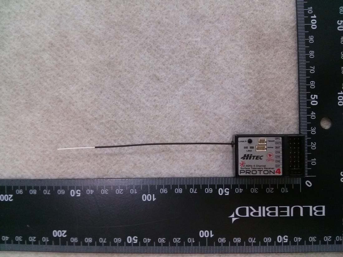
IFHPROTON4
Jul 22, 20142.4GHz Radio Control System
Equipment Class
DSS - Part 15 Spread Spectrum Transmitter