IFHSPECPRO-72RADIO CONTROL HOBBY TRANSMITTER
Hitec RCD Inc.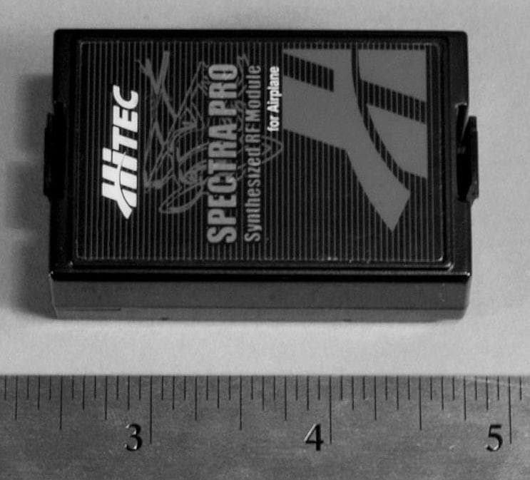
Click to zoom
Application Details
- Equipment Class
- TNB - Licensed Non-Broadcast Station Transmitter
- Date of Grant
- Feb 27, 2011
- Application Purpose
- Original Equipment
- Date of Application
- Feb 27, 2011
- Equipment Note
- RADIO CONTROL HOBBY TRANSMITTER
- Frequency Range
- 72.01000000 - 72.99000000
- Company
- Hitec RCD Inc.
- Country
- United States
Documents & Files
Document Text
Text extracted from the exhibit documents filed with the FCC. Open a document above to read the original.
Users Manual
2. Installing the Steel Antenna into the transmitter a. Insert the steel antenna into the antenna hole of the Aurora 9, and turn it to the clock wise direction to tighten up. b. Turn the antenna clockwise until it is securely screwed into the transmitter. Range Check Function Before each flight, it is critical that you perform a range check to confirm the signal between the receiver and transmitter is appropriate. Unlike 2.4GHz system the FM/PPM or PCM radios, use an extendable steel antenna. Therefore, the method of range check has to be different. Lower the transmitter antenna all the way to reduce the transmitter signal range to minimum level. Once the antenna collapsed it will shortening the range to approximately 30 meters or 100 feet. During the range check process, you should walk away from the secured aircraft carrying the transmitter to a minimum distance of approximately 30 meters or 100 feet without control loss. Warning! - Do the range check before each flying session to confirm the radio system is working properly. - Do the range check before the engine or motor is started. - Turn on the system as explained above and make sure all servos and control surfaces are working properly during the range check process within the range. - If any control surface is not moving properly, DO NOT fly the aircraft until the problem is solved. - If you are unable to accomplish a successful range check of 30 meters or 100 feet, DO NOT ATTEMPT TO FLY. Connecting (Frequency Setting) Spectra Pro uses synthesize technology does not require classic crystal chips to change its frequencies. Plug into the Aurora 9 transmitter and select your preferred Frequency Channel matches with your receivers. In the case of multiple models are being used from one transmitter, you can connect as many Hitec receivers to your transmitter as necessary, one model per one model memory will be used. Use one of the following connecting meth- ods to add additional Hitec receivers to your transmitter. Note - Connecting must be established within 15 feet of the transmitter and receiver. - Make sure there is no one next to you are in connecting process. - In case of synthesized receiver is being used for the connecting process, setup the frequency channel from the Aurora 9 first then turn on the receiver. Again, we really appreciated for your purchase of Spectra Pro FM Synthe sized Module, and hope you to enjoy all the great feature of Aurora 9 with your FM series receivers. secure the aircraft and walk away approximatery 30meter without control loss 30 meter or 100 feet General Use Guidelines General Use Guidelines To turn the system on and off, use the following sequence at all times. Transmitter Antenna Installation The conventional steel antenna (included with the module) required to install prior to use. You are required to remove 2.4GHz antenna and the antenna holder before the installation. 1. Disassembling the Antenna Mount and Folding Antenna a. Snap the antenna apart as shown in picture #1. Carefully remove the mod ule from the back of the Aurora 9 transmitter. b. Remove the antenna mount from the transmitter by turning it to the counter clock wise direction. Introduction Thank you for your purchase of the Hitec Synthesized 72MHz PCM/PPM Spectra Pro Module for Aurora 9. This manual contains the complete directions on how to install and use the module and the receiver with Aurora 9 transmitter. We encourage you to review the entire manual before using these products. Service & Support Hitec Customer Service Help is available from Hitec customer service through phone support and e-mail inquiries. Our US office is open Monday thru Friday, 8:00AM to 4:30PM PST. These hours and days may vary by season. We make every attempt to answer all incoming service calls; should you reach our voicemail, please leave your name and number and a staff member will promptly return your call. Hitec Website We invite you to regularly visit our website at www.hitecrcd.com for specification information and descriptions of our entire product line. Our FAQ pages provide valuable information as well as program updates on the radio, module, receiver, and other update available products. The On-Line Community One of the benefits of the extensive RC on-line community is the vast wealth of archived information available. Hitec sponsors forums on most of the popular RC websites where a Hitec staff member or representative answers product-related questions. Bringing together strangers with common interests is proving to be one of the greatest gifts of the internet. If past history is any guide to the future, we are certain forums will be started about the Hitec system creating valuable archived information for future access. Warranty and Non-Warranty Service All Hitec products carry a two-year warranty against manufacturing defects from date-of- purchase. Our trained, professional service representative will determine if the item will be repaired or replaced. Please complete and include the repair form at www.hitecrcd.com when you return your item so that we may administer your repair promptly. Hitec Service 12115 Paine St. Poway CA 920641-858-748-6948 E-mail: [email protected] Warning! 1. For maximum performance, we recommend the antenna to be extended to its maximum length. 2. The receiver antenna should not be placed near the engine, metal parts or high current batteries. 3. Depending on flying conditions, you may possibly experience shorten in flight range and unstable flying condition. Please make sure to check and eliminate all the possible problem causes before each flight. SPECTRA PRO Module Features Synthesized 72MHz PCM/PPM ModuleStock # 23772 1. Spectra Pro Module - A synthesized RF module, Spectra Pro supports 72MHz PCM/PPM band width. Simply plug in the module to Aurora 9 transmitter and link with the Hitec receivers. 2. Transmitter Antenna - To use Spectra Pro with Aurora 9, conventional steel transmitter antenna is required. * St…
Text truncated - open the document above for the full version.
Block Diagram
5 5 4 4 3 3 2 2 1 1 DD CC BB AA Title SizeDocument NumberRev Date:Sheetof <Doc> a Spectra pro 72M Block Diagram A4 11Wednesday, December 01, 2010 Title SizeDocument NumberRev Date:Sheetof <Doc> a Spectra pro 72M Block Diagram A4 11Wednesday, December 01, 2010 Title SizeDocument NumberRev Date:Sheetof <Doc> a Spectra pro 72M Block Diagram A4 11Wednesday, December 01, 2010 Atmega 48V Control Frequency BU2630FV PLL CONTROLLER MODULATOR FREQUENCY MULTIPLIER POWER AMPLIFIER LOW FILTER PASS REGULATOR VOLTAGE 5VVCC
External Photos
2115 Paine Street, Poway, CA 92064 TEL (858) 748-6948 FAX (858) 748-1767 WWW.HITECRCD.COM HITEC RCD USA, Inc External Photographs View From Front 2115 Paine Street, Poway, CA 92064 TEL (858) 748-6948 FAX (858) 748-1767 WWW.HITECRCD.COM HITEC RCD USA, Inc External photographs View Of Back 2115 Paine Street, Poway, CA 92064 TEL (858) 748-6948 FAX (858) 748-1767 WWW.HITECRCD.COM HITEC RCD USA, Inc External Photographs View Of Side 2115 Paine Street, Poway, CA 92064 TEL (858) 748-6948 FAX (858) 748-1767 WWW.HITECRCD.COM HITEC RCD USA, Inc External Photographs View Of Side 2115 Paine Street, Poway, CA 92064 TEL (858) 748-6948 FAX (858) 748-1767 WWW.HITECRCD.COM HITEC RCD USA, Inc External Photographs Assembled in R/C Controller
ID Label/Location Info
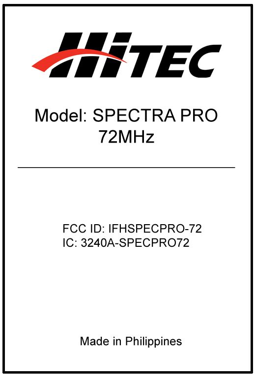
01/03/2011 Label Sample Label Placement HITEC RCD USA, LLC 12115 Paine Street, Poway CA 92064 TEL(858)748-6948 FAX(858)748-1767 WWW.HITECRCD.COM
Internal Photos
2115 Paine Street, Poway, CA 92064 TEL (858) 748-6948 FAX (858) 748-1767 WWW.HITECRCD.COM HITEC RCD USA, Inc Internal Photographs Internal View with Shield 2115 Paine Street, Poway, CA 92064 TEL (858) 748-6948 FAX (858) 748-1767 WWW.HITECRCD.COM HITEC RCD USA, Inc Internal Photographs Internal View with Shield 2115 Paine Street, Poway, CA 92064 TEL (858) 748-6948 FAX (858) 748-1767 WWW.HITECRCD.COM HITEC RCD USA, Inc Internal Photographs Internal View with Shield Removed 2115 Paine Street, Poway, CA 92064 TEL (858) 748-6948 FAX (858) 748-1767 WWW.HITECRCD.COM HITEC RCD USA, Inc Internal Photographs Top Side View of Main Board 2115 Paine Street, Poway, CA 92064 TEL (858) 748-6948 FAX (858) 748-1767 WWW.HITECRCD.COM HITEC RCD USA, Inc Internal Photographs Bottom Side View of Main Board
Parts List/Tune Up Info
RF adjustment using JIG. 1. Connect Power supply(7.2V) to the JIG. Also connect WATT meter to JIG. Watt meter setting is 300mW. 2.Insert Spectra Pro to the JIG. Turn ON the power of the JIG. 3.Check frequency if it is in correct setting. 4.Click on YES. 5.Adjust RFT coil to maximum RF. Follow sequence in the picture. Repeat the procedure to get the maximum RF. 1 2 34 RF adjustment using JIG. 6.Turn OFF power of JIG, remove module. Repeat step 2 for the next unit. RF adjustment using Aurora 9. 1. Turn On power of Aurora 9. 2. Click YES. 3. Adjust each RFT coil to maximum RF. Follow sequence in the picture. Repeat this process until you get the maximum RF. 4. Check for the RF status (bounding fail). Re- adjust RFT coil again when encounter this problem. 1 2 34 RF adjustment using Aurora 9. 5. Check for the wave display after RF adjustment. 6. Adjust modulation by adjusting the TRIMMER. SPECS: 2.8 KHz +/- 0.3 KHz 7. Adjust Frequency by adjusting the TRIMMER.
Test Report
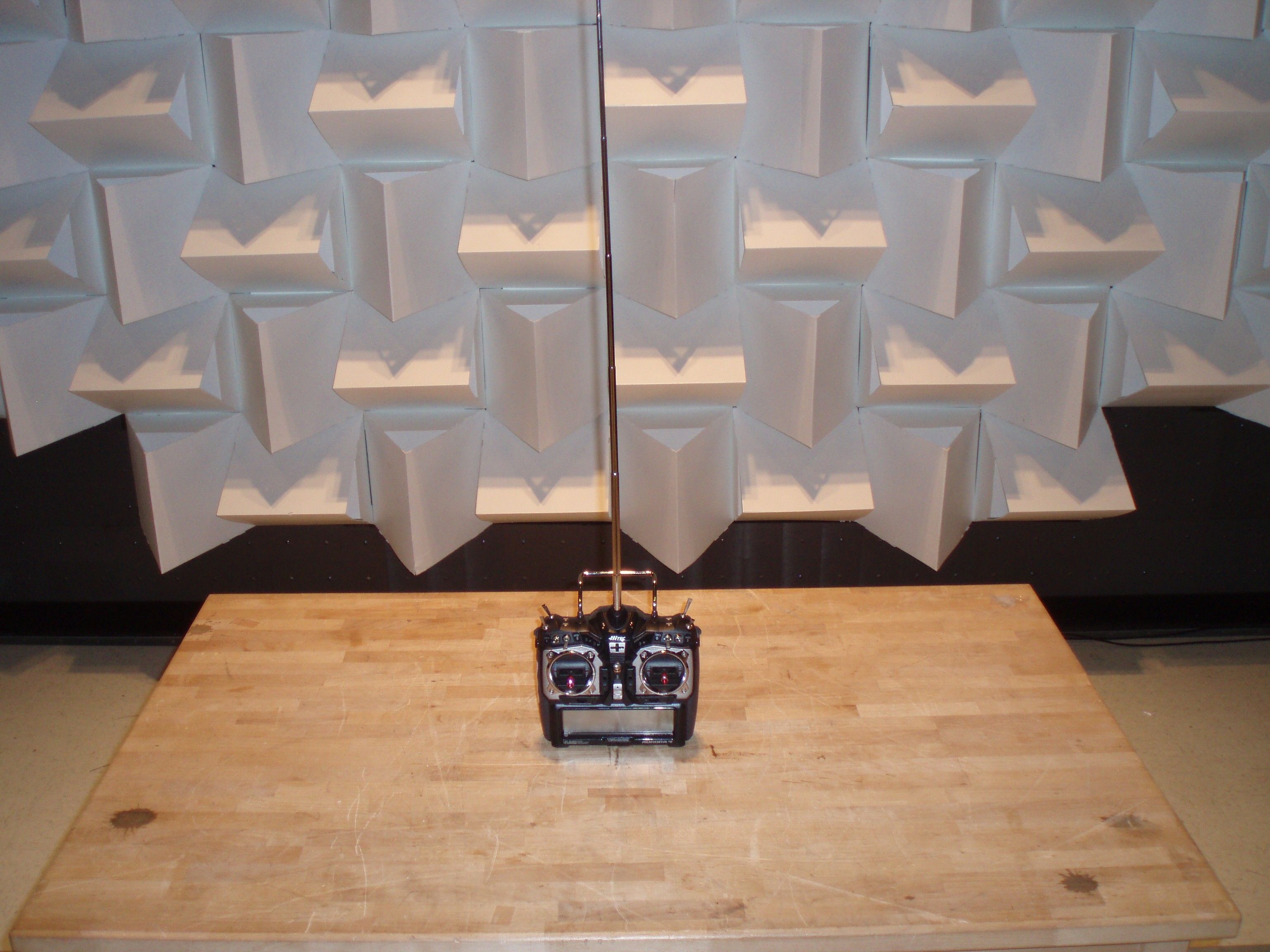
FCC PART 95 SUBPART C AND IC RSS-210 TEST REPORT FOR REMOTE CONTROL TRANSMITTERS APPLICANT HITEC RCD INC. 12115 PAINE STREET POWAY CALIFORNIA 92064 USA FCC ID IFHSPECPRO-72 IC 3420A-SPECPRO72 MODEL NUMBER SPECTRA PRO PRODUCT DESCRIPTION RADIO CONTROL HOBBY TRANSMITTER DATE SAMPLE RECEIVED January/13/2011 DATE TESTED February/1/2011 TESTED BY JOSEPH SCOGLIO APPROVED BY MARIO R. DE ARANZETA TIMCO REPORT NO. 94AT11TestReport.doc TEST RESULTS PASS FAIL THE ATTACHED REPORT SHALL NOT BE REPRODUCED EXCEPT IN FULL WITHOUT THE WRITTEN APPROVAL OF TIMCO ENGINEERING, INC. 849 NW STATE ROAD 45 NEWBERRY, FL 32669 USA PH: 888.472.2424 OR 352.472.5500 FAX: 352.472.2030 EMAIL: [email protected] HTTP: //WWW.TIMCOENGR.COM Testing Certificate # 0955-01 APPLICANT: HITEC RCD INC. FCC ID: IFHSPECPRO-72 IC: 3420A-SPECPRO72 REPORT #: H\HITEC_IFH\94AT11\94AT11TestReport.doc Page 2 of 15 TABLE OF CONTENTS GENERAL REMARKS ................................................................................................. 3 GENERAL INFORMATION .......................................................................................... 4 TEST ENVIRONMENT ................................................................................................ 5 TEST SETUP SUMMARY ............................................................................................ 5 EQUIPMENT LIST ...................................................................................................... 6 TEST PROCEDURE ................................................................................................... 7 RF POWER OUTPUT .................................................................................................. 8 MODULATION CHARACTERISTICS ............................................................................ 9 OCCUPIED BANDWIDTH ......................................................................................... 10 SPURIOUS EMISSIONS AT ANTENNA TERMINALS (CONDUCTED) ........................... 12 FIELD STRENGTH OF SPURIOUS EMISSIONS ......................................................... 13 FREQUENCY STABILITY .......................................................................................... 15 APPLICANT: HITEC RCD INC. FCC ID: IFHSPECPRO-72 IC: 3420A-SPECPRO72 REPORT #: H\HITEC_IFH\94AT11\94AT11TestReport.doc Page 3 of 15 GENERAL REMARKS The attached report shall not be reproduced except in full without the written permission of Timco Engineering Inc. The test results relate only to the items tested. Summary The device under test does: fulfill the general approval requirements as identified in this test report not fulfill the general approval requirements as identified in this test report Attestations This equipment has been tested in accordance with the standards identified in this test report. To the best of my knowledge and belief, these tests were performed using the measurement procedures described in this report. All instrumentation and accessories used to test products for compliance to the indicated standards are calibrated regularly in accordance with ISO 17025 requirements. Testing Certificate # 0955-01 I attest that the necessary measurements were made, under my supervision, at: Timco Engineering Inc. 849 NW State Road 45 Newberry, Fl 32669 Authorized Signatory Name: Mario de Aranzeta C.E.T. Compliance Engineer/ Lab. Supervisor Date: February/1/2011 APPLICANT: HITEC RCD INC. FCC ID: IFHSPECPRO-72 IC: 3420A-SPECPRO72 REPORT #: H\HITEC_IFH\94AT11\94AT11TestReport.doc Page 4 of 15 GENERAL INFORMATION DUT Specification DUT Description RADIO CONTROL HOBBY TRANSMITTER FCC ID IFHSPECPRO-72 Model Number SPECTRA PRO Serial Number N/A Operating Frequency 72.01 - 72.99 MHz Type of Emission 8K0F1D DUT Power Source 110–120Vac/50– 60Hz DC Power Battery Operated Exclusively Test Item Prototype Pre-Production Production Type of Equipment Fixed Mobile Portable APPLICANT: HITEC RCD INC. FCC ID: IFHSPECPRO-72 IC: 3420A-SPECPRO72 REPORT #: H\HITEC_IFH\94AT11\94AT11TestReport.doc Page 5 of 15 TEST ENVIRONMENT Test Facility Timco Engineering, Inc. 849 NW State Road 45 Newberry, FL 32669 USA. Test Condition in the laboratory Temperature: 26ºC Relative humidity: 50% TEST SETUP SUMMARY Test Setup Diagram/ Description The DUT was placed on the turntable per setup per ANSI C63.4: 2003. A test set up photo is provided for clarification. Deviation from the standard/procedure No deviation Modification of DUT No modification Applicable Standards EIA/TIA-382-A, FCC CFR 47 PART 95, IC RSS-210 APPLICANT: HITEC RCD INC. FCC ID: IFHSPECPRO-72 IC: 3420A-SPECPRO72 REPORT #: H\HITEC_IFH\94AT11\94AT11TestReport.doc Page 6 of 15 EQUIPMENT LIST Device Manufacturer Model Serial Number Cal/Char Date Due Date 3-Meter Semi- Anechoic Chamber Panashield N/A N/A Listed 3/10/10 3/10/12 AC Voltmeter HP 400FL 2213A14499 CAL 3/23/09 3/23/11 Antenna: Dipole Kit Electro- Metrics TDA-30/1-4 153 CHAR 6/10/09 6/10/11 Frequency Counter HP 5385A 3242A07460 CAL 5/26/09 5/26/11 Hygro- Thermometer Extech 445703 0602 CAL 1/30/09 1/30/11 Modulation Analyzer HP 8901A 3435A06868 CAL 5/26/09 5/26/11 Digital Multimeter Fluke FLUKE-77-3 79510405 CAL 5/18/09 5/18/11 Analyzer Tan Tower Preamplifier HP 8449B-H02 3008A00372 CAL 11/21/09 11/21/11 Analyzer Tan Tower Quasi- Peak Adapter HP 85650A 3303A01690 CAL 11/22/09 11/22/11 Analyzer Tan Tower RF Preselector HP 85685A 3221A01400 CAL 11/21/09 11/21/11 Analyzer Tan Tower Spectrum Analyzer HP 8566B Opt 462 3138A07786 3144A20661 CAL 11/24/09 11/24/11 Temperature Chamber Tenney Engineering TTRC 11717-7 CHAR 4/25/10 4/25/12 APPLICANT: HITEC RCD INC. FCC ID: IFHSPECPRO-72 IC: 3420A-SPECPRO72 REPORT #: H\HITEC_IFH\94AT11\94AT11TestReport.doc Page 7 of 15 TEST PROCEDURE Power Line Conducted Interference: The procedure used was EIA/TIA-382-A using a 50uH LISN. Both lines were observed with the UUT transmitting. The bandwidth of the spectrum analyzer was 10 kHz with an appropriate sweep speed. Bandwidth 20 dB: The measure…
Text truncated - open the document above for the full version.
Contact Information
Applicant
Tony Ohm(Service Dept. Manager)
Test Firm
Timco Engineering, Inc.Bruno Clavier
Technical Specifications
| # | Rule Parts | Frequency Range | Power Output | Emission | Tolerance |
|---|---|---|---|---|---|
| 1 | 95C | 72.01 MHz - 72.99 MHz | 26.00 mW | 8K0F1D | 20.0000000000 ppm |
Other Applications from Hitec RCD Inc.
IFHRX57MLINK
Dec 22, 20147 CHANNEL 2.4 GHz TRANSCEIVER
Equipment Class
DSS - Part 15 Spread Spectrum Transmitter
IFHRX5MLINK
Dec 16, 2014RX5 M-LINK CHANNEL 2.4 GHz TRANSCEIVER
Equipment Class
DXX - Part 15 Low Power Communication Device Transmitter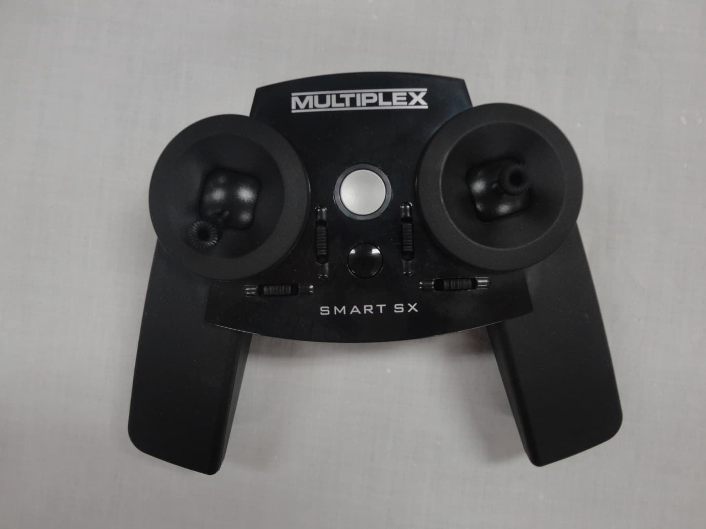
IFHSMART-SX
Sep 16, 20146 CHANNEL 2.4 GHz RADIO CONTROL TRANSMITTER
Equipment Class
DSS - Part 15 Spread Spectrum Transmitter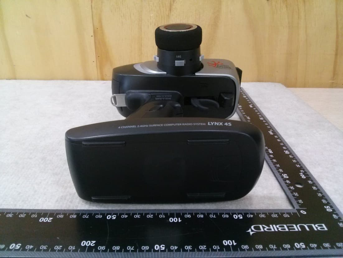
IFHLYNX4S
Jul 22, 20142.4GHz Radio Control System
Equipment Class
DSS - Part 15 Spread Spectrum Transmitter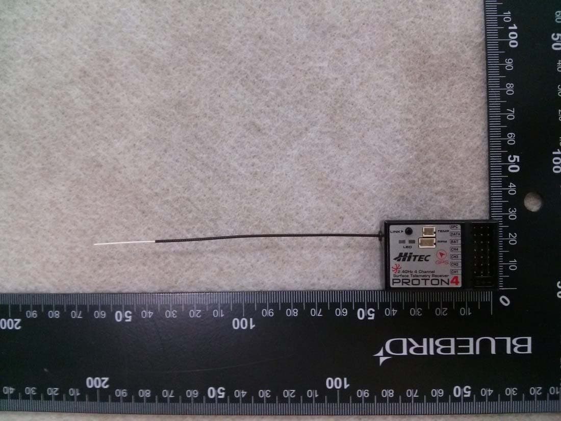
IFHPROTON4
Jul 22, 20142.4GHz Radio Control System
Equipment Class
DSS - Part 15 Spread Spectrum Transmitter