IFHZEBRA472REMOTE CONTROL TRANSMITTER
Hitec RCD Inc.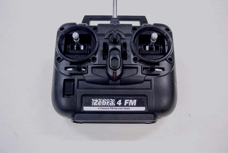
Click to zoom
Application Details
- Equipment Class
- TNB - Licensed Non-Broadcast Station Transmitter
- Date of Grant
- Jul 13, 2006
- Application Purpose
- Original Equipment
- Date of Application
- Jul 13, 2006
- Equipment Note
- REMOTE CONTROL TRANSMITTER
- Frequency Range
- 72.01000000 - 72.99000000
- Company
- Hitec RCD Inc.
- Country
- United States
Documents & Files
Document Text
Text extracted from the exhibit documents filed with the FCC. Open a document above to read the original.
Users Manual
8 Congratulations again and have fun! Austria, Belgium, Denmark, Finland, France, Germany, Greece, Iceland, Ireland, The Netherland, Italy, Spain, Norway, Portugal, United Kingdom, Luxembourg, Sweden, Switzerland Made in the Philippines NEON 4 FM INSTRUCTION MANUAL The following is a listing of replacement parts and accessories available for the Laser radio series from your hobby dealer. A. TX Antenna (#58005) B. Neck strap (#58311) C. Trainer cord (#58310) D. Switch harness (#57215S) E. Heavy duty gold pin switch harness (#54407) F. Stick extensions (#56381) G. Flight Preserver (#58480) 4. Replacement Parts & Accessories - Always turn your transmitter on first and off last. - Never fly your airplane without first performing a proper range check. - FCC regulation in the USA prohibits consumers from changing the crystal in the transmitter. For channel changes send your system to an authorized service/repair center. - Never fly around or over houses, people or power lines. - Always charge your batteries before you fly. - It's a good idea to check your receiver batteries with a tester like the Hitec Power Mate II (part# 44110). This will verify the charge level in your receiver batteries. - Always fly responsibly and respect the rights of others. - Make sure your frequency is clear before turning on your system. 5. Precautions Zebra 4 FM Instruction Manual Instruction Manual 23 1. TRANSMITTER A. Features - Ergonomically designed 4 channel FM transmitter. - High quality precision gimbals with adjustable stick length and tension. - Servo reversing on all channels. - Trainer system. (Slave mode only) - Dry battery pack for six cells for Ni-Mh, Ni-cd, Alkaline battery - Easy to read 1 LED battery indicators. - SIC (Simulator Interface Cable) Compatible Thank you for purchasing the Zebra 4 FM digital proportional radio control system. The Zebra 4 FM is easy to use and utilizes the latest in solid-state components for unsurpassed reliability and performance. It is important that you read and understand this manual before you attempt to operate your system B. Layout System SpecificationsIntroduction Introduction Table of Contents 1. Transmitter a. Features b. Layout c. Specifications d. Servo Reversing e. Control Stick Adjustment f. Stick Lever Tension Adjustment g. Trim Lever h. Reading the LED Battery Indicator 2. Battery Installation 3. Operation a. Installation of Receiver and Servos b. Transmitter, Receiver and Servo Settings c. Trainer System d. Range Checking 4. Replacement Parts & Accessories 5. Precautions Page 2. Page 3. Page 4. Page 5. Page 6. Page 7. Page 8. Table of Contents FRONT Handle Crystal Recharge Jack LED indicator Aileron trim Power switch Elevator trim Aileron/ Elevator stick in MODE II Neck-strap connector Transmitter antenna Throttle/Rudder stick in MODE II Throttle trim Rudder trim Zebra 4 FM Instruction ManualZebra 4 FM Instruction Manual 45 C. Specifications - Power supply : 7.2V (6 cell) Ni-cad/ Ni-Mh battery or 9V 6cell Dry battery - Current drain : 170mA - Output power : 250mw - Modulation : PPM (FM) G. Trim Levers - The trim levers associated with each control stick are used to correct or (trim-out) the tracking of the aircraft. - (Caution) Make sure the trims will move the surface past neutral when moved to their extremes. This will assure you have adequate trim control. - After your plane's first test flight, note the positions of the control surfaces that required trim. Next, center the trims and turn the receiver off. Now adjust the control linkage on the plane so the surfaces are in the same position before the trim levers were re-centered. - Turn on the radio and receiver and recheck the control surfaces to ensure that all the corrections were applied in the proper direction. D. Servo Reversing - The Zebra 4 FM transmitter is equipped with servo reversing on all channels. - If you need to change travel direction of rotation, open the battery case and move the servo reversing switch. E. Control Stick Adjustment - The length of the non-slip control sticks can be adjusted to suit the requirements of the user. F. Stick Lever Tension Adjustment - The unique open-stick assembly provides fully adjustable stick tension to adjust the feel of the sticks in your hands. - You may adjust the stick tension of your sticks to provide the feel that you like for flying. To adjust your springs, you'll have to remove the rear case of the transmitter. Using a screwdriver, remove the six screws that hold the transmitter's rear cover into position, and put them in a safe place. Gently ease off the transmitter's rear cover and move it to the under side of the transmitter, carefully turning it as you would turn the page of a book. Now you'll see the view shown in the illustration. Using a small Philips screwdriver, rotate the adjusting screw for each stick for the desired spring tension. The tension increases when the adjusting screw is turned clockwise, and decreases for counterclockwise motion. When you are satisfied with the spring tensions, you may close the transmitter. Very carefully reinstall the rear cover. When the cover is properly in place, tighten the six screws. AB ZEBRA 4 Stick Lever Tension Zebra 4 FM Instruction ManualZebra 4 FM Instruction Manual BACK Trainer jack Battery jack Servo reversing switch Battery Cover Tension adjusting screw H. Reading the LED Battery Indicator -There is one indicator lights on the face of the radio marked High and Low (blinking). -These relate to the condition of your transmitter battery. Please pay attention to these LED lights and stop flying when the LED light is blinking. 2. BATTERY INSTALLATION - The transmitter requires six and the receiver battery pack needs four AA size batteries. These can be Alkaline, Ni-cad or Ni-Mh cells - When loading the batteries, make sure the receiver and transmitter switches are in the "off" position. - Open the battery door in the back of the transmitter by pressing the tab on the bottom of the battery …
Text truncated - open the document above for the full version.
Users Manual
12115 Paine Street, Poway CA 92064 TEL(858)748-6948 FAX(858)748-1767 WWW.HITECRCD.COM July 11, 2006 TIMCO ENGINEERING INC. TCB & FCB 849 NW State Road 45 FCC Approvals Newberry, Florida 32669 Industry Canada Approvals http://www.timcoengr.com Notified Body for Europe 888.472.2424 F 352.472.2030 email: [email protected] SUBJECT: HITEC RCD INC. - FCC ID: IFHZEBRA472 REFERENCE: JOB 1083AUT6 The following lines will be added or modified to the manuals before product release: - FCC regulation in the USA prohibits changing the crystal in your transmitter. For channel changes send your system to the Manufacturer. The product sent in for testing are pre-production models. The final versions will have the crystals and covers glued in place to prevent users from tampering with them. Sincerely, Tony Ohm Service Manager Hitec RCD, Inc. HITEC RCD USA, INC
Block Diagram
55 44 33 22 11 D D C C B B A A BATTERY SIGNAL TitleSize Document Number Rev Date: Sheet of <Doc> 1 BLOCK DIAGRAM A4 11 Wednesday, March 29, 2006 TitleSize Document Number Rev Date: Sheet of <Doc> 1 BLOCK DIAGRAM A4 11 Wednesday, March 29, 2006 TitleSize Document Number Rev Date: Sheet of <Doc> 1 BLOCK DIAGRAM A4 11 Wednesday, March 29, 2006 OUTPUTFILTER POWERAMPLIFIER DRIVERSTAGE CRYSTALOSCILATORPULSESHIFTER&MODULATOR 5.1VREGULATOR ANTENNA Q32SC2223Y Q42SC2223Y Q52SC4910 ZD15.1V Q1,Q22SC1623YVD1BB535G
Cover Letter(s)
12115 Paine Street, Poway CA 92064 TEL(858)748-6948 FAX(858)748-1767 WWW.HITECRCD.COM 5/11/2006 Federal Communications Commission Authorization and Evaluation Division Confidentiality Request regarding application for certification of FCC ID:IFHZEBRA472 Pursuant to Sections 0.457 and 0.459 of the Commission’s Rules, we hereby request confidential treatment of information accompanying this application as outlined below: Schematics Description of Operation Parts List The above materials contain trade secrets and proprietary information not customarily released to the public. The public disclosure of these materials may be harmful to the applicant and provide unjustified benefits to its competitors. The applicant understands that pursuant to Section 0.457 of the Rules, disclosure of this application and all accompanying documentation will not be made before the date of the Grant for this application. Sincerely, Tony Ohm HITEC RCD USA, INC
External Photos
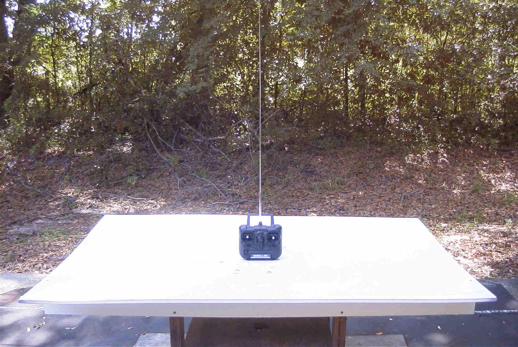
HITEC RCD INC. FCC ID: IFHZEBRA472 EXTERNAL PHOTOS
ID Label/Location Info
FCC ID and IC Sticker: FCC ID: IFHZEBRA472 IC: 3420A-ZEB4FM ZEBRA 4 FM ZEBRA MADE IN THE PHILIPPINES
Internal Photos
HITEC RCD INC. FCC ID: IFHZEBRA472 INTERNAL PHOTOS
Parts List/Tune Up Info
APPLICANT: HITEC RCD INC. FCC ID: IFHZEBRA472 The unit has no provisions for tuning.
Test Report
TIMCO ENGINEERING INC. 849 NW State Road 45 Newberry, Florida 32669 http://www.timcoengr.com 888.472.2424 F 352.472.2030 email: [email protected] APPLICANT: HITEC RCD INC. FCC ID: IFHZEBRA472 REPORT #: H\HITEC\1083AUT6\1083AUT6TestReport.doc COVER SHEET Test Report Product Name: REMOTE CONTROL FCC ID: IFHZEBRA472 Applicant: HITEC RCD INC. 12115 PAINE STREET POWAY CA 92064 Date Receipt: 5/23/2006 Date Tested: 6/27/2006 TIMCO ENGINEERING INC. 849 NW State Road 45 Newberry, Florida 32669 http://www.timcoengr.com 888.472.2424 F 352.472.2030 email: [email protected] APPLICANT: HITEC RCD INC. FCC ID: IFHZEBRA472 REPORT #: H\HITEC\1083AUT6\1083AUT6TestReport.doc TABLE OF CONTENTS TABLE OF CONTENTS LIST TEST REPORT: PAGE 1............GENERAL INFORMATION & TECHNICAL DESCRIPTION PAGE 2............TECHNICAL DESCRIPTION CONTINUED RF POWER OUTPUT PAGE 3............MODULATION CHARACTERISTICS AUDIO FREQUENCY RESPONSE OCCUPIED BANDWIDTH PAGE 4............OCCUPIED BANDWIDTH PLOT PAGE 5............OCCUPIED BANDWIDTH PLOT - CW PAGE 6............FIELD STRENGTH OF SPURIOUS EMISSION PAGE 7............METHOD OF MEASURING RADIATED SPURIOUS EMISSIONS PAGE 8............FREQUENCY STABILITY PAGE 9............TEST EQUIPMENT LIST EXHIBITS INCLUDING: BLOCK DIAGRAM SCHEMATIC PARTS LIST USERS MANUAL LABEL SAMPLE LABEL LOCATION EXTERNAL PHOTOGRAPHS INTERNAL PHOTOGRAPHS ALIGNMENT PROCEDURE OPERATIONAL DESCRIPTION TEST SET UP PHOTOGRAPH TIMCO ENGINEERING INC. 849 NW State Road 45 Newberry, Florida 32669 http://www.timcoengr.com 888.472.2424 F 352.472.2030 email: [email protected] APPLICANT: HITEC RCD INC. FCC ID: IFHZEBRA472 REPORT #: H\HITEC\1083AUT6\1083AUT6TestReport.doc Page 1 of 9 GENERAL INFORMATION 2.1033(c)(1)(2) HITEC RCD INC. will sell the FCC ID: IFHZEBRA472 Radio Control transmitter in quantity, for use under PART 95 SUBPART C. HITEC RCD INC. 12115 PAINE STREET POWAY CA 92064 2.1033(c)(3) Instruction manual is included in the exhibits. 2.1033 (4) Type of Emission: 8K0F1D 95.631 (b)(5) Bn = 2M + 2DK M = 4,800 Bits per second D = 800 Hz (Peak Deviation) K = 1 Bn = 2(4.8/2) + 2(1600)(1) =4.8K + 3.2K =8.0k ALLOWED AUTHORIZED BANDWIDTH = 8.00 kHz. 95.631 (b) Authorized Bandwidth 8 kHz for RC Transmitter 2.1033(c)(6) Frequency Range: 72.01 - 72.99 MHz 95.623 (a)(7) Power Range and Controls: There are NO user Power controls. (8) Function of each electron tube or semiconductor device or other active circuit device are included in the exhibits (9) Maximum Output Power Rating: 0.250 W ERP. (10) DC Voltages and Current into Final Amplifier: FINAL AMPLIFIER ONLY Vce = 7.2 VDC Ice = 0.07 A. Pin = 0.5 W 2.1033(c)(11) Tune-up procedure. The tune-up procedure is included in the exhibits. TIMCO ENGINEERING INC. 849 NW State Road 45 Newberry, Florida 32669 http://www.timcoengr.com 888.472.2424 F 352.472.2030 email: [email protected] APPLICANT: HITEC RCD INC. FCC ID: IFHZEBRA472 REPORT #: H\HITEC\1083AUT6\1083AUT6TestReport.doc Page 2 of 9 2.1033(c)(12) Complete Circuit Diagrams: The circuit diagram are included in the exhibits. (13) Description of all circuitry and devices provided for determining and stabilizing frequency is given in the exhibits. 2.1033(c)(14) The Equipment identification is shown in the exhibits. 2.1033(c)(15) Photographs of the equipment are shown in the exhibits. 2.1033(c)(16) Equipment employing Digital modulation. N/A. 2.1033(c)(17) The data required by 2.1046-2.1057 follows; 2.1046 RF power is measured by the ERP METHOD. There are no provisions to limit the power. With a nominal battery voltage of 7.2 VDC, and the transmitter properly adjusted the RF output measures: Po = 0.250 Watts ERP 2.1046 RF power output. HP SPECTRUM ANALYZER TIMCO ENGINEERING INC. 849 NW State Road 45 Newberry, Florida 32669 http://www.timcoengr.com 888.472.2424 F 352.472.2030 email: [email protected] APPLICANT: HITEC RCD INC. FCC ID: IFHZEBRA472 REPORT #: H\HITEC\1083AUT6\1083AUT6TestReport.doc Page 3 of 9 2.1047 Modulation characteristics: AUDIO FREQUENCY RESPONSE The Voice is NOT allowed in this band. 2.1049 Occupied bandwidth: 95.635 (b) (1) At least 25dB on any frequency removed from the center of the authorized bandwidth by more than 50% up to and including 100% of the authorized bandwidth. (2) At least 45 dB on any frequency removed from the center of the authorized bandwidth by more than 100% up to and including 125% of the authorized bandwidth. (3) At least 55 dB on any frequency removed from the center of the authorized bandwidth by more than 125% up to and including 250% of the authorized bandwidth. (4) At least 56 + 10 log 10 (T) dB on any frequency removed from the center of the authorized bandwidth by more than 250%. Radiotelephone Transmitter with Modulation Limiter Test Procedure Diagram OCCUPIED BANDWIDTH MEASUREMENT TIMCO ENGINEERING INC. 849 NW State Road 45 Newberry, Florida 32669 http://www.timcoengr.com 888.472.2424 F 352.472.2030 email: [email protected] APPLICANT: HITEC RCD INC. FCC ID: IFHZEBRA472 REPORT #: H\HITEC\1083AUT6\1083AUT6TestReport.doc Page 4 of 9 OCCUPIED BANDWIDTH PLOT TIMCO ENGINEERING INC. 849 NW State Road 45 Newberry, Florida 32669 http://www.timcoengr.com 888.472.2424 F 352.472.2030 email: [email protected] APPLICANT: HITEC RCD INC. FCC ID: IFHZEBRA472 REPORT #: H\HITEC\1083AUT6\1083AUT6TestReport.doc Page 5 of 9 2.1051 SPURIOUS EMISSIONS AT ANTENNA TERMINALS NOT APPLICABLE, NO antenna port. This UUT has a permanently attached antenna. 2.1053 UNWANTED RADIATION: 95.635(1)(3)(7)(10)(11)(12) REQUIREMENTS: At least 56 + 10log(T) on any frequency removed from the center of the authorized bandwidth by more than 250%. 56 + 10log(0.250) = 50 dB TEST DATA: Emission Frequency MHz Ant. Polarity dB Below Carrier (dBc) 72.70 145.30V 57.91 218.00V 61.56 290.70V 74.77 363.40V 77.61 436.10V 78.70 508.78H 64.95 581.40V 67.98 654.10H 67.33 726.80H 76.20 TIMCO ENGINEERING INC. 849 NW State Road 45 Newberry, Florida 32669 http://www.timcoengr.com 888.472.2424 F 352.472.2030 email: [email protected] APPLICAN…
Text truncated - open the document above for the full version.
Contact Information
Applicant
Tony Ohm(Service Dept. Manager)
Test Firm
Timco Engineering, Inc.Sid Sanders
Technical Specifications
| # | Rule Parts | Frequency Range | Power Output | Emission | Tolerance |
|---|---|---|---|---|---|
| 1 | 95C | 72.01 MHz - 72.99 MHz | 250.00 mW | 8K0F1D | 20.0000000000 ppm |
Other Applications from Hitec RCD Inc.
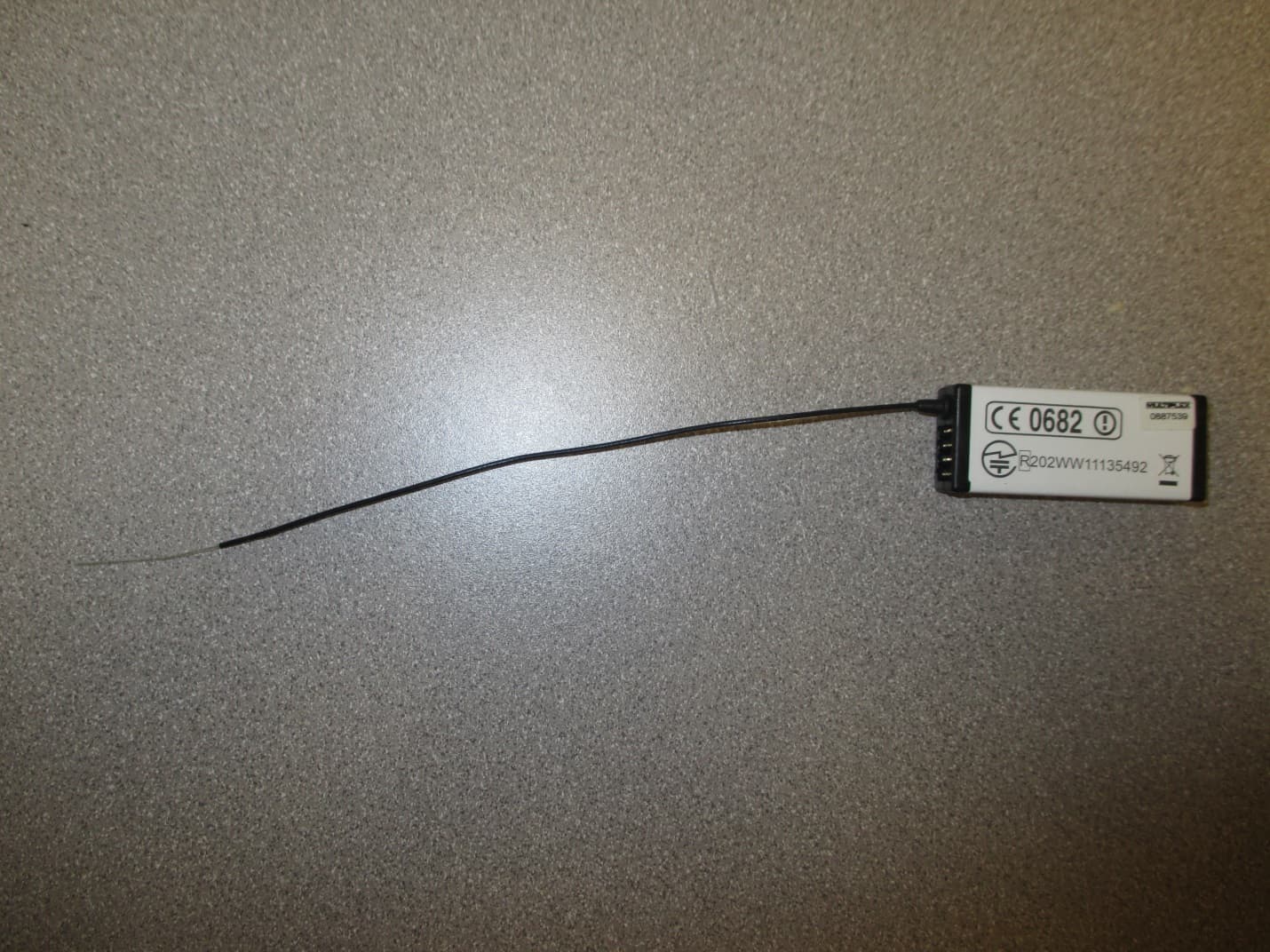
IFHRX57MLINK
Dec 22, 20147 CHANNEL 2.4 GHz TRANSCEIVER
Equipment Class
DSS - Part 15 Spread Spectrum Transmitter
IFHRX5MLINK
Dec 16, 2014RX5 M-LINK CHANNEL 2.4 GHz TRANSCEIVER
Equipment Class
DXX - Part 15 Low Power Communication Device Transmitter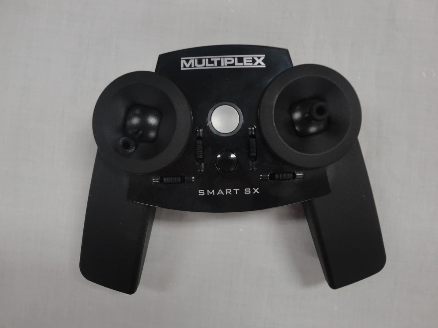
IFHSMART-SX
Sep 16, 20146 CHANNEL 2.4 GHz RADIO CONTROL TRANSMITTER
Equipment Class
DSS - Part 15 Spread Spectrum Transmitter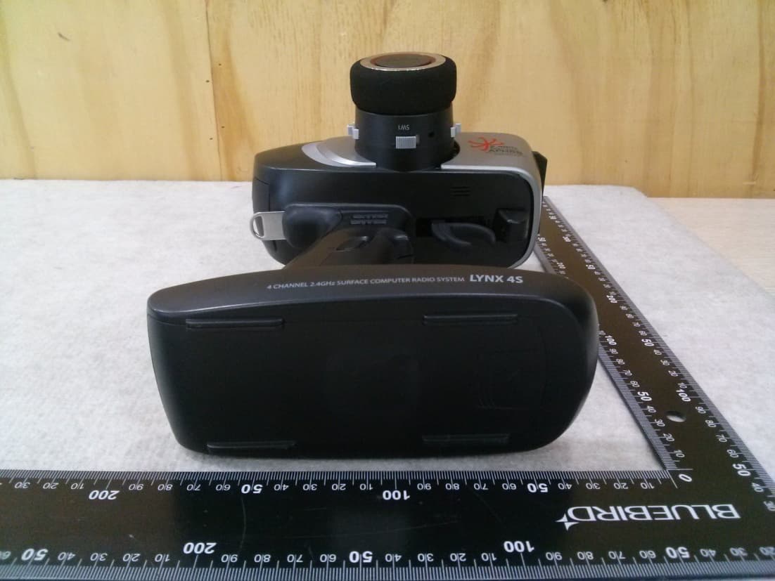
IFHLYNX4S
Jul 22, 20142.4GHz Radio Control System
Equipment Class
DSS - Part 15 Spread Spectrum Transmitter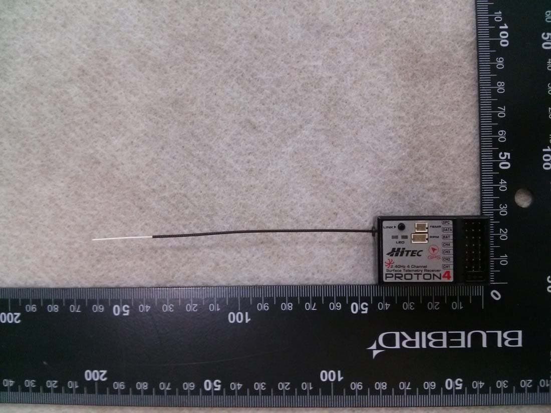
IFHPROTON4
Jul 22, 20142.4GHz Radio Control System
Equipment Class
DSS - Part 15 Spread Spectrum Transmitter