IHET5AP1SC300 800MHz Microcell
Nokia Solutions and Networks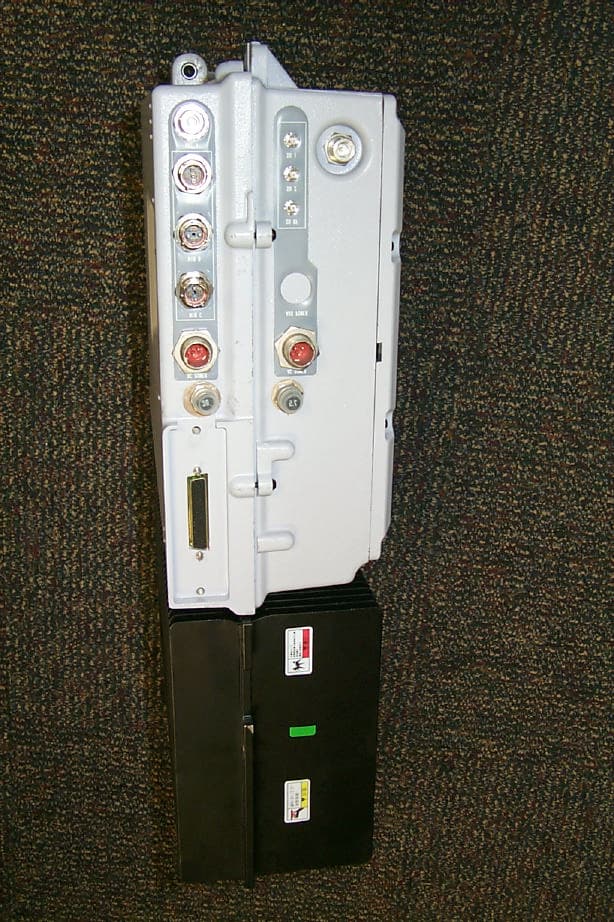
Click to zoom
Application Details
- Equipment Class
- TNB - Licensed Non-Broadcast Station Transmitter
- Date of Grant
- May 31, 2001
- Application Purpose
- Original Equipment
- Date of Application
- Feb 01, 2001
- Equipment Note
- SC300 800MHz Microcell
- Frequency Range
- 869.70000000 - 893.31000000
- Company
- Nokia Solutions and Networks
- Country
- United States
Documents & Files
Document Text
Text extracted from the exhibit documents filed with the FCC. Open a document above to read the original.
Users Manual
SCt300 BTS Hardware Installation, ATP and FRU Procedures Software Release 2.15.x.x SCt300 CDMA English DEC 2000 68P09224A55–1 PRELIMINARY PRELIMINARY Notice While reasonable efforts have been made to assure the accuracy of this document, Motorola, Inc. assumes no liability resulting from any inaccuracies or omissions in this document, or from use of the information obtained herein. The information in this document has been carefully checked and is believed to be entirely reliable. However, no responsibility is assumed for inaccuracies or omissions. Motorola, Inc. reserves the right to make changes to any products described herein and reserves the right to revise this document and to make changes from time to time in content hereof with no obligation to notify any person of revisions or changes. Motorola, Inc. does not assume any liability arising out of the application or use of any product, software, or circuit described herein; neither does it convey license under its patent rights or the rights of others. It is possible that this publication may contain references to, or information about Motorola products (machines and programs), programming, or services that are not announced in your country. Such references or information must not be construed to mean that Motorola intends to announce such Motorola products, programming, or services in your country. Copyrights This instruction manual, and the Motorola products described in this instruction manual may be, include or describe copyrighted Motorola material, such as computer programs stored in semiconductor memories or other media. Laws in the United States and other countries preserve for Motorola certain exclusive rights for copyrighted material, including the exclusive right to copy, reproduce in any form, distribute and make derivative works of the copyrighted material. Accordingly, any copyrighted Motorola material contained herein or in the Motorola products described in this instruction manual may not be copied, reproduced, distributed, merged or modified in any manner without the express written permission of Motorola. Furthermore, the purchase of Motorola products shall not be deemed to grant either directly or by implication, estoppel, or otherwise, any license under the copyrights, patents or patent applications of Motorola, as arises by operation of law in the sale of a product. Usage and Disclosure Restrictions License Agreement The software described in this document is the property of Motorola, Inc. It is furnished by express license agreement only and may be used only in accordance with the terms of such an agreement. Copyrighted Materials Software and documentation are copyrighted materials. Making unauthorized copies is prohibited by law. No part of the software or documentation may be reproduced, transmitted, transcribed, stored in a retrieval system, or translated into any language or computer language, in any form or by any means, without prior written permission of Motorola, Inc. High Risk Activities Components, units, or third–party products used in the product described herein are NOT fault–tolerant and are NOT designed, manufactured, or intended for use as on–line control equipment in the following hazardous environments requiring fail–safe controls: the operation of Nuclear Facilities, Aircraft Navigation or Aircraft Communication Systems, Air Traffic Control, Life Support, or Weapons Systems (“High Risk Activities”). Motorola and its supplier(s) specifically disclaim any expressed or implied warranty of fitness for such High Risk Activities. Trademarks and Motorola are registered trademarks of Motorola, Inc. Product and service names profiled herein are trademarks of Motorola, Inc. Other manufacturers’ products or services profiled herein may be referred to by trademarks of their respective companies. Copyright Copyright 2000 Motorola, Inc. All Rights Reserved Printed on Recyclable Paper REV010600 SPECIFICATIONS SUBJECT TO CHANGE WITHOUT NOTICE DEC 2000 i SCt300 BTS Hardware Installation, ATP and FRU Procedures PRELIMINARY Table of Contents SCt300 BTS Hardware Installation, ATP and FRU Procedures Software Release 2.15.x.x List of Figuresv. . . . . . . . . . . . . . . . . . . . . . . . . . . . . . . . . . . . . . . . . . . . . . . . . . . List of Tablesxi. . . . . . . . . . . . . . . . . . . . . . . . . . . . . . . . . . . . . . . . . . . . . . . . . . . Forewordxvii. . . . . . . . . . . . . . . . . . . . . . . . . . . . . . . . . . . . . . . . . . . . . . . . . . . . . . . General Safetyxx. . . . . . . . . . . . . . . . . . . . . . . . . . . . . . . . . . . . . . . . . . . . . . . . . . . Revision Historyxxii. . . . . . . . . . . . . . . . . . . . . . . . . . . . . . . . . . . . . . . . . . . . . . . . . Patent Notificationxxiii. . . . . . . . . . . . . . . . . . . . . . . . . . . . . . . . . . . . . . . . . . . . . . . Chapter 1: Introduction Introduction1-1. . . . . . . . . . . . . . . . . . . . . . . . . . . . . . . . . . . . . . . . . . . . . . . . . . . . . Required Documents1-11. . . . . . . . . . . . . . . . . . . . . . . . . . . . . . . . . . . . . . . . . . . . . . Installation Tools and Materials1-12. . . . . . . . . . . . . . . . . . . . . . . . . . . . . . . . . . . . . ATP Tools and Materials1-16. . . . . . . . . . . . . . . . . . . . . . . . . . . . . . . . . . . . . . . . . . FRU Tools and Materials1-21. . . . . . . . . . . . . . . . . . . . . . . . . . . . . . . . . . . . . . . . . . Unit Identification1-22. . . . . . . . . . . . . . . . . . . . . . . . . . . . . . . . . . . . . . . . . . . . . . . . Installation and ATP Order1-32. . . . . . . . . . . . . . . . . . . . . . . . . . . . . . . . . . . . . . . . . Chapter 2: Site Preparation Site Preparation Overview2-1. . . . . . . . . . . . . . . . . . . . . . . . . . . . . . . . . . . . . . . . . Site Inspections2-2. . . . . . . . . . . . . . . . . . . . . . . . . . . . . . . . . . . . . . . . . . . . . . . . . . Prepare Site for the Arrival …
Text truncated - open the document above for the full version.
Users Manual
DEC 2000 SCt300 BTS Hardware Installation, ATP and FRU Procedures PRELIMINARY Chapter 6: Installing the Unit and Installation Check Off List Table of Contents Unit Installation Overview6-1. . . . . . . . . . . . . . . . . . . . . . . . . . . . . . . . . . . . . . . . . Overview6-1. . . . . . . . . . . . . . . . . . . . . . . . . . . . . . . . . . . . . . . . . . . . . . . . Unit Installation Procedure Order6-1. . . . . . . . . . . . . . . . . . . . . . . . . . . . . Connector Locations6-2. . . . . . . . . . . . . . . . . . . . . . . . . . . . . . . . . . . . . . . . . . . . . . Connector Locations6-2. . . . . . . . . . . . . . . . . . . . . . . . . . . . . . . . . . . . . . . Attaching Back Fin Cover to Unit6-5. . . . . . . . . . . . . . . . . . . . . . . . . . . . . . . . . . . Objective6-5. . . . . . . . . . . . . . . . . . . . . . . . . . . . . . . . . . . . . . . . . . . . . . . . When to Use the Fin Covers6-5. . . . . . . . . . . . . . . . . . . . . . . . . . . . . . . . . Procedure6-5. . . . . . . . . . . . . . . . . . . . . . . . . . . . . . . . . . . . . . . . . . . . . . . . Attaching Optional Installation Handles to the Unit6-6. . . . . . . . . . . . . . . . . . . . . Objective6-6. . . . . . . . . . . . . . . . . . . . . . . . . . . . . . . . . . . . . . . . . . . . . . . . Required Tools and Materials6-6. . . . . . . . . . . . . . . . . . . . . . . . . . . . . . . . Procedure to Attach the Installation Handles to the Unit6-6. . . . . . . . . . . Attaching Unit to Mounting Bracket6-8. . . . . . . . . . . . . . . . . . . . . . . . . . . . . . . . . Objective6-8. . . . . . . . . . . . . . . . . . . . . . . . . . . . . . . . . . . . . . . . . . . . . . . . Background6-8. . . . . . . . . . . . . . . . . . . . . . . . . . . . . . . . . . . . . . . . . . . . . . Tools and Materials6-8. . . . . . . . . . . . . . . . . . . . . . . . . . . . . . . . . . . . . . . . Procedure to Attach the Unit to the Mounting Bracket6-9. . . . . . . . . . . . . Earth Ground Cabling6-11. . . . . . . . . . . . . . . . . . . . . . . . . . . . . . . . . . . . . . . . . . . . . Objective6-11. . . . . . . . . . . . . . . . . . . . . . . . . . . . . . . . . . . . . . . . . . . . . . . . Other Grounding Considerations6-11. . . . . . . . . . . . . . . . . . . . . . . . . . . . . . Cable Description6-11. . . . . . . . . . . . . . . . . . . . . . . . . . . . . . . . . . . . . . . . . Tools and Materials6-11. . . . . . . . . . . . . . . . . . . . . . . . . . . . . . . . . . . . . . . . Attaching Front Fin Cover to Unit6-14. . . . . . . . . . . . . . . . . . . . . . . . . . . . . . . . . . . Objective6-14. . . . . . . . . . . . . . . . . . . . . . . . . . . . . . . . . . . . . . . . . . . . . . . . When to Use the Fin Covers6-14. . . . . . . . . . . . . . . . . . . . . . . . . . . . . . . . . Procedure6-14. . . . . . . . . . . . . . . . . . . . . . . . . . . . . . . . . . . . . . . . . . . . . . . . Attaching the Site I/O Junction Box to the Unit6-15. . . . . . . . . . . . . . . . . . . . . . . . Objective6-15. . . . . . . . . . . . . . . . . . . . . . . . . . . . . . . . . . . . . . . . . . . . . . . . Required Tools and Materials6-15. . . . . . . . . . . . . . . . . . . . . . . . . . . . . . . . Procedure to Attach the Site I/O Junction Box to the Unit6-15. . . . . . . . . . Procedure to Attach a Site I/O Cap to the Unit (optional)6-16. . . . . . . . . . 6 Table of Contents – continued PRELIMINARY SCt300 BTS Hardware Installation, ATP and FRU Procedures DEC 2000 Attaching the Short Duration Battery to the Unit (optional)6-17. . . . . . . . . . . . . . . Objective6-17. . . . . . . . . . . . . . . . . . . . . . . . . . . . . . . . . . . . . . . . . . . . . . . . Required Tools and Materials6-17. . . . . . . . . . . . . . . . . . . . . . . . . . . . . . . . Procedure to Attach the Battery to the Unit6-17. . . . . . . . . . . . . . . . . . . . . Short Duration Battery Cabling6-19. . . . . . . . . . . . . . . . . . . . . . . . . . . . . . . . . . . . . Objective6-19. . . . . . . . . . . . . . . . . . . . . . . . . . . . . . . . . . . . . . . . . . . . . . . . Battery Cable6-19. . . . . . . . . . . . . . . . . . . . . . . . . . . . . . . . . . . . . . . . . . . . . Procedure6-19. . . . . . . . . . . . . . . . . . . . . . . . . . . . . . . . . . . . . . . . . . . . . . . . AC Power Cabling6-21. . . . . . . . . . . . . . . . . . . . . . . . . . . . . . . . . . . . . . . . . . . . . . . Objective6-21. . . . . . . . . . . . . . . . . . . . . . . . . . . . . . . . . . . . . . . . . . . . . . . . Cable Description6-21. . . . . . . . . . . . . . . . . . . . . . . . . . . . . . . . . . . . . . . . . Power Cable and Connector Signal Information6-21. . . . . . . . . . . . . . . . . . Procedure6-21. . . . . . . . . . . . . . . . . . . . . . . . . . . . . . . . . . . . . . . . . . . . . . . . DC Power Cabling6-23. . . . . . . . . . . . . . . . . . . . . . . . . . . . . . . . . . . . . . . . . . . . . . . Objective6-23. . . . . . . . . . . . . . . . . . . . . . . . . . . . . . . . . . . . . . . . . . . . . . . . Cable Decription6-23. . . . . . . . . . . . . . . . . . . . . . . . . . . . . . . . . . . . . . . . . . Power Cable and Connector Signal Information6-23. . . . . . . . . . . . . . . . . . Procedure6-23. . . . . . . . . . . . . . . . . . . . . . . . . . . . . . . . . . . . . . . . . . . . . . . . Antenna Cabling for Sites Equipped With Customer–Supplied Site I/O Interface6-25. . . . . . . . . . . . . . . . . . . . . . . . . . . . . . . . Objective6-25. . . . . . . . . . . . . . . . . . . . . . . . . . . . . . . . . . . . . . . . . . . . . . . . Cable Labels6-25. . . . . . . . . . . . . . . . . . . . . . . . . . . . . . . . . . . . . . . . . . . . . Cable Descriptions6-25. . . . . . . . . . . . . . . . . . . . . . . . . . . . . . . . . . . . . . . . . Procedure6-25. . . . . . . . . . . . . . . . . . . . . . . . . . . . . . . . . . . . . . . . . . . . . . . . Antenna Cabling for Sites Equipped with Optional Primary Surge Suppre…
Text truncated - open the document above for the full version.
Attestation Statements
_________________________________________________________________________________________________________ FCC Filing - SC300 @ 800 MHz CDMA BTS Frame Network Systems Group CDMA Systems Division FCC ID: IHET5AP1 STATEMENTS OF CERTIFICATION EXHIBIT
Block Diagram
Block diagram of SC300 800 MHz BTS FCC ID IHET5AP1
Cover Letter(s)
Cellular Infrastructure Group January 16, 2001 Federal Communications Commission Authorization & Evaluation Division 7435 Oakland Mills Road Columbia, Maryland 21046 Re: Application for Cellular Transceiver Certification Gentlemen: Motorola Inc., 1475 W. Shure Drive, Arlington Heights, Illinois 60004, herein submits: Filing fee , Application for Equipment Authorization (FCC Form 731) and Sections, for Certification of a PCS Cellular Transceiver, FCC ID: IHET5AP1. Motorola is also the manufacturer of this equipment. Motorola requests that the following Sections of the Schematics Exhibit be kept confidential: Section A NIU – Network Interface Unit Section BCEM – Channel Element Module Section CRFCC – Radio Frequency Control Card Section DILPA – Power Amplifier Section E DC/DC Converter Board The confidential portions have been identified as such on the Uploading Sections Form. The filing fee includes $145.00, the amount for a confidential filing. Page 1 of 2
External Photos
Cellular Infrastructure Group APPLICANT: MOTOROLA TRANSCEIVER TYPE: IHET5AP1 SC300 @ 800 MHz CDMA BTS EXTERNAL PHOTOS EXHIBIT List of External Photographs No. PHOTOGRAPH 1 Front View 2 RearView 3 Right Side View 4 Left Side View 5 Top View
ID Label/Location Info
1 Location of FCC ID Label SC300 @ 800 MHZ CDMA BTS IHET5AP1
Internal Photos
Cellular Infrastructure Group APPLICANT: MOTOROLATRANSCEIVER TYPE: IHET6AP1 SC4812ETL @ 1.9 GHz CDMA BTS INTERNAL PHOTOS EXHIBIT No. PHOTOGRAPH
Operational Description
FCC Filing- SC300 @800 MHz CDMA BTS1 DESCRIPTIVE INFORMATION FCC FILING FOR SC300 @ 880 MHz CDMA BTS The Information in this exhibit is in accordance with the FCC Rules and Regulations, Vol. II, Part 2, Subpart J. Sections 2.983 through 2.999 are addressed. Section 2.983 (a)Name of Applicant and Manufacturer: MOTOROLA Section 2.983 (b) Identification of Equipment: IHET5AP1 Section 2.983 (c) Quantity Production: Quantity Production is Planned. Section 2.983 (d) Technical Description This Transmitter is intended for use in the Public Cellular Radio Telecommunications Service and is designed in compliance with the FCC Rules and Regulations Title 47, Part 22. This transmitter is capable of spread spectrum (CDMA) operation, and allows up to 32 Walsh codes to support Pilot, Sync, Paging and Traffic channels. (1) Types of Emissions This equipment will be capable of operation using wide band spread spectrum techniques employing Direct Sequence Code Division Multiple Access (DS- CDMA) digital communication techniques. For this transmitter, the emission designator is 1M25F9W (per FCC Part 2.201, subpart C). (2)Frequency RangeThis transmitter operates within the 869.70 to 893.31 MHz Band (per FCC Part 22). This base station will support CDMA operations on channel numbers 1013 through 1023 and 1 through 777 inclusive. 3) Range of Operating Power The rated maximum average power out of the SC300 @880 MHz CDMA BTS is 10 W (40.0 dBm). However, in CDMA the actual power output is based on the number of traffic channels in operation. The minimum power occurs when only a pilot signal is present. The maximum power occurs when a pilot along with synchronization, paging, and traffic channels are present. For a typical system setup, the theoretical difference between minimum power and maximum power is 8dB. The output power is variable in 0.25 dB steps. The range is 12 dB. FCC Filing- SC300 @800 MHz CDMA BTS2 (3) Range of Operating Power (cont.) In addition, the dynamics of a CDMA system allow for what is called “cell breathing”. This allows an operator to vary the range of a cell by controlling the power of the pilot signal. (4) Maximum Power Limits The peak output power of a base station transmitter may not exceed 500 Watts as defined in Part 22.913 (a). (5)Applied voltages and currents into the final transistor elements of the transmitter output: In the CDMA system, the applied voltages and currents into the final transistor elements SRF7042X2 for 10 W output: Drain 27.7 VDC Drain Current 1.0 AMPS x 2 Gate Voltage 4 VDC (6) Function of Each Active Device Refer to the Operational Description Exhibit. (7) Complete Circuit Diagrams Refer to the Schematics Exhibit. (8) Instruction/Installation Manual Refer to the Installation Manual Exhibit. (9) Tune-Up/Optimization Procedure Refer to the Users Manual Exhibit. FCC Filing- SC300 @800 MHz CDMA BTS3 (10) Means for Frequency Stabilization Refer to Section F of the Test Report Exhibit. The GPS/HSO Module provides clock and time signals for an SC300 @880 MHz CDMA BTS. In addition, it provides the primary source, a 3 MHz clock, for the transmit synthesizer in the RFCC Transceiver. The module relies on a GPS receiver, remotely located in an integrated package with the GPS antenna as the primary time reference for the ovenized oscillator. Redundancy is also provided a High Stability Oscillator (HSO) The HSO is provided in case of GPS system failure. The GPS Module uses the received signals as a reference to provide the required clock for the site. The module distributes CDMA time, a 19.6608 MHz clock, and a two-second synchronization pulse every even second of universal time to the RFCC. (11) Means for Attenuation of Spurious Emissions Refer to Section C of the Test Report Exhibit. Bandpass filters are employed in the transmit RF circuit to attenuate far out spurious emissions. The filter used here is of an air dielectric cavity resonator type. The baseband employs a discrete L-C 7-pole elliptic filter. This filter is used to attenuate sideband noise and close in spurious emissions. In addition, suppression of spurious radiation is obtained by proper shielding techniques. Means for Limiting Modulation Refer to Sections B and F of the Test Report Exhibit. In a CDMA system, the input signal (voice for example) is sampled and coded in a vocoder. This signal is then spread to 1.23 MHz by a pseudo-random spreading code. This spreading code sets the bandwidth of the spread-spectrum signal. If more than one signal is in operation (i.e. more than one voice channel), then the two signals are simply layered one atop the other within the 1.23 MHz band. So, to some extent, the bandwidth of the transmitted signal is limited by the chip rate of the PN spreading code. FCC Filing- SC300 @800 MHz CDMA BTS4 Primary limiting of the CDMA signal bandwidth is accomplished by the use of a programmable digital limiter and Finite Impulse Response (FIR) filters in the RFCC. The digital limiter prevents occasional large peaks and thus avoids wrap- around error that would occur. The FIR filters are 13 Tap and run with four sets of coefficients at a 4X rate, thus being equivalent to a 48-tap linear FIR filter. Output I and Q data streams from the filters are guaranteed to be 45 dBc below the carrier at 750 kHz offset. Further filtering of the analog wave is accomplished through the use of a 7-pole elliptic filter in the RFCC. A more detailed description of the FIR filter response is given in the following graph. The baseband filters have a linear phase. In addition, they have a frequency response S(f) that satisfies the limits shown in the figure below. The normalized frequency response of the filter shall be contained within plus or minus error (e1) in the passband and shall be less than or equal to error (e2) in the stop band (f>fs). The numerical values for the parameters are e1=1.5dB, e2=-40dB, fp=590kHz, and fs=740kHz. 20 (log|S(f)|) base 10 e1 e1 e2 0 fpfs0f BA SEBA ND FILTER S F REQU ENC Y R E…
Text truncated - open the document above for the full version.
Parts List/Tune Up Info
Summary of Active DevicesSC300 800MHz Applicant: MotorolaIHET5AP1 Radio Frequency Control Card- RFCC Device Type #Component DescriptionOperating Frequency 74ABT125DIC BICMOS 74AB19.6608MHz VXML14EVCXO 32.768MHZ32.768MHz 970-2178-29OCXO 19.6608MH19.6608MHz BRPG1204W-TRLED BI COLOR RDC MMBT3904TSTR NPN 40V . Voltage follower for VCXO_ADJDC XSTR PNP40V .2XSTR PNP40V .2DC HSM633 40 MHzOSC 40MHZ CONN40 MHz AD826ARDual high speed op amp1.288 MHz 3 MHz AT259VOLTAGE CONTROLDC GT28F320B3BA110 IC 32 MBIT Flash memory word wide 2048x1640 MHz max X03D75810-960 MHzIC CDMA EXCITE810-960 MHz RF2422IC MODUL QUADR810-960 MHz AD9850BRSIC 125MHZ DDS3 MHz/19.6608 MHz MAX3223EADIC XCVR RS23210 KHz IDT74FCT163344CPAIC ADR/CLK DRV40 MHz max L2A0959IC ASIC EDTC19.6608MHz/40 MHz IDT49FCT3805APYIC BFFR/CLK DR40 MHz 19.6608MHz XC4020XL-3BG256-1IC FPGA 20K GA19.6608MHz/40 MHz CY7C1021v32-15BAIIC SRAM 64KX1616.384 MHz MAX487ESAIC RS485 Trasceiver1 Hz 10 kHz MAX5250BEAPIC DAC QUAD 10-BIT SERIAL1 MHz max MAX148BEAPIC ADC 8 Channel 10-Bit Serial1 MHz max DS92LV010IC LVDS Transceiver16.384 MHz 8 kHz 0.5 Hz 2.048 MHz IC CENT TE,P S800 MHz IC DUAL PRECIS800 MHz IC CONV VOLTAG800 MHz UPC2776TIC MMIC IS Amplifier800 MHz MSM13R2850-073LSIC ASIC DBP 256 BGA200 MHz REF 192FSIC REF VOLTAGEDC LMC7101A1M5XIC OP AMP LMC720 MHz RI25033IC Low Noise Down Converter20 MHz XPC860MHCZP50C1IC POWER QUICC40 MHz 74ACT244IC OCT LINE DRDC IC DIFF PECL T800 MHz IC 1:2 DIFF FA MC10ELT26IC 1:2 FANOUT20 MHz MC145151-2IC PLL FREQ SY800 MHz MC33269DT-5.0IC LDO Voltage Regulator40 MHz LP2951IC LDO Voltage Regulator19.6608 MHz IC LOW PWR J F8 kHz; 1 kHz IC NAND QUAD 2800 MHz IC OR QUAD 2 I800 MHz IC LINE DRVR O800 MHz IC BUFFER 16 BDC Motorola/MC74LCX157IC MUX QUAD 2-DC;40 MHz Motorola/MC74LCX16374IC 16 BIT D/FL40 MHz Dallas/DS1706IC MICRO MONITDC Analog Devices/AD9762ARIC 12 BIT DIG1.288 MHz Analog Devices/AD6600ASTIC AD6600AST 219.6608 MHz NEC/UPC-2708AMPL BIPOLAR M238.4 MHz Analog Devices/TMP-01IC TEMP. SENSOR/CONTROLLERDC Motorola/SY38157BT05RZ Power QUICC Peripheral Control PPC ASIC40 MHz NEC/UPC-2776TIC MMIC SI AMP238.4 MHz NEC/UPC-2776TIC MMIC SI AMP238.4 MHz LT1529IQIC LDO Voltage RegulatorDC M/A-Com/ AM50-0003IC AMPLIFIER L800 - 1000 MHz M/A-Com/ AT259Voltage Controlled AttenuatorDC National Semiconductor/LM50CIM3X Temp. sensor ICDC Linear Technology/LT1054IS8Voltage Converter ICDC NEC/UP2776RF Gain block200 - 900 MHz NEC/UP2708RF Gain block200 - 900 MHz OKIDBP ASIC238 MHz National Semiconductor/LMC7101Low Power OP AMP200 - 900 MHz Conexant/RI 25033Low Noise Mixer200 - 900 MHz Motorola/ MC79M05BDTBipolar RegulatorDC Motorola/MC10ELT21Differential PECL/TTL TranslatorDC Motorola/MC10EL111:2 Differential BufferDC Motorola/MC33161Voltage Monitor ICDC Motorola/MC332695V Voltage RegulatorDC National Semiconductor/LP29513.3V voltage regulatorDC Analog Devices / AD6600A/D Converter19.6608 MHz(sampling) M/A-COM /MLS9061-50598Synthesizer583 - 613 MHz M/A-COM /MLS9132-50882Synthesizer869 - 894 MHz National / LM29805V RegulatorDC Motorola SPS/ X03D75810-960Exciter BGA810 - 960 MHz RF Micro Devices/ RF2422Quadrature Modulator2.5 GHz M/A-Com/ AM50-0003Low Noise Amplifier800 - 1000 MHz Burr-Brown/ OPA2234UOperational Amplifiers- Analog Devices/ AD603AR-R7voltage-controlled amplifier 9-90 MHz Network Interface Unit - NIU Device Type #Component DescriptionOperating Frequency MMBT3904TSTR NPN 40V .DC MOC205IC OPTO-ISOLATDC MC74LCX04IC INVERT HEX8 KHz 20 MHz MC74LCX08IC AND QUAD 210 MHz max MC74LCX244IC LINE DRVR ODC MC74LCX245IC 8BIT NON-IN10 MHz max LXT907PC10 BASE ETHERNET PHY20 MHz XE1414MASSY MODEM MDL28.4 MHz PEB2256IC E1/T1 /J1 F20 MHz HG-1012JA-20MBX2OSC HI STABILI20 MHz DC/DC Converter Device Type #Component DescriptionOperating Frequency Lucent/ JC100C1POWER MODULE 15V (100W)500KHz Lucent/ JC050A1POWER MODULE 5V (50W)500KHz Lucent/ JC050F1POWER MODULE 3.3V (50W)500KHz Lucent/ FC250R1POWER MODULE 28V (250W)500KHz LM2941T flow LB04Adj. Low Dropout VRegDC Power Trends/PT6653MIntegrated Switching Reg 5V 5A550KHz Motorola/ MJD243T4TRANSISTOR 100V 4ADC Analog Devices/TMP01Temperature SensorDC Motorola/MMBT3904LT1NPN Transistor 40VDC Motorola/MMBT5550LT1NPN Transistor 140VDC Channel Elements Module - CEM Manufacturer#DescriptionOperating Frequency SY38157JZ02AIC ASIC EMAXII-17X1719.6608 MHz SCM6341ZP12AIC SRAM 128KX2440 MHz max MC74LCX02IC NOR QUAD 240 MHz max MC74LCX08IC AND QUAD 240 MHz max 74LVCH32501AIC REGISTER 3640 MHz max XC56311GC150IC 24BIT DSP 140 MHz / 150 MHz MIC5207-2.5BM5REG MIC5207-1.DC IC BFFR/CLK DR19.6608 MHz Integrated Linear Power Amplifier - ILPA Device Type #Component Description Operatin g Frequency MRF284S TSTR LDMOS RF 26V 30W 1500MHZ869MHz thru 894MHz SRF7042R2 TSTR RF POWER 80W 869MHz thru 894MHz QBH-8944 IC AMP BDBD HI GAIN 50OHM SO10869MHz thru 894MHz MSA-1105 MMIC GAIN BLOCK GRADED869MHz thru 894MHz PST-H9627 IC GAIN BLOCK SMT INA10386869MHz thru 894MHz
RF Exposure Info
FCC Requirements PRELIMINARY SCt300 BTS Hardware Installation, ATP and FRU Procedures MAY 2001 xx Content This section presents Federal Communications Commission (FCC) Rules Parts 15 and 68 requirements and compliance information for the SCt300 Microcell Base Transceiver Stations (BTS). Warning – Radio Frequency Radiation Hazard This equipment is designed to generate and radiate radio frequency (RF) energy. It should be installed and maintained only by trained technicians. Licensees of the Federal Communications Commission (FCC) using this equipment are responsible for insuring that its installation and operation comply with FCC regulations (47 C.F.R. & 1.1310) designed to limit human exposure to RF radiation. WARNING MPE Limit Warning In order to comply with the FCC guidelines on RF exposure, the antennas for this equipment must not exceed the maximum gain shown in the MPE Limits table. Antennas must be installed more than the minimum distance specified in the MPE Limits table away from persons. No antenna used with this equipment should be installed in a location in which any persons are likely to be within the maximum persmissable distance from the antenna. Verify that transmitter output is turned off before performing antenna service within the restricted area. WARNING MPE Limits ParameterFrequency 800 MHz1.9 GHz Maximum Gain5.2dBd5.5dBi Distance1.0m (40 in.)0.5m (20 in.) FCC Requirements – continued MAY 2001 xxi SCt300 BTS Hardware Installation, ATP and FRU Procedures PRELIMINARY FCC Part 15 Requirements Part 15.19a(3) – Information to User This device complies with Part 15 of the FCC Rules. Operation is subject to the following two conditions: (1) This device may not cause harmful interference, and (2) this device must accept any interference received, including interference that may cause undesired operation. Part 15.21 – Information to User Changes or modifications not expressly approved by Motorola could void your authority to operate the equipment. Part 15.105(b) – Information to User This equipment has been tested and found to comply with the limits for a Class B digital device, pursuant to Part 15 of the FCC Rules. These limits are designed to provide reasonable protection against harmful interference in a residential installation. This equipment generates, uses and can radiate radio frequency energy and, if not installed and used in accordance with the instructions, may cause harmful interference to radio communications. However, there is no guarantee that interference will not occur in a particular installation. If this equipment does cause harmful interference to radio or television reception, which can be determined by turning the equipment OFF and ON, the user is encouraged to try to correct the interference by one or more of the following measures: SReorient or relocate the receiving antenna. SIncrease the separation between the equipment and receiver. SConnect the equipment into an outlet on a circuit different from that to which the receiver is connected. SConsult the dealer or an experienced radio/TV technician for help. FCC Part 68 Requirements This equipment complies with Part 68 of the Federal Communications Commission (FCC) Rules. A label located on the upper–right corner of the right side of the cooling fins contains, among other information, the FCC Registration Number and Ringer Equivalence Number (REN) for this equipment. If requested, this information must be provided to the telephone company. The REN is useful to determine the quantity of the devices which may connect to the telephone line. Excessive RENs on the telephone line may result in the devices not ringing in response to incoming calls. In most, but not all areas, the sum of the RENs should not exceed five (5.0). To be certain of the number of devices that may be connected to the line as determined by the total RENs, contact the telephone company to determine the maximum REN for the calling area. If the dial–in site access modem causes harm to the telephone network, the telephone company will notify you in advance that temporary FCC Requirements – continued PRELIMINARY SCt300 BTS Hardware Installation, ATP and FRU Procedures MAY 2001 xxii discontinuance of service may be required. If advance notice is not practical, the telephone company will notify you of the discontinuance as soon as possible. Also, you will be advised of your right to file a complaint with the FCC if you believe it is necessary. The telephone company may make changes in its facilities, equipment, operations, or procedures that could affect the operation of your dial–in site access modem. If this happens, the telephone company will provide advance notice so that you can modify your equipment as required to maintain uninterrupted service. If you experience trouble with the dial–in site access modem, please contact: Motorola Customer Network Resolution Center (CNRC) 3436 N. Kennicot Drive Arlington Heights, Illinois 60004 Phone Number: 800–433–5202 for repair and/or warranty information. If the trouble is causing harm to the telephone network, the telephone company may request you to disconnect the equipment from the network until the problem is solved. You should not attempt to repair this equipment yourself. This equipment contains no customer or user–serviceable parts. Changes or modifications not expressly approved by Motorola c…
Text truncated - open the document above for the full version.
Contact Information
Applicant
Steve Mitchell
Technical Contact
MotorolaBrian Costello
[email protected]847-632-5060
1475 W Shure Dr, IL75, room F520 · Arlington Heights, Illinois · United States
Non-Technical Contact
MotorolaZoran Husner
[email protected]847-632-7769
Technical Specifications
| # | Rule Parts | Frequency Range | Power Output | Emission | Tolerance |
|---|---|---|---|---|---|
| 1 | 22.901(d) | 869.7 MHz - 893.31 MHz | 10 W | 1M25F9W | 1.5000000000 ppm |
Other Applications from Nokia Solutions and Networks
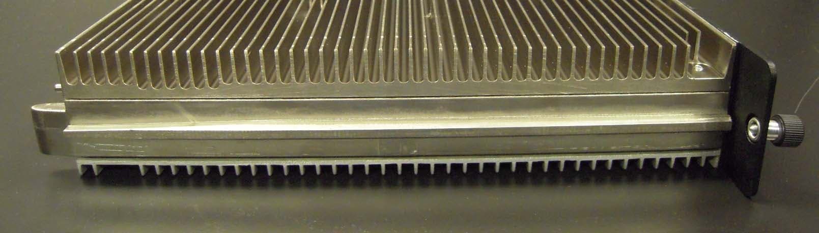
IHET4KJ1
Apr 28, 2010LTE 700 MHz Public Safety Base Station Transceiver
Equipment Class
TNB - Licensed Non-Broadcast Station Transmitter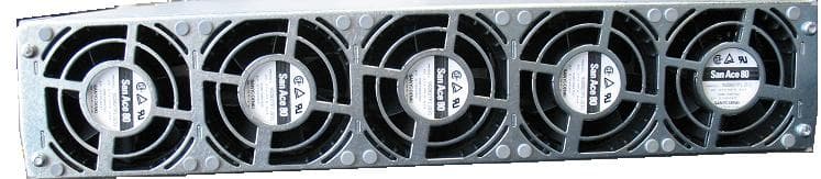
IHET5GX1
Oct 14, 2007UBS CDMA XMI Transceiver at 800 MHz
Equipment Class
TNB - Licensed Non-Broadcast Station Transmitter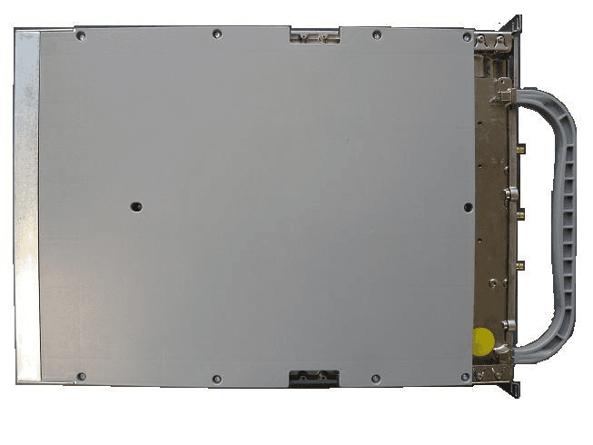
IHET6HG1
Sep 12, 2007CDMA Base Station
Equipment Class
PCB - PCS Licensed Transmitter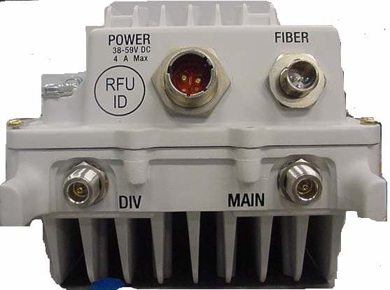
IHET7HN1
Jul 17, 20072.5 GHz Diversity Access Point
Equipment Class
TNB - Licensed Non-Broadcast Station Transmitter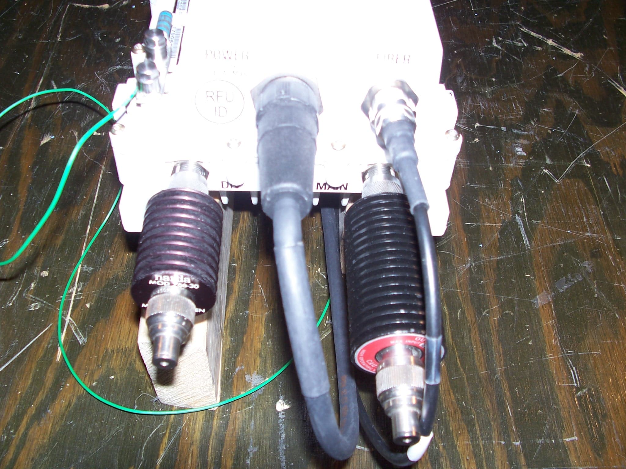
IHET7GT1
Jan 14, 20072.5GHz DIVERSITY ACCESS POINT
Equipment Class
TNB - Licensed Non-Broadcast Station Transmitter