IHET7GT12.5GHz DIVERSITY ACCESS POINT
Nokia Solutions and Networks
Click to zoom
Application Details
- Equipment Class
- TNB - Licensed Non-Broadcast Station Transmitter
- Date of Grant
- Jan 14, 2007
- Application Purpose
- Original Equipment
- Date of Application
- Jan 11, 2007
- Equipment Note
- 2.5GHz DIVERSITY ACCESS POINT
- Frequency Range
- 2496.00000000 - 2690.00000000
- Company
- Nokia Solutions and Networks
- Country
- United States
Documents & Files
Document Text
Text extracted from the exhibit documents filed with the FCC. Open a document above to read the original.
Users Manual
M APPLICANT: MOTOROLA Networks FCC ID: IHET7GT1 FCC Filing – WAP25400 MOTOwi4™ Diversity Access Point @ 2.5 GHz 1 of 1 Users Manual Exhibit 2.5GHz Diversity Access Point Notice Whilereasonableeffortshavebeenmadetoassuretheaccuracyofthisdocument,Motorola, Inc.assumesnoliabilityresultingfromanyinaccuraciesoromissionsinthisdocument,or fromuseoftheinformationobtainedherein.Theinformationinthisdocumenthasbeen carefullycheckedandisbelievedtobeentirelyreliable.However,noresponsibilityisas- sumedforinaccuraciesoromissions.Motorola,Inc.reservestherighttomakechangesto anyproductsdescribedhereinandreservestherighttorevisethisdocumentandtomake changesfromtimetotimeincontenthereofwithnoobligationtonotifyanypersonofrevi- sionsorchanges.Motorola,Inc.doesnotassumeanyliabilityarisingoutoftheapplication oruseofanyproduct,software,orcircuitdescribedherein;neitherdoesitconveylicense underitspatentrightsortherightsofothers. Itispossiblethatthispublicationmaycontainreferencesto,orinformationaboutMotorola products(machinesandprograms),programming,orservicesthatarenotannouncedin yourcountry.SuchreferencesorinformationmustnotbeconstruedtomeanthatMotorola intendstoannouncesuchMotorolaproducts,programming,orservicesinyourcountry. Copyrights Thisinstructionmanual,andtheMotorolaproductsdescribedinthisinstructionmanualmay be,includeordescribecopyrightedMotorolamaterial,suchascomputerprogramsstored insemiconductormemoriesorothermedia.LawsintheUnitedStatesandothercountries preserveforMotorolaanditslicensorscertainexclusiverightsforcopyrightedmaterial,in- cludingtheexclusiverighttocopy,reproduceinanyform,distributeandmakederivative worksofthecopyrightedmaterial.Accordingly,anycopyrightedmaterialofMotorolaandits licensorscontainedhereinorintheMotorolaproductsdescribedinthisinstructionmanual maynotbecopied,reproduced,distributed,mergedormodifiedinanymannerwithoutthe expresswrittenpermissionofMotorola.Furthermore,thepurchaseofMotorolaproducts shallnotbedeemedtogranteitherdirectlyorbyimplication,estoppel,orotherwise,any licenseunderthecopyrights,patentsorpatentapplicationsofMotorola,asarisesbyoper- ationoflawinthesaleofaproduct. UsageandDisclosureRestrictions LicenseAgreements ThesoftwaredescribedinthisdocumentisthepropertyofMotorola,Incanditslicensors. Itisfurnishedbyexpresslicenseagreementonlyandmaybeusedonlyinaccordancewith thetermsofsuchanagreement. CopyrightedMaterials Softwareanddocumentationarecopyrightedmaterials.Makingunauthorizedcopiesispro- hibitedbylaw.Nopartofthesoftwareordocumentationmaybereproduced,transmitted, transcribed,storedinaretrievalsystem,ortranslatedintoanylanguageorcomputerlan- guage,inanyformorbyanymeans,withoutpriorwrittenpermissionofMotorola,Inc. HighRiskMaterials Components,units,orthird-partyproductsusedintheproductdescribedhereinareNOT fault-tolerantandareNOTdesigned,manufactured,orintendedforuseason-linecontrol equipmentinthefollowinghazardousenvironmentsrequiringfail-safecontrols:theopera- tionofNuclearFacilities,AircraftNavigationorAircraftCommunicationSystems,AirTraffic Control,LifeSupport,orWeaponsSystems(HighRiskActivities).Motorolaanditssup- plier(s)specificallydisclaimanyexpressedorimpliedwarrantyoffitnessforsuchHighRisk Activities. Trademarks MotorolaandtheStylizedMLogoareregisteredintheUSPatent&TrademarkOffice.All otherproductorservicenamesarethepropertyoftheirrespectiveowners. DraftOCT2006 Table of Contents Contents ■■■■■■■■■■■■■■■■■■■■■■■■■■■■■■■■■■■■■■■■■■■■■■■■■■■■■■■■■■■■■■ ■ ■ ■ ■ AccessPointHardwareInstallation RevisionHistory.........................................2 VersionInformation.....................................2 Generalinformation.....................................2 ContactingMotorola.......................................5 Errors............................................5 Questionsandcomments..................................5 24hoursupport.......................................5 SecurityAdvice.........................................6 Warningsandcautions......................................7 Failuretocomplywithwarnings...............................7 Warnings...........................................7 Cautions...........................................7 Notes............................................8 GeneralSafety..........................................9 Groundtheequipment....................................9 Donotoperateinanexplosiveatmosphere.........................9 Keepawayfromlivecircuits.................................9 Donotserviceoradjustalone................................9 UsecautionwhenexposingorhandlingtheCRT.......................10 Donotsubstitutepartsormodifyequipment........................10 Potentiallyhazardousprocedurewarnings..........................10 Devicessensitivetostatic....................................11 Specialhandlingtechniques.................................11 Caringfortheenvironment...................................12 DisposalofMotorolaNetworksequipmentinEUcountries.................12 DisposalofMotorolaNetworksequipmentinnon-EUcountries...............12 ThirdPartyComputerSoftwareandTrademarks........................13 ComputerSoftware.....................................13 Trademarks.........................................13 Motorolamanualset.......................................14 OrderingmanualsandCD-ROMs..............................14 Manualbannerdefinitions..................................14 Chapter1:Introduction Introduction...........................................1-2 Overview...........................................1-2 ManualOrder........................................1-2 ProductDescription.....................................1-3 RecommendedDocuments..................................1-3 AbbreviationsandAcronyms.................................1-3 ToolsandMaterials.......................................1-5 68P09277A59-5i OCT2006Draft Contents Introduction.........................................1-5 ToolsandMaterials.....................................1-5 BaseControlUnitHardwareIdentification......…
Text truncated - open the document above for the full version.
Users Manual
AccessPointHardwareInstallationAccessPointEquipmentIdentication Figure1-3BCUHardware ti-cdma-04197.eps Alarm Card Fan Tray BCU Chassis I/O Panel Pole Mount Bracket Heater Circuit Breaker CardModem Card CardController Card PSU 68P09277A59-51-9 DraftOCT2006 AccessPointEquipmentIdenticationChapter1:Introduction RFHeadHardwareIdentication TheDiversityAccessPoint(DAP)RFHeadAssemblyconsistsofatwoantennaelementusinga singleradomeanda(oneTransmit/ReceiveRFModule(RFHead)). Figure1-4DAPRFHeadHardware ti-cdma-04168.eps RF Head DC Power Fiber Optic RF Connector Ground Radome RF Connector Access Panel 1-1068P09277A59-5 DraftOCT2006 Chapter 2 SitePreparation ■■■■■■■■■■■■■■■■■■■■■■■■■■■■■■■■■■■■■■■■■■■■■■■■■■■■■■■■■■■■■■ ■ ■ ■ ■ 68P09277A59-52-1 OCT2006Draft SitePreparationOverviewChapter2:SitePreparation SitePreparationOverview ■■■■■■■■■■■■■■■■■■■■■■■■■■■■■■■■■■■■■■■■■■■■■■■■■■■■■■■■■■■■■■ ■ ■ Overview Thischapterprovidestheproceduresandinformationtoverifythatthesiteisreadyfor equipmentinstallation.Italsoprovidesprocedurestoensurethesafetyoftheinstallation personnel,protecttheequipmentfromdamage,andverifythesitelayoutparameters. Everyeffortshouldbemadetoprovideasafeworkingenvironmentforallinstallation andservicepersonnel. Installation ThisBaseControlUnit(BCU)maybeinstalledindoorsoroutdoors.TheRFHeadisinstalled outdoors.Thesitepreparationdependsonthetypeofinstallationandthesitecharacteristics. SiteManager Thesitemanageristhepersoninchargeofandresponsibleforthefullsite. VericationandProcedures Verificationstypicallyhavetheinstallercheckwiththesitemanagerthataconditionhasbeen previouslycheckedorprocedurepreviouslyperformedandmeetsastatedspecification. Inspectionstypicallyhavetheinstallerpersonallycheckingthataconditionoritemmeets statedspecifications. Theverificationsandproceduresprovidedinthischapterare: •Internalsiteinspections •Preparingsiteforthearrivalofequipment •Sitelayoutverification 2-268P09277A59-5 DraftOCT2006 AccessPointHardwareInstallationPrepareSiteforEquipmentArrival PrepareSiteforEquipmentArrival ■■■■■■■■■■■■■■■■■■■■■■■■■■■■■■■■■■■■■■■■■■■■■■■■■■■■■■■■■■■■■■ ■ ■ Description Thisinformationcoversvarioustopicsnotallofwhichareneededateverysite.Basedonthe sitecharacteristicsexecutethestepsthatapplytoyoursite.Beforeinstallingtheequipment,do thefollowingtoensurethesafetyofinstallationpersonnelandtoprotecttheequipment. EquipmentArrival Beforetheequipmentarrives,indicatetothetransportcompanyanareaatthesitewherethe equipmentcanbeunloadedand,ifnecessary,unpacked.Theequipmentshouldbecarefully deliveredtothesite,alongwithallequipmentdolliesandpaddingrequiredtosafelymovethe equipmentfromtheunloadingareatothecellsite.Thefollowingshouldalsobeprovided, outdoorweatherprotection,temporarylightingandpowerforlightingandpowertools. ProceduretoPreparetheSitefortheEquipment Procedure2-1ProceduretoPreparetheSitefortheBTS 1 Consultwithsitemanager. 2 Locatethedemarcationblocksforexternalutilities. VerifythattheyareshownontheSiteEngineeringdocuments,and determinetherequiredcableroutingbacktotheequipmentframes. 3 Verifythefollowing: •ACpowerisavailableandmeetsthesitedocumentationspecifications •Poleand/orwallmountingstructuresareadequate •Outdoorcablerunsareinstalledandmeetlocalbuildingcodes •Customerinputterminationtiepointsareavailable •Thereisclearaccesstomovetheequipmenttothedesiredmounting area •Thereissufficientspaceforinstallationandserviceaccesstothe equipment •Customersuppliedsheltersareinstalled 68P09277A59-52-3 DraftOCT2006 ShippingandHandlingChapter2:SitePreparation ShippingandHandling ■■■■■■■■■■■■■■■■■■■■■■■■■■■■■■■■■■■■■■■■■■■■■■■■■■■■■■■■■■■■■■ ■ ■ Overview ThepurposeofthischapteristodescribehowtheBaseControlUnit(BCU)andRFHeadare packagedforshippingandhowtocorrectlyunpacktheunitsinpreparationforinstallation. HowEquipmentisShipped TheBCUandRFHeadwillbeshippedinseparatecontainersorseparatepallets.The containers,ifusedwilleitherbewoodorcardboard,withpackingmaterialtoprotecttheunits. Ifpalletsareused,theunitswillbewrappedinpackingmaterialandstrappedtothepallet. Plasticwrappingwillbeusedtoencasetheunitsandprovideprotectionaswellassecuringthe unitstothepallets. TheBCUisshippedwithallcards/modulesandinternalcablinginstalled. TheRFHeadisshippedfullyassembled. HowEquipmentArrives Beforetheequipmentarrives,indicatetothetransportcompanyanareaatthesitewherethe equipmentcanbeunloadedand,ifnecessary,unpacked.Theequipmentshouldbecarefully deliveredtothesite,alongwithallequipmentdolliesandpaddingrequiredtosafelymovethe equipmentfromtheunloadingareatothecellsite.Thesiteshouldalsohavethefollowingitems available:outdoorweatherprotectionandpowerfortemporarylightingandpowertools. Unpacking Theunpackingprocessrequiresthatthefollowingproceduresbecompletedintheordershown: 1.Unpacktheshippingcontainer 2.Inventorytheshippingcontainer 3.Inspectequipmentfordamage RecommendedTools ThetoolsinTable2-1arerecommendedtoassistinopeningthecontainershousingthe equipment.TinsnipsKnife,boxcutter,orscissors 2-468P09277A59-5 DraftOCT2006 AccessPointHardwareInstallationShippingandHandling Table2-1RecommendedUnpackingTools Qty Description 1Tinsnips 1 Knife,boxcutter,scissors UnpackingDiagrams Thefollowingdiagramsshowhowtounpacktheequipment. Figure2-1ShrinkWrappedShipment AuthorsNote:Figure2–1willbenewandFigure2–2willbechanged. 68P09277A59-52-5 DraftOCT2006 ShippingandHandlingChapter2:SitePreparation Figure2-2CardboardShippingContainer ti-cdma-04170.eps NOTE: 1.Normallythisstyrofoam packingisattachedtothe pallet.itisshownexploded forclarity 2.ThisexampleshowstheBCU Styrofoam Packing 1 Cardboard Box BCU Styrofoam Packing CardboardLid WoodPallet 2-668P09277A59-5 DraftOCT2006 AccessPointHardwareInstallationShippingandHandling UnpackingaCardboardContainerorShrinkWrappedShipment FollowtheprocedureinProcedure2-2tounpackequipmentfromacontainerorshrinkwrap. Procedure2-2UnpackingEquipmentfromaCardboardContainerorShrinkWrap 1 Inspectfordamage. Componentsmayormaynotbedeliveredononepallet.Procedure assumescomponentsaredeliveredinseparatecontainersonone…
Text truncated - open the document above for the full version.
Users Manual
CableDescriptionsChapter3:CableDescriptions CableDescriptions ■■■■■■■■■■■■■■■■■■■■■■■■■■■■■■■■■■■■■■■■■■■■■■■■■■■■■■■■■■■■■■ ■ ■ Overview Thischapterprovidesthedescriptionsofthesitecabling. Proceduresforroutingcables(throughmetallicorconductiveconduit)totheoutdoorequipment arefoundinChapter4AccessPointHardwareInstallation. Cablingisoneofthemostnoticeableaspectsofworkmanship.Straightrunsand properturnsarecriticalforapositiveevaluationofthework. CongurationsSupported Thischaptersupportscableinstallationfor3and4sectorconfigurations. CableInstallationOrder 1.GroundCabling 2.PowerCabling 3.AntennaCabling 4.RGPSorRFGPSCabling 5.EthernetCabling 6.FiberOpticCabling 7.CustomerDefinedInput/OutputCabling CableLabels RefertoTable3-1forthelabelsusedtoidentifythecablesthatwillbeshowninillustrations throughoutthischapter. 3-268P09277A59-5 DraftOCT2006 AccessPointHardwareInstallationCableDescriptions CableDescriptionsandPartNumbers Table3-1givesthecabledescriptionsandpartnumbersofthevariouscablesthatwillconnect totheBaseControlUnit(BCU)andRFhead. Table3-1CableDescriptionandPartNumbers CableQty PartNumberDescription A 2 CustomerSuppliedGroundcable,6AWGorlarger,insulatedcopper wire.Requiresonetwo-holelugconnectors. B 2–83089492T02 AntennaCable,300mm(1ft.) C1T472AA RGPScable,15m(50ft.) T472AB RGPScable,38m(125ft.) T472AC RGPScable,76m(250ft.) T472AD RGPScable,152m(500ft.) T472AE RGPScable,304m(1000ft.) T472AF RGPScable,608m(2000ft.) C11SGKN4386 PunchblocktoCBIOBoard,15pinD-connectoron oneendandloosewiresontheotherend.Cableis MotorolaP/N3086433H12. D 1SGRG4030A CGDSGPSKITF4NM50 Assembly,Receiver,GPS,RFModule Antenna,GPS,withmountingand50ft. cable. E 2 CustomerSuppliedACPowerCable,10AWG,copper F 1SGLN6414A Assembly,Installation,InstallationHDWPkgBCU G1–43089298C01—05 RFHeadDCPowerCable H 1–43089843T01—05 FiberOpticCable J 6 CustomerSuppliedEthernetcables,RJ-45connectors,straight K 1SGRG4030A CGDSGPSKITF4NM50 Assembly,Receiver,GPS,RFModule Antenna,GPS,withmountingand50ft. cable. 68P09277A59-53-3 DraftOCT2006 CableDescriptionsChapter3:CableDescriptions CableLengths Table3-2CableLengthRequirements FromTo CableDesignationCablelength BCUDCSource RFHeadDC Connector G 5lengths,20to100min20m increments(65.6to328ft) BCURFConnector RFHeadRF Connector B 300mm(1ft) ACSourceBCUCustomer Interface Compartment E Lengthasrequired. CustomerOutput Source BCUCustomer Interface Compartment F Lengthasrequired. 3-468P09277A59-5 DraftOCT2006 AccessPointHardwareInstallationEarthGroundandPowerCables EarthGroundandPowerCables ■■■■■■■■■■■■■■■■■■■■■■■■■■■■■■■■■■■■■■■■■■■■■■■■■■■■■■■■■■■■■■ ■ ■ TheobjectiveofthisprocedureistoinstallthepowerandearthgroundcablingfortheBase ControlUnit(BCU)andRFHead. GroundingConsiderations AboveGroundForgroundringsandtheinterconnectionofinternalandexternalground rings,#2to#6AWGmaybeused.Forgroundingofequipmentandmiscellaneousmetallic objects,#6AWGminimumisrequired. ExceptionsConnectionfromanisolatedgroundbar(IGB)tomastergroundbar(MGB)is accomplishedusing#2to#6AWG.Theexternalgroundbar(EGB)isgroundedthrougha2-inch wide,16-gaugecopperstrap,ifavailable;otherwise,2-#6AWGwirescanbeused.Ifthe#6 AWGwiresareused,thentheymustbeconnectedatoppositeendsoftheEGBandhavea minimumseparationof12-inchesbetweenthem. BelowGroundAllwiremustbe#2AWGasaminimum.Groundrodsaretobeaminimumof 8feetlongand5/8-inchindiameter.Inthecaseofadeepbasementnexttotherod,therod mustbelongenoughtoextend3feetbelowthebasementfloor. PowerConsiderations TheBaseControlUnit(BCU)isdesignedfor100/240VAC(88–300Vrms)@45–66Hz,+21 to+30VDCor—60to—40VDC. Thesystemconfigurationdetermineswhichpowercablesareinstalled.Thegroundcableis alwaysinstalledfirst.Basedonthesystemconfigurationperformtheappropriateprocedures describedinChapter4AccessPointHardwareInstallation. DCPower(RFHead) TheDCpowercableisorderableinavarietyoflengthsasindicatedinTable3-3below. Dependingonsiteconfigurationallofonelengthoracombinationoflengths(upto4)maybe used. 68P09277A59-53-5 DraftOCT2006 EarthGroundandPowerCablesChapter3:CableDescriptions Table3-3RFHeadDCPowerCableDescriptionandPartNumbers CableQty PartNumberDescription F 1–43089298C01 PowerCable,20m(65.6ft) 1–43089298C02 PowerCable,40m(131.2ft) 1–43089298C03 PowerCable,60m(196.8ft) 1–43089298C04 PowerCable,80m(262.4ft) 1–43089298C05 PowerCable,100m(328.0ft) 3-668P09277A59-5 DraftOCT2006 AccessPointHardwareInstallationAntennaCable AntennaCable ■■■■■■■■■■■■■■■■■■■■■■■■■■■■■■■■■■■■■■■■■■■■■■■■■■■■■■■■■■■■■■ ■ ■ Objective Thissectioncontainsgeneralinformationontheantennacabling. CableLabel RefertoTable3-1forthelabelsusedtoidentifythecablesthatwillbeshowninillustrations throughoutthischapter. Table3-4CableDescriptionandPartNumbers CableQty PartNumberDescription B 2–43089492T02 AntennaCable,300mm(1ft.) AntennaCablePinandSignalInformation Theantennacablingusesa50-Ohmcoaxialcable.Theinnerconductorprovidessignalingand theouterconductorprovidesshieldingandground. Figure3-1AntennaCableDetail Table3-5PinandSignalInformationforAntennaCable Antenna InnerConductorOuterConductor BTX/RX Ground 68P09277A59-53-7 DraftOCT2006 RemoteGPSCableChapter3:CableDescriptions RemoteGPSCable ■■■■■■■■■■■■■■■■■■■■■■■■■■■■■■■■■■■■■■■■■■■■■■■■■■■■■■■■■■■■■■ ■ ■ Objective ThissectioncontainsgeneralinformationontheRemoteGlobalPositioningSystem(RGPS) cabling.InstallationinformationisfoundinChapter4AccessPointHardwareInstallation, beginningwithProcedure4-6. CableLabel RefertoTable3-1forthelabelsusedtoidentifythecablesthatwillbeshowninillustrations throughoutthischapter.CableCisavailableindifferentkitscoveringseverallengths. RGPSCables Table3-6providesthequantitiesanddescriptionsofthecables. Table3-6CablesNeededforRGPSConnections CableQty PartNumberDescription C1T472AA RGPScable,15m(50ft.) T472AB RGPScable,38m(125ft.) T472AC RGPScable,76m(250ft.) T472AD RGPScable,152m(500ft.) T472AE RGPScable,304m(1000ft.) T472AF RGPScable,608m(2000ft.) C11SGKN4386 15pinD-connectorononeendandloose wiresontheotherend.CableisMotorola P/N3086433H12. MountingConsiderations TheRGPSHeadrequiresspe…
Text truncated - open the document above for the full version.
Users Manual
AccessPointHardwareInstallationGroundCablingInstallation RGPSGrounding Figure4-6TypicalOutdoorGroundingDiagram ti-cdma-04180.eps DCPrimarySurgeArrestors Backhaul&CustomerI/O SurgeArrestor ACPrimarySurgeProtector BondedGround/Earth Connection Conduitor ShieldedCable LPZ1 LPZ2SecondaryProtectedZone LPZ0 A LPZ0 B AntennaTower 45Degree IECRecommended DirectStrike ProtectionAngle RF 1 RF 2 RF 3 BCU BACKHAUL CSU ACInput Backhaul MASTERSINGLE POINTEQUIPMENT GROUND LPZ0 A --Possibledirectstrikezone LPZ0 B --Nodirectstrike,but unattenuatedelectromagneticfield present LPZ1PrimaryProtectedZone LPZ1 LPZ2 LPZ 2 LPZ 2 LPZ 2 CustomerI/O 68P09277A59-54-21 DraftOCT2006 GroundCablingInstallationChapter4:AccessPointHardwareInstallation Figure4-7TypicalIndoorGroundingDiagram ti-cdma-04181.eps DCPrimarySurgeArrestors SecondarySurgeArrestor AC&BackhaulPrimary SurgeArrestor BondedGround/Earth Connection Conduitor ShieldedCable LPZ1 LPZ2SecondaryProtectedZone LPZ0 A LPZ0 B AntennaTower 45Degree IECRecommended DirectStrike ProtectionAngle RF 1 RF 2 RF 3 BCU INSULATOR CustomerI/O MASTERSINGLE POINTSTRUCTURE GROUND LPZ0 A --Possibledirectstrikezone LPZ0 B --Nodirectstrike,but unattenuatedelectromagneticfield present LPZ1PrimaryProtectedZone LPZ2 LPZ 2 LPZ 2 LPZ 2 SinglePoint Ground ACInput Backhaul STRUCTURE 4-2268P09277A59-5 DraftOCT2006 AccessPointHardwareInstallationACPowerCablingInstallation ACPowerCablingInstallation ■■■■■■■■■■■■■■■■■■■■■■■■■■■■■■■■■■■■■■■■■■■■■■■■■■■■■■■■■■■■■■ ■ ■ Objective ThissectioncontainstheprocedureforinstallingtheACpowercable. Thisequipmentusesdangerousvoltagesandiscapableofcausingdeath.Useextreme cautionwhenhandlingandtestingthisequipment.Earthconnectionisessentialbefore connectingthepowerduetothepresenceofhighearthleakagecurrent. ACCableDescription CableEaslistedinTable3-1isrequiredforthisinstallation. Theminimumbendradiusforthiscableis90mm. ToolsRequired ThefollowingtoolsarerequiredtoinstalltheACpowercables. •No.2Bladescrewdriver ACPowerConnectionProcedure FollowthestepsinProcedure4-4toconnecta100/240VAC(88–300Vrms)SinglePhaseAC powercabletotheBaseControlUnit(BCU).TheACpowercablewillberoutedthroughoneand one-halfinchconduittotheappropriateaccessholeontheundersideoftheBCU. Continued 68P09277A59-54-23 DraftOCT2006 ACPowerCablingInstallationChapter4:AccessPointHardwareInstallation Procedure4-4ProceduretoInstallACPowerCable 1 EnsurethatACpoweratthesourceisdisabledbeforehandlingcable. 2 Ifnotalreadydone,routeACpowercablesthroughconduittoBCUCustomer Interfacecompartment. 3 IntheBCUCustomerInterfacecompartment,opentheACpowercover,by looseningtwocaptivescrews.ACPowercoverishinged. 4 LoosenscrewsonACpowercircuitbreakerterminalblock.Insert ACpowercablesintoLINEandNEUTRALandtightenscrews. Ensureagoodconnection. 5 CloseACpowercoverandsecurebytighteningtwocaptivescrews. Figure4-8BCUACPowerConnection ti-cdma-04182.eps Neutral Connectio n Line Connection 4-2468P09277A59-5 DraftOCT2006 AccessPointHardwareInstallationRFHeadDCPowerCablingInstallation RFHeadDCPowerCablingInstallation ■■■■■■■■■■■■■■■■■■■■■■■■■■■■■■■■■■■■■■■■■■■■■■■■■■■■■■■■■■■■■■ ■ ■ Objective ThissectioncontainstheprocedureforinstallingtheRFHeadDCpowercables. DCCableDescription CableGlistedinTable3-1isrequiredforinstallation ToolsRequired ThefollowingtoolsarerequiredtoinstalltheDCPowercables. DCPowerCableInstallation FollowthestepsinProcedure4-5toinstalltheDCPowerCables. Procedure4-5ProceduretoInstallDCPowerCables 1 Ifnotalreadyopen,opentheBCUCustomerInterfacecompartment. 2 BeforeroutingDCpowercable,verifythatitisproperlycolorcoded.Ifmore thanoneRFHeadinuse,ensurethattheyareallproperlycolorcoded. Colorcodedlabelsandtie-wrapscanbefoundonthe compartmentsideofthedooroftheBCUCustomerInterface compartment.Tie-wrapsshouldbeattachedneartheconnnector. 3 ConnecttheDCpowercablestoconnectorRFU1—RFU4,asrequired. 4 RoutetheDCPowercablesthroughconduituptothetower.Bundleand securethecables(ifRFHeadisnotpresent)orconnecttotheappropriate RFHead. 68P09277A59-54-25 DraftOCT2006 RFHeadDCPowerCablingInstallationChapter4:AccessPointHardwareInstallation Figure4-9BaseControlUnitDCPowerConnection ti-cdma-04183.eps RFU 1, RFU 2, RFU 3, RFU4 CAUTION LIVE TERMINALS CAUTION PRIOR TO INSTALLATION/REMOVAL OF WIRE TO TERMINAL BLOCK. ASSOCIATED CIRCUIT BREAKER TO BE DISENGAGED +54VDC RETUR N +54VDC RETUR N +54VDC RETUR N +54VDC RETUR N RFU 1RFU 3RFU 4RFU 2 4-2668P09277A59-5 DraftOCT2006 AccessPointHardwareInstallationAntennaCablingInstallation AntennaCablingInstallation ■■■■■■■■■■■■■■■■■■■■■■■■■■■■■■■■■■■■■■■■■■■■■■■■■■■■■■■■■■■■■■ ■ ■ Objective Thissectioncontainstheprocedureforinstallingtheantennacables. InstallingAntennaCables TheantennacableswillalreadybeinstalledbetweentheantennaandtheRFHead. 68P09277A59-54-27 DraftOCT2006 RGPSCablingInstallationChapter4:AccessPointHardwareInstallation RGPSCablingInstallation ■■■■■■■■■■■■■■■■■■■■■■■■■■■■■■■■■■■■■■■■■■■■■■■■■■■■■■■■■■■■■■ ■ ■ Objective ThissectioncontainsproceduresforinstallingtheRemoteGlobalPositioningSystem(RGPS). CableDescription CablesCandC1aslistedinTable3-1arerequiredforinstallation. ToolsRequired CablePinout Figure4-10ConnectorPinsNumberingforCablesCandC1 ti-cdma-04196.eps 1 2 3 4 5 6 7 8 9 10 1112 CONNECTOR FOR CABLE C PIN 1 CONNECTOR FOR CABLE C1 PIN 9 4-2868P09277A59-5 DraftOCT2006 AccessPointHardwareInstallationRGPSCablingInstallation Table4-4PinoutforCablesCandC1 CableCCableC1 PinNo. SignalNameWireColor ConnectorA PinNo. SignalName ConnectorB PinNo. 9 DCGround1Blue–Black 15RGPSReturn15 1Power1 Blue 8 RGPS+54VSupply 8 8 DCGround2Yellow–Black 14RGPSReturn14 10Power2 Yellow 7 RGPS+54VSupply 7 4 TransmitPort(–)Green–Black 9 DATA(-)FromHead 12 5 TransmitPort(+) Green1 DATA(+)FromHead 4 2 ReceivePort(–)White–Black 12 DATA(-)ToHead 9 3 ReceivePort(+)White 4 DATA(+)ToHead 1 7 NoConnect Red–Black NoConnectNoConnectNoConnect 6NoConnect Red NoConnectNoConnectNoConnect 12 PPSTiming(–)Brown–Black 10 SYNC(-)FromHead 10 11 PPSTiming(+) Brown 2 SYNC(+)FromHead 2 RGPSInstallation Figure4-11showstheRFGPSHeadandFigure…
Text truncated - open the document above for the full version.
Cover Letter(s)
M APPLICANT: MOTOROLA Networks FCC ID: IHET7GT1 FCC Filing – WAP25400 MOTOwi4™ Diversity Access Point @ 2.5 GHz 1 of 2 December 11, 2006 Federal Communications Commission Authorization & Evaluation Division 7435 Oakland Mills Road Columbia, Maryland 21046 Re: Application for Cellular Transceiver Certification To Whom it may Concern: Motorola Inc., 1475 W. Shure Drive, Arlington Heights, Illinois 60004, herein submits: Filing fee, Application for Equipment Authorization (FCC Form 731) and Sections for Certification of a WiMAX Transceiver, FCC ID: IHET7GT1. Motorola is also the manufacturer of this equipment. Motorola requests that the following Exhibits be kept confidential pursuant to 47CFR Parts 0.459 and 0.457: • Descriptive Information • Internal Photos • Parts Lists • Schematics • Block Diagram These materials contain trade secrets and proprietary information and are not customarily released to the public. The public disclosure of this information might be harmful to the company and provide unjustified benefits to our competitors. Additionally, internal photos are eligible for confidentially since the product is a non-consumer device, is not accessible by the general public, and is only accessible by the licensee or his designated technicians. The confidential portions have been identified as such on the Uploading Sections Form. The filing fee includes $145.00, the amount for a confidential filing. Please contact me by telephone at (847) 435-9487, by Fax at (847) 632-5936, or by correspondence at the address herein if there are further questions or if additional information is needed concerning this filing. Regards, 12/11/2006 Scott Munier Senior Resource Manager Customer Integration Engineering M APPLICANT: MOTOROLA Networks FCC ID: IHET7GT1 FCC Filing – WAP25400 MOTOwi4™ Diversity Access Point @ 2.5 GHz 2 of 2
ID Label/Location Info
M Label Exhibit Networks FCC ID: IHET7GT1 FCC Filing – WAP25400 MOTOwi4™ Diversity Access Point @ 2.5 GHz Page 1 of 1 Equipment Label and Placement Equipment Nameplace per CFR, Title 47, Part 2.925 The label shown below (or one simila r to it) will be affixed to the e quipment in the location indicated.
Parts List/Tune Up Info
M Networks FCC ID: IHET7GT1 FCC Filing – WAP25400 MOTOwi4™ Diversity Access Point @ 2.5 GHz 1 FCC FILING FOR 2.5GHz OFDMA MOTOwi4™ Diversity Access Point Tune up procedures; The access point transmitter output power is tuned and set per database parameters using factory generated internal calibration tables and requires no specific procedure during site commissioning. The corresponding TX gain of each AP determined by these parameters remains unchanged during normal operation.
RF Exposure Info
M APPLICANT: MOTOROLA Networks FCC ID: IHET7GT1 FCC Filing – WAP25400 MOTOwi4™ Diversity Access Point @ 2.5 GHz 1 of 1 Prediction of MPE Limit at a given distance Calculate the Maximum Personal Exposure (MPE) limits for the BTS for both Occupational/Controlled Exposure and General Population/Uncontrolled Exposure limits (for average exposure < 6 minutes) Value is calculated at the maximum PO available (30.25dBm) This takes into account the minimum antenna feed line loss. MPE limits will be calculated Using Equation from page 18 of OET Bulletin 65, Edition 97-01 Where: S = power density P = power input to the antenna G = power gain of the antenna in the direction of interest relative to an isotropic radiator R = distance to the center of radiation of the antenna Maximum peak output power at antenna input terminal: 30.25 (dBm) Maximum peak output power at antenna input terminal: 1059.25 (mW) Antenna gain (typical): 16 (dBi) Maximum antenna gain: 39.81071706 (numeric) General Population/Uncontrolled Exposure Prediction distance: 66 (cm) or approximately 26 inches Prediction frequency: 2600 (MHz) MPE limit for General Population/Uncontrolled Exposure at prediction frequency: 1 (mW/cm^2) Power density at prediction frequency: 0.9703 (mW/cm^2) Occupational/Controlled Exposure Prediction distance: 30 (cm) or approximately 12 inches Prediction frequency: 2600 (MHz) MPE limit for Occupational/Controlled Exposure at prediction frequency: 5 (mW/cm^2) Power density at prediction frequency: 4.6964 (mW/cm^2) Note: MPE limits that are provided to the customer and only serve as a guideline. The site license holder is ultimately responsible for MPE compliance at a given site.
Test Report
M APPLICANT: MOTOROLA Networks FCC ID: IHET7GT1 FCC Filing – WAP25400 MOTOwi4™ Diversity Access Point @ 2.5 GHz 1 of 4 TEST REPORT EXHIBIT Placeholder for Nemko Report / Summary Index Section Description A Summary of RF Measurements B Spurious & Harmonic Emissions Radiated C Spurious & Harmonic Emissions Conducted D Occupied Bandwidth E MPE Exposure F Frequency Stability M APPLICANT: MOTOROLA Networks FCC ID: IHET7GT1 FCC Filing – WAP25400 MOTOwi4™ Diversity Access Point @ 2.5 GHz 2 of 4 Section F Frequency Stability M APPLICANT: MOTOROLA Networks FCC ID: IHET7GT1 FCC Filing – WAP25400 MOTOwi4™ Diversity Access Point @ 2.5 GHz 3 of 4 Frequency Stability Over Temperature - 10MHz TDD mode -2.5 -2 -1.5 -1 -0.5 0 0.5 1 1.5 2 2.5 -30-20-1001020304050 Frequency Delta (ppm) Temperature (C) Frequency Stability with Varying Supply Voltage - 10MHz TDD mode -2.5 -2 -1.5 -1 -0.5 0 0.5 1 1.5 2 2.5 85%90%95%100%105%110%115% Frequency Delta (ppm) Pow er Supply Voltage (%) M APPLICANT: MOTOROLA Networks FCC ID: IHET7GT1 FCC Filing – WAP25400 MOTOwi4™ Diversity Access Point @ 2.5 GHz 4 of 4 Frequency Stability Over Temperature - 5MHz TDD mode -2.5 -2 -1.5 -1 -0.5 0 0.5 1 1.5 2 2.5 -30-20-1001020304050 Frequency Delta (ppm) Tem perature (C) Frequency Stability with Varying Supply Voltage - 5MHz TDD mode -2.5 -2 -1.5 -1 -0.5 0 0.5 1 1.5 2 2.5 85%90%95%100%105%110%115% Frequency Delta (ppm) Pow er Supply Voltage (%)
Test Report
Nemko Test Report: 6L0661RUS1 Applicant: Motorola 1475 W. Shure Drive Arlington Heights, IL 60004 USA Equipment Under Test: WAP25400 MOTOwi4™ Diversity Access Point @ 2.5 GHz In Accordance With: FCC PART 27, Subpart M Broadband Radio Service and Educational Broa…
Text truncated - open the document above for the full version.
Contact Information
Applicant
Steve Mitchell
Test Firm
Nemko Dallas, Inc.Michael Cantwell
Technical Specifications
| # | Rule Parts | Frequency Range | Power Output | Emission | Tolerance |
|---|---|---|---|---|---|
| 2 | 27 | 2.50 GHz - 2.69 GHz | 1 W | 5M00W7D | 1.5 ppm |
Other Applications from Nokia Solutions and Networks
IHET4KJ1
Apr 28, 2010LTE 700 MHz Public Safety Base Station Transceiver
Equipment Class
TNB - Licensed Non-Broadcast Station Transmitter
IHET5GX1
Oct 14, 2007UBS CDMA XMI Transceiver at 800 MHz
Equipment Class
TNB - Licensed Non-Broadcast Station Transmitter
IHET6HG1
Sep 12, 2007CDMA Base Station
Equipment Class
PCB - PCS Licensed Transmitter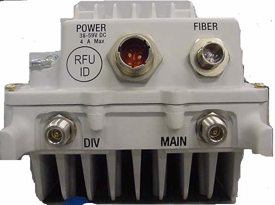
IHET7HN1
Jul 17, 20072.5 GHz Diversity Access Point
Equipment Class
TNB - Licensed Non-Broadcast Station Transmitter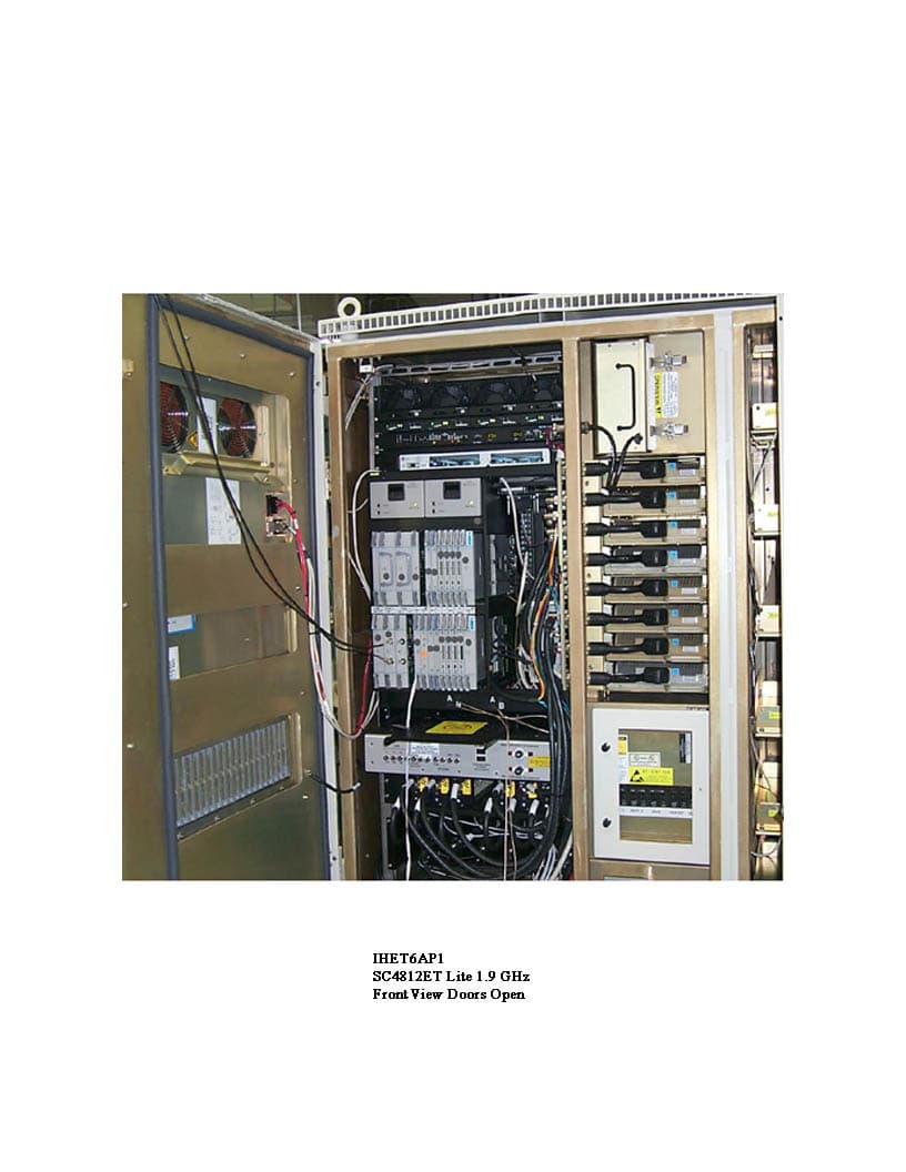
IHET6ER1
Dec 16, 2004SC4812ETLite 1.9 GHz 1X/EVDO
Equipment Class
PCB - PCS Licensed Transmitter