IHET7HN12.5 GHz Diversity Access Point
Nokia Solutions and Networks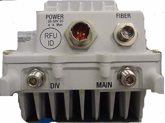
Click to zoom
Application Details
- Equipment Class
- TNB - Licensed Non-Broadcast Station Transmitter
- Date of Grant
- Jul 17, 2007
- Application Purpose
- Original Equipment
- Date of Application
- Jul 17, 2007
- Equipment Note
- 2.5 GHz Diversity Access Point
- Frequency Range
- 2496.00000000 - 2690.00000000
- Company
- Nokia Solutions and Networks
- Country
- United States
Documents & Files
Document Text
Text extracted from the exhibit documents filed with the FCC. Open a document above to read the original.
Users Manual
M APPLICANT: MOTOROLA Home & Networks Mobility FCC ID: IHET7HN1 FCC Filing – WAP25400-1 MOTOwi4™ Diversity Access Point @ 2.5 GHz 1 of 1 Users Manual Exhibit 2.5GHz Diversity Access Point AccessPointHardwareInstallation 68P09277A59-8MAY2007 PRELIMINARY-UNDERDEVELOPMENT ©2006,2007Motorola,Inc.AllRightsReserved Accuracy Whilereasonableeffortshavebeenmadetoassuretheaccuracyofthisdocument,Motorola,Inc.assumesno liabilityresultingfromanyinaccuraciesoromissionsinthisdocument,orfromuseoftheinformationobtained herein.Motorola,Inc.reservestherighttomakechangestoanyproductsdescribedhereintoimprovereliability, function,ordesign,andreservestherighttorevisethisdocumentandtomakechangesfromtimetotimeincontent hereofwithnoobligationtonotifyanypersonofrevisionsorchanges.Motorola,Inc.doesnotassumeanyliability arisingoutoftheapplicationoruseofanyproduct,software,orcircuitdescribedherein;neitherdoesitconvey licenseunderitspatentrightsortherightsofothers.Itispossiblethatthispublicationmaycontainreferencesto,or informationaboutMotorolaproducts(machinesandprograms),programming,orservicesthatarenotannounced inyourcountry.SuchreferencesorinformationmustnotbeconstruedtomeanthatMotorolaintendstoannounce suchMotorolaproducts,programming,orservicesinyourcountry. Copyrights Thisdocument,Motorolaproducts,and3rdPartySoftwareproductsdescribedinthisdocumentmayinclude ordescribecopyrightedMotorolaandother3rdPartysuppliedcomputerprogramsstoredinsemiconductor memoriesorothermedia.LawsintheUnitedStatesandothercountriespreserveforMotorola,itslicensors,and other3rdPartysuppliedsoftwarecertainexclusiverightsforcopyrightedmaterial,includingtheexclusiveright tocopy,reproduceinanyform,distributeandmakederivativeworksofthecopyrightedmaterial.Accordingly, anycopyrightedmaterialofMotorola,itslicensors,orthe3rdPartysoftwaresuppliedmaterialcontainedinthe Motorolaproductsdescribedinthisdocumentmaynotbecopied,reproduced,reverseengineered,distributed, mergedormodifiedinanymannerwithouttheexpresswrittenpermissionofMotorola.Furthermore,thepurchase ofMotorolaproductsshallnotbedeemedtogranteitherdirectlyorbyimplication,estoppel,orotherwise,any licenseunderthecopyrights,patentsorpatentapplicationsofMotorolaorother3rdPartysuppliedsoftware, exceptforthenormalnon-exclusive,royaltyfreelicensetousethatarisesbyoperationoflawinthesaleofa product. Alistof3rdPartysuppliedsoftwarecopyrightsarecontainedintheSupplementalinformationsectionofthis document. Restrictions Softwareanddocumentationarecopyrightedmaterials.Makingunauthorizedcopiesisprohibitedbylaw.Nopart ofthesoftwareordocumentationmaybereproduced,transmitted,transcribed,storedinaretrievalsystem,or translatedintoanylanguageorcomputerlanguage,inanyformorbyanymeans,withoutpriorwrittenpermission ofMotorola,Inc. LicenseAgreements ThesoftwaredescribedinthisdocumentisthepropertyofMotorola,Incanditslicensors.Itisfurnishedbyexpress licenseagreementonlyandmaybeusedonlyinaccordancewiththetermsofsuchanagreement. HighRiskMaterials Components,units,or3rdPartyproductsusedintheproductdescribedhereinareNOTfault-tolerantandareNOT designed,manufactured,orintendedforuseason-linecontrolequipmentinthefollowinghazardousenvironments requiringfail-safecontrols:theoperationofNuclearFacilities,AircraftNavigationorAircraftCommunication Systems,AirTrafficControl,LifeSupport,orWeaponsSystems(HighRiskActivities).Motorolaanditssupplier(s) specificallydisclaimanyexpressedorimpliedwarrantyoffitnessforsuchHighRiskActivities. Trademarks MotorolaandtheStylizedMLogoareregisteredintheUSPatent&TrademarkOffice.Allotherproductorservice namesarethepropertyoftheirrespectiveowners. TheCEmarkconfirmsMotorola,Inc.statementofcompliancewithEUdirectivesapplicabletothisproduct.Copies oftheDeclarationofComplianceandinstallationinformationinaccordancewiththerequirementsofEN50385can beobtainedfromthelocalMotorolarepresentativeorbycontactingtheCustomerNetworkResolutionCenter (CNRC).The24hourtelephonenumbersarelistedathttps://mynetworksupport.motorola.com.SelectCustomer NetworkResolutionCentercontactinformation.AlternativelyifyoudonothaveaccesstoCNRCorthe internet,contacttheLocalMotorolaOffice. PRELIMINARY-UNDERDEVELOPMENTMAY2007 Table of Contents Contents ■■■■■■■■■■■■■■■■■■■■■■■■■■■■■■■■■■■■■■■■■■■■■■■■■■■■■■■■■■■■■■ ■ ■ ■ ■ AccessPointHardwareInstallation Revisionhistory.........................................2 Versioninformation.....................................2 ResolutionofServiceRequests...............................2 IncorporationofChangeNotices...............................2 Generalinformation.......................................3 Purpose...........................................3 Crossreferences.......................................3 Textconventions.......................................4 ContactingMotorola.......................................5 24–hoursupport.......................................5 Questionsandcomments..................................5 Errors............................................5 Securityadvice..........................................6 Warnings,cautions,andnotes..................................7 Warnings...........................................7 Cautions...........................................7 Notes............................................7 Safety..............................................8 Generalsafety........................................8 Electromagneticenergy...................................8 Caringfortheenvironment...................................9 InEUcountries.......................................9 Innon-EUcountries.....................................9 CMMlabelinganddisclosuretable...............................10 Motoroladocumentset.....................................11 OrderingdocumentsandCD-ROMs.............................11 Documentbannerdefinitions................................11 Dataencryption.......................................11 Supplementalinformation....................................12 ThirdPartycomputersoftwareandtrademarks.......................12 FCCRequi…
Text truncated - open the document above for the full version.
Users Manual
AccessPointHardwareInstallationAccessPointEquipmentIdentication Figure1-3BCUHardware ti-cdma-04197.eps Alarm Card Fan Tray BCU Chassis I/O Panel Wall/Pole Mount Bracket Heater Circuit Breaker CardModem Card CardController Card PSU ti-cdma-04197.eps Alarm Card Fan Tray BCU Chassis I/O Panel Wall/Pole Mount Bracket Heater Circuit Breaker CardModem Card CardController Card PSU 68P09277A59-81-9 PRELIMINARY-UNDERDEVELOPMENTMAY2007 AccessPointEquipmentIdenticationChapter1:Introduction RFHeadHardwareIdentication TheDiversityAccessPoint(DAP)RFHeadAssemblyconsistsofatwoantennaelementusinga singleradomeanda(oneTransmit/ReceiveRFModule(RFHead)). Figure1-4DAPRFHeadHardware ti-cdma-04168.eps RF Head DC Power Fiber Optic RF Connector Ground Radome RF Connector Access Panel Connector Connector Location 1-1068P09277A59-8 PRELIMINARY-UNDERDEVELOPMENTMAY2007 Chapter 2 SitePreparation ■■■■■■■■■■■■■■■■■■■■■■■■■■■■■■■■■■■■■■■■■■■■■■■■■■■■■■■■■■■■■■ ■ ■ ■ ■ 68P09277A59-82-1 MAY2007PRELIMINARY-UNDERDEVELOPMENT SitePreparationOverviewChapter2:SitePreparation SitePreparationOverview ■■■■■■■■■■■■■■■■■■■■■■■■■■■■■■■■■■■■■■■■■■■■■■■■■■■■■■■■■■■■■■ ■ ■ Overview Thischapterprovidestheproceduresandinformationtoverifythatthesiteisreadyfor equipmentinstallation.Italsoprovidesprocedurestoensurethesafetyoftheinstallation personnel,protecttheequipmentfromdamage,andverifythesitelayoutparameters. Everyeffortshouldbemadetoprovideasafeworkingenvironmentforallinstallation andservicepersonnel. Installation ThisBaseControlUnit(BCU)maybeinstalledindoorsoroutdoors.TheRFHeadisinstalled outdoors.Thesitepreparationdependsonthetypeofinstallationandthesitecharacteristics. SiteManager Thesitemanageristhepersoninchargeofandresponsibleforthefullsite. VericationandProcedures Verificationstypicallyhavetheinstallercheckwiththesitemanagerthataconditionhasbeen previouslycheckedorprocedurepreviouslyperformedandmeetsastatedspecification. Inspectionstypicallyhavetheinstallerpersonallycheckingthataconditionoritemmeets statedspecifications. Theverificationsandproceduresprovidedinthischapterare: •Internalsiteinspections •Preparingsiteforthearrivalofequipment •Sitelayoutverification 2-268P09277A59-8 PRELIMINARY-UNDERDEVELOPMENTMAY2007 AccessPointHardwareInstallationPrepareSiteforEquipmentArrival PrepareSiteforEquipmentArrival ■■■■■■■■■■■■■■■■■■■■■■■■■■■■■■■■■■■■■■■■■■■■■■■■■■■■■■■■■■■■■■ ■ ■ Description Thisinformationcoversvarioustopicsnotallofwhichareneededateverysite.Basedonthe sitecharacteristicsexecutethestepsthatapplytoyoursite.Beforeinstallingtheequipment,do thefollowingtoensurethesafetyofinstallationpersonnelandtoprotecttheequipment. EquipmentArrival Beforetheequipmentarrives,indicatetothetransportcompanyanareaatthesitewherethe equipmentcanbeunloadedand,ifnecessary,unpacked.Theequipmentshouldbecarefully deliveredtothesite,alongwithallequipmentdolliesandpaddingrequiredtosafelymovethe equipmentfromtheunloadingareatothecellsite.Thefollowingshouldalsobeprovided, outdoorweatherprotection,temporarylightingandpowerforlightingandpowertools. ProceduretoPreparetheSitefortheEquipment Procedure2-1ProceduretoPreparetheSitefortheBTS 1 Consultwithsitemanager. 2 Locatethedemarcationblocksforexternalutilities. VerifythattheyareshownontheSiteEngineeringdocuments,and determinetherequiredcableroutingbacktotheequipmentframes. 3 Verifythefollowing: •ACpowerisavailableandmeetsthesitedocumentationspecifications •Poleand/orwallmountingstructuresareadequate •Outdoorcablerunsareinstalledandmeetlocalbuildingcodes •Customerinputterminationtiepointsareavailable •Thereisclearaccesstomovetheequipmenttothedesiredmounting area •Thereissufficientspaceforinstallationandserviceaccesstothe equipment •Customersuppliedsheltersareinstalled 68P09277A59-82-3 PRELIMINARY-UNDERDEVELOPMENTMAY2007 ShippingandHandlingChapter2:SitePreparation ShippingandHandling ■■■■■■■■■■■■■■■■■■■■■■■■■■■■■■■■■■■■■■■■■■■■■■■■■■■■■■■■■■■■■■ ■ ■ Overview ThepurposeofthischapteristodescribehowtheBaseControlUnit(BCU)andRFHeadare packagedforshippingandhowtocorrectlyunpacktheunitsinpreparationforinstallation. HowEquipmentisShipped TheBCUandRFHeadwillbeshippedinseparatecontainersorseparatepallets.The containers,ifusedwilleitherbewoodorcardboard,withpackingmaterialtoprotecttheunits. Ifpalletsareused,theunitswillbewrappedinpackingmaterialandstrappedtothepallet. Plasticwrappingwillbeusedtoencasetheunitsandprovideprotectionaswellassecuringthe unitstothepallets. TheBCUisshippedwithallcards/modulesandinternalcablinginstalled. TheRFHeadisshippedfullyassembled. HowEquipmentArrives Beforetheequipmentarrives,indicatetothetransportcompanyanareaatthesitewherethe equipmentcanbeunloadedand,ifnecessary,unpacked.Theequipmentshouldbecarefully deliveredtothesite,alongwithallequipmentdolliesandpaddingrequiredtosafelymovethe equipmentfromtheunloadingareatothecellsite.Thesiteshouldalsohavethefollowingitems available:outdoorweatherprotectionandpowerfortemporarylightingandpowertools. Unpacking Theunpackingprocessrequiresthatthefollowingproceduresbecompletedintheordershown: 1.Unpacktheshippingcontainer 2.Inventorytheshippingcontainer 3.Inspectequipmentfordamage RecommendedTools ThetoolsinTable2-1arerecommendedtoassistinopeningthecontainershousingthe equipment.TinsnipsKnife,boxcutter,orscissors 2-468P09277A59-8 PRELIMINARY-UNDERDEVELOPMENTMAY2007 AccessPointHardwareInstallationShippingandHandling Table2-1RecommendedUnpackingTools Qty Description 1Tinsnips 1 Knife,boxcutter,scissors UnpackingDiagrams Thefollowingdiagramsshowhowtounpacktheequipment. Figure2-1ShrinkWrappedShipment ti-cdma-04922.eps ti--cdma--05734.eps Pallet Container DAP Container Boxes are shrinkwrapped to pallet Pole Mount Bracket Container BCU Container 68P09277A59-82-5 PRELIMINARY-UNDERDEVELOPMENTMAY2007 ShippingandHandlingChapter2:SitePreparation Figure2-2CardboardShippingContainer ti-cdma-04922.eps ti--cdma--04169.eps WoodCrate Styrofoam Packing (See note 1) Styrofoam Packing Cardboard Box BCU NOTE: 1.Normallythisstyrofoam packingisattachedtothe pallet.itisshownex…
Text truncated - open the document above for the full version.
Users Manual
AccessPointHardwareInstallationCustomerDenedInput/OutputCables OutputPinsTable3-13liststhepinoutsfortheCustomerDefinedOutputconnectors1-2 and3-4. Table3-13CustomerDenedOutputConnectorPins1–2and3–4 PinNumberDescriptionPinNumberDescription Connector1–2Connector3–4 1 CustomerDefinedOutput1NC 1 CustomerDefinedOutput3NC 2 CustomerDefinedOutput1C 2 CustomerDefinedOutput3C 3 CustomerDefinedOutput1NO 3 CustomerDefinedOutput3NO 4 CustomerDefinedOutput2NC 4 CustomerDefinedOutput4NC 5 CustomerDefinedOutput2C 5 CustomerDefinedOutput4C 6 CustomerDefinedOutput2NO 6 CustomerDefinedOutput4NO 68P09277A59-83-19 MAY2007PRELIMINARY-UNDERDEVELOPMENT CustomerDenedInput/OutputCablesChapter3:CableDescriptions 3-2068P09277A59-8 PRELIMINARY-UNDERDEVELOPMENTMAY2007 Chapter 4 AccessPointHardwareInstallation ■■■■■■■■■■■■■■■■■■■■■■■■■■■■■■■■■■■■■■■■■■■■■■■■■■■■■■■■■■■■■■ ■ ■ ■ ■ 68P09277A59-84-1 MAY2007PRELIMINARY-UNDERDEVELOPMENT InstallationOverviewChapter4:AccessPointHardwareInstallation InstallationOverview ■■■■■■■■■■■■■■■■■■■■■■■■■■■■■■■■■■■■■■■■■■■■■■■■■■■■■■■■■■■■■■ ■ ■ Overview ThischapterprovidesproceduresforBaseControlUnit(BCU)andRFHeadinstallationand associatedcabling. Thefollowingitemsarecoveredinthischapter. •AssembletheBCUmountinghardware •AssembletheRFHeadmountinghardware •AttachpowercablestoBCUandRFHead •AttachsignalcablestotheBCUandRFHead •Completetheinstallationcompletionchecklist Verifywithsitemanagerthatwhatcablinghasbeeninstalledandroutedtothelocationofthe BCU.Customersuppliedcablesshouldbeavailableattimeofinstallation. ProcedureOrder TheprocessofinstallingtheBaseControlUnit(BCU)requiresthatthefollowingprocedures becompletedintheordershown: 1.AttachtheBCUmountingbracketassemblytopole/wallormountonplinth. 2.InstallBCU. 3.ConnectEarthGroundCabletoBCU 4.ConnectACorDCpowercable 5.InstallRGPSorLocalGPS(RFGPS)antenna ConnectgroundtoGPS ConnectGPScablestoBCU 6.ConnectEthernetcables 7.ConnectCustomerInput/Outputcables 4-268P09277A59-8 PRELIMINARY-UNDERDEVELOPMENTMAY2007 AccessPointHardwareInstallationInstallationOverview RFHeadInstallation TheprocessofinstallingtheRFHeadrequiresthatthefollowingproceduresbecompleted intheordershown: 1.AttachthePoleMountingBracketAssemblytopole 2.InstallRFHead(withsidemountingbracketsattached) 3.ConnectEarthGroundcablebetweenRFHeadandtower 4.ConnectDCpowercablesfromRFHeadtoBCU 5.ConnectFiberOpticcablefromRFHeadtoBCU OtherInstallationInstructions AftertheBCUandRFHeadhavebeeninstalledperformthefollowing: 1.Ifrequired,poweronunits 2.Cleanupsite 3.Fillouttheinstallationcompletionchecklist InstallationKits Thefollowingitemsarethekitsthatmayhavebeenshippedtothesite. •STHX4003—3.5GHzRFHead •STLN6518—3.5GHzRFHeadMountingBracket •SC1666—BaseControlUnit(AC) •STLN6518C—BCUpole/wallMountBracket GPSKits ThefollowingitemsaretheGlobalPositioningSystem(GPS)kitsthatmayhavebeenshipped tothesite. •STRG4037—RFGPSModule •CGDSGPSKITF4NM50—RFGPSHead •T472AA—T472AF—RemoteGPSReceiverKit •SGKN4386—RemoteGPSCableKit 68P09277A59-84-3 PRELIMINARY-UNDERDEVELOPMENTMAY2007 ConnectorLocationsChapter4:AccessPointHardwareInstallation ConnectorLocations ■■■■■■■■■■■■■■■■■■■■■■■■■■■■■■■■■■■■■■■■■■■■■■■■■■■■■■■■■■■■■■ ■ ■ BaseControlUnitConnectorLocations Figure4-1showsthelocationofthecableconnectorsontheBCU. RFHeadConnectorLocations RefertoFigure1-4forthelocationofthecableconnectorsontheRFHead. 4-468P09277A59-8 PRELIMINARY-UNDERDEVELOPMENTMAY2007 AccessPointHardwareInstallationBaseControlUnitInstallation BaseControlUnitInstallation ■■■■■■■■■■■■■■■■■■■■■■■■■■■■■■■■■■■■■■■■■■■■■■■■■■■■■■■■■■■■■■ ■ ■ Overview ThissectioncontainsproceduresforinstallingaBaseControlUnit(BCU).RefertoFigure1-1 foranoverallviewoftheBCU. BCUCompartments Figure4-1andFigure4-2showthetwomajorcompartmentsthatmakeuptheBCU. 68P09277A59-84-5 PRELIMINARY-UNDERDEVELOPMENTMAY2007 BaseControlUnitInstallationChapter4:AccessPointHardwareInstallation Figure4-1BCUCardCageCompartment ti-cdma-04167.eps Circuit Breakers Modem Cards PSU 3 Fan PSU 2 PSU 1 Heater Alarm Card Controller Cards (Outdoor Unit Only) 4-668P09277A59-8 PRELIMINARY-UNDERDEVELOPMENTMAY2007 AccessPointHardwareInstallationBaseControlUnitInstallation Figure4-2BCUPowerandCustomerInterfaceCompartment ti-cdma-04174.eps Ethernet connection s RGPS connector behind cover AC Power compartment with cover removed Customer Input / Output connectors RF -GPS Module Electrical TheBCUisdesignedtouse100–240VAC,+27VDC,or–48VDC. IfpoweredbysinglephaseACvoltage(customersupplied),therangeis100/240VAC@50/60 Hz,16Amax.,+20to+30VDC,78Amax.,or-60to-30VDC,38Amax..TheACvoltageis convertedto+54VDCwithinthePowerSupplyModules(PSM). Ifpoweredby+27VDC(customersupplied)therangeis+21to+30VDC.SeeFigure4-11 Ifpoweredby—48VDC(customersupplied)therangeis–60to–40VDC.SeeFigure4-11 68P09277A59-84-7 PRELIMINARY-UNDERDEVELOPMENTMAY2007 BaseControlUnitInstallationChapter4:AccessPointHardwareInstallation BatteryBackup Batterybackuporassociatedcharging/controlcircuitryfortheACversionoftheBCUisnot supported. DimensionandWeight IftheBCUmustbephysicallyadjusted/moved,Motorolarecommendsthataminimum oftwopeopleperformthisfunction. •Dimension:508mm(20in.)Dx482.6mm(19in.)Wx810.8mm(32in.)H •Weight:68kg(150lbs) Thedimensionmeasurementsdonotincludeconnectors,hinges,handles,orlatches. Environmental TheoperationaltemperaturerangefortheBCUis–40to+55degreescentigrade. OperationalClearances Forproperairflow,theBCUrequiresthefollowingminimumclearances: •Top—101.6mm(4in.) •Front—152.4mm(6in.) •Rear—76.2mm(3in.) •LeftandRight—101.6mm(4in.) 4-868P09277A59-8 PRELIMINARY-UNDERDEVELOPMENTMAY2007 AccessPointHardwareInstallationBaseControlUnitInstallation Figure4-3AirFlowClearances ti-cdma-05733.eps Top: 101.6 mm Rear: 76.2 mm Front: 152.4 mmLeft: 101.6 mm (4 in.) (4 in.) (4 in.) (3 in.) Right: 101.6 mm (6 in.) Forproperdooropening,theBCUrequiresthefollowingminimumclearances: •DACSDoor—431.8mm(17in.) •CustomerInterfaceDoor—406.4mm(16in.) •CardCageDoor—406.4mm(16in.) ForproperFiberOpticCablerouting,theBCUrequiresfollowingtheminimumclearance: •FiberOpti…
Text truncated - open the document above for the full version.
Users Manual
BaseControlUnitInstallationChapter4:AccessPointHardwareInstallation Figure4-4BCUDoorClearances ti-cdma-05732.eps 305 mm / 457 mm Recommended for Fiber Connection 406 mm Left & Right Door 432 mm DACS Door (16 in.) (17 in.) (12 in.) / (18 in.) ConduitSizes RefertoTable4-1fortheproperconduitsizes. Table4-1ConduitTypesandSizes No.Designation RequiredSizeHoleSize 1 Ethernet1inch(25.4mm)1inch(25.4mm) 2 Power 1–1/4inch(31.75mm)1–1/4inch(31.75mm) 3 FiberOptic None Bulkheadconnector ToolsandMaterials ThefollowingtoolsandmaterialsorequivalentarerequiredtoinstalltheBCU. 4-1068P09277A59-8 PRELIMINARY-UNDERDEVELOPMENTMAY2007 AccessPointHardwareInstallationBaseControlUnitInstallation •BucklestrapCuttingTool(MotorolaP/N6604809N01)forpolemountingbracketassembly •SafetyGlasses •13/16BreakawayTorqueWrench38in-lb(4.3N-m) •Chalk •TapeMeasure •ElectricalTape •CrescentWrench •SocketDriver •MetricorStandardSocketSetfor1/4–inor3/8–indriver •PowerDrill •ConcreteandWoodDrillBits •CrimpTool BCUWall/PoleMountingBracketAssemblyInstallation Figure4-5showstheWall/PoleMountingBracketandMountingBracketAssembly. 68P09277A59-84-11 PRELIMINARY-UNDERDEVELOPMENTMAY2007 BaseControlUnitInstallationChapter4:AccessPointHardwareInstallation Figure4-5BCUWall/PoleMountingBracketAssembly ti-cdma-04176.eps BCUMountingBracketAssemblyProcedure PoleMount PerformthefollowingproceduretoinstallthePole/WallMountingBracketAssemblyonapole. OncetheBCUisinstalled,DONOTuseitasastepladder.Itisnotdesignedtosupport apersonhangingfromorstandingontopofit. 4-1268P09277A59-8 PRELIMINARY-UNDERDEVELOPMENTMAY2007 AccessPointHardwareInstallationBaseControlUnitInstallation Procedure4-1ProceduretoInstallMountingBracketAssemblyonaPole 1 Slidenon–buckleendofstrapthroughopeningsinPoleMountingBracket Assembly. 2 SetPoleMountingBracketAssemblywithstrapsatthedesiredheight. Initialheightisdeterminedbycustomer.ThebottomoftheBCU isaminimumof1meterfromtheground.AdjustPole/Wall MountingBracketAssemblytoaccountforthisminimumdistance. 3 Wrapstraparoundthepole,slidenon–buckleend throughstraploopandaroundthepoleagain. Slideendthroughstraploopandpullsnug. 4 AttachBucklestrapCuttingTool(slidestrapthroughopeningsintool, pullgripperlevertoslidestrapintospindlehead),slidetooltowards buckle.Placecuttingtoolendoftoolasclosetothebuckleaspossible. Thestrapcanbecuttoamoremanageablelengthpriortousing thetool.BucklestrapCuttingToolisaratchetspindleandcutter inone. 5 Turnspindleclockwiseuntilstrapistight. Bendtheexcessstrapovertightenedstrap,cutstrap,foldthecuttabinto thebuckle,thenclosebuckle. 6 Usingthetoolbendthestrapovertowardsthebuckle. Removetoolanduseahammertobendthestrapmore. 7 Usethehammertobendbuckletabsoverstrap. Useelectricaltapetocoveroverthebuckleandstraps. 8 Performstep3throughstep8,fortheremainingstraps. 9 IfnotalreadyattachedtoBCU,attachMountingBrackettoBCUusingnine M6boltsandwashers(RefertoFigure4-5).Torqueboltsto30in–lbs(3.4 N–m). 68P09277A59-84-13 PRELIMINARY-UNDERDEVELOPMENTMAY2007 BaseControlUnitInstallationChapter4:AccessPointHardwareInstallation WallMount PerformthefollowingproceduretoinstallthePole/WallMountingBracketAssemblyonawall. Procedure4-2ProceduretoInstallMountingBracketAssemblyonaWall 1 DeterminetheheightatwhichtheBaseControlUnit(BCU)willbemounted. Makesurethewalliscapableofsupportingtheweight,checkwithSite Manager. 2 UsetheWallMountingBracketasatemplatetolayoutthenineholelocations. 3 Drillstarterholesfortheanchorboltsatthelocationsmarked. 4 SecureWallMountingBrackettowallusingnine M6boltsandwashers.RefertoFigure4-5. Torqueboltsto30in-lbs(3.4N-m). 5 MountBCUontoWallMountingBracketandsecureinplace. InstallingtheBCU FollowthestepsinProcedure4-3toinstalltheBaseControlUnit(BCU). Procedure4-3ProceduretoInstallthePoleMountBCU 1 PerformtheprocedureforattachingthePoleMountingBracketAssemblydescribedin Procedure4-1. 2 MounttheBCUontothemountingbracketandsecureusing12screws.RefertoFigure4-5). ItisrecommendedthataminimumoftwopeopleattachtheBCUonthepole mountingbracket. 3 BCUisreadyforcabling.ProceedtoProcedure4-6. PerformProcedure4-4tofloormounttheBCUonaconcretepad. Procedure4-4InstallingtheBCUPlinthonConcrete 1 Positiontheplinthinthedesiredposition. 2 Marktheholelocationsonthefloorusingtheplinthasatemplate. Continued 4-1468P09277A59-8 PRELIMINARY-UNDERDEVELOPMENTMAY2007 AccessPointHardwareInstallationBaseControlUnitInstallation Procedure4-4InstallingtheBCUPlinthonConcrete(Continued) 3 Setasidetheplinthanddrillholeswhereholelocationsaremarked. 4 Ensurethatisolationpadisaffixedtobottom ofeachbracket.Setplinthoverholes. Secureplinthtofloorusingoneflatisolationwasherand oneHilti—Bolt(HSL-3M8/20)each.Torqueboltsto65ft-lbs(8.8N-m) SeeFigure4-7. 5 Verifythatplinthissecuredtofloor. 6 IfleftandrightbracketshavenotbeenpreviouslyattachedtoBCUunderside, securebracketstoundersideofBCUusingfourbolts,nuts,andwasherseach. Torqueboltsto10ft-lbs(13.6N-m).SeeFigure4-8 7 IfBCUalreadyhasleftandrightbracketsattachedtoitsunderside,setthe BCUontotheplinthandsecureinplaceusingeightscrews.Torquethe screwsto10ft-lbs(13.6N-m).SeeFigure4-8 TheBCUcanonlybesetontheplinthinonedirection.The CustomerInterfaceCompartmentseatsoverthenotchedendof theplinth. 68P09277A59-84-15 PRELIMINARY-UNDERDEVELOPMENTMAY2007 BaseControlUnitInstallationChapter4:AccessPointHardwareInstallation Procedure4-4InstallingtheBCUPlinthonConcrete(Continued) 8 BCUisreadyforcabling.ProceedtoProcedure4-6 Figure4-6BCUPlinth ti-cdma-04175.eps 4-1668P09277A59-8 PRELIMINARY-UNDERDEVELOPMENTMAY2007 AccessPointHardwareInstallationBaseControlUnitInstallation Figure4-7MountingBoltConguration(Concrete) ti-cdma-05742.eps CONCRETE PAD CONCRETE HILTI-BOLT HSL-3M 8/20 LARGE FLAT WASHER MOUNTING BRACKET ISOLATION PAD PLINTH (AFFIXED TO BRACKET) OPTIONAL ISOLATION WASHER 68P09277A59-84-17 PRELIMINARY-UNDERDEVELOPMENTMAY2007 BaseControlUnitInstallationChapter4:AccessPointHardwareInstallation Figure4-8BCUAttachmenttoPlinth ti-cdma-05744.eps BCU Plinth Right Bracket Left Bracket Isolation Pads (Affixed to bottom of brackets) PerformProcedure4-…
Text truncated - open the document above for the full version.
Users Manual
CustomerInput/OutputCablingInstallationChapter4:AccessPointHardwareInstallation Procedure4-12ProceduretoInstalltheCustomerDenedInput/OutputCables 1 Ifnotalreadyopen,opentheCustomerInterfaceCompartment. Ifnotalreadydone,removeconduitplugfromaccesshole. 2 RoutetheCustomerDefinedInput(CDI)Cable1–2throughconduittothe undersideoftheBCU,throughtheaccesshole,anduptotheconnector labeledCUST.INPUT1–2 3 Performstep2forCDICable3–4. 4 RoutetheCustomerDefinedOutput(CDO)Cable1–4throughconduitto theundersideoftheBCU,throughtheaccesshole,anduptotheconnector labeledCUST.OUTPUT1–4 5 Performstep4forCDOCables5–8,9–12,and13–16. 6 Ensureagoodconnection. CloseandlockCustomerInterfacecompartment. 4-3468P09277A59-8 PRELIMINARY-UNDERDEVELOPMENTMAY2007 AccessPointHardwareInstallationDiversityAccessPoint(DAP)RFHeadAssemblyInstallation DiversityAccessPoint(DAP)RFHeadAssembly Installation ■■■■■■■■■■■■■■■■■■■■■■■■■■■■■■■■■■■■■■■■■■■■■■■■■■■■■■■■■■■■■■ ■ ■ Overview ThissectioncontainstheproceduresforinstallingtheDiversityAccessPointRFHeadAssembly whichiscomprisedoftheRFHeadandantennaradome.RefertoFigure1-2foranoverall viewoftheDAP. DAPRFHead RefertoFigure1-4forthemajorcomponentsoftheDAPRFHead. ElectricalRequirements TheRFHeadisdesignedtouse40to59VDC(nominal+54VDC)suppliedthroughtheBase ControlUnit(BCU). Environmental TheoperationaltemperaturerangefortheRFHeadis–20to+55degreescentigrade. DimensionsandWeight •Dimension:228.6mm(9in)Wx712mm(28in)Hx406.4mm(16in)D •Weight:25.4kg(56lbs) Thedimensionmeasurementsdonotincludeconnectors,hinges,handles,orlatches. ConduitSizes RefertoTable4-2forconduitsizes. 68P09277A59-84-35 PRELIMINARY-UNDERDEVELOPMENTMAY2007 DiversityAccessPoint(DAP)RFHeadAssemblyInstallationChapter4:AccessPointHardwareInstallation Table4-2ConduitRequirements No.Designation RequiredSize 1 Power 1–1/4inch 2 FiberOptic None ToolsandMaterials •MountingBracketAssembly •U-bolts •Setofmetricsockets(3/8–inor1/4–indrivers) •Setofstandardsockets(3/8–inor1/4–indrivers) •Socket3/8–inor1/4–indriver •TorqueDriver •CordlessPowerDriver •GroundLug •CrimpTool •T30TorxScrewDriver •AdjustableCrescentWrench •Tie-wrapsofvaryinglengths U-BoltSpecications TheU-boltissuppliedbytheCustomer.ReferenceFigure4-17andtodeterminetheproper U-bolttouse.Polemountingbracketisdesignedtouse3/8–inchhardware. 4-3668P09277A59-8 PRELIMINARY-UNDERDEVELOPMENTMAY2007 AccessPointHardwareInstallationDiversityAccessPoint(DAP)RFHeadAssemblyInstallation Figure4-17U-BoltSizing ti-cdma-05727.eps C B Table4-3DAPU-BoltSizing Nominal PipeSize PipeOD MinimumDimension B MaximumDimension B Minimum DimensionC (in)(in)(mm)(in)(mm)(in)(mm)(in)(mm) 22.37560.333.88698.704.886124.100.615 2.52.87573.034.429112.505.429137.900.615 33.50088.905.098129.506.098154.900.615 DimensionBmaximumallowableincreaseis1inch(25.4mm).Thiswillresultina correspondingincreaseindimensionCinordertomaintainproperclampingforce RFHeadAssemblyInstallationProcedure FollowthestepsinProcedureA-1toinstalltheRFHeadAssemblyincludingmainSupport BracketAssembly. 68P09277A59-84-37 PRELIMINARY-UNDERDEVELOPMENTMAY2007 DiversityAccessPoint(DAP)RFHeadAssemblyInstallationChapter4:AccessPointHardwareInstallation ThefollowingprocedureisbasedontheRFHeadarrivingalreadyassembled.Ifthe RFheadmustbeassembledatthesitethenfollowtheprocedureinAppendixA AlternateRFHeadInstallationProcedure. Figure4-18RFHeadAssembly ti-cdma-05725.eps Adjust Retention Brackets slots upward to align with side mounting bracket slots Procedure4-13ProceduretoInstallRFHeadAssembly Continued 4-3868P09277A59-8 PRELIMINARY-UNDERDEVELOPMENTMAY2007 AccessPointHardwareInstallationDiversityAccessPoint(DAP)RFHeadAssemblyInstallation 1 FromRFHeadMainSupportBracketAssembly,removenutsandwashers frombothendsoftheU-bolts. 2 SetRFHeadMainSupportBracketAssemblyatthedesiredlocationon thepole. 3 SlidefirstU-boltaroundpoleandthroughtopslotsofRFHeadMain SupportBracketAssembly.SlidewashersoverthreadedendsofU-bolt. ThreadnutsonU-boltandhandtighten. 4 SlidesecondU-boltaroundpoleandthroughbottomslotsofMain SupportBracketAssembly.SlidewashersoverthreadedendsofU-bolt. ThreadnutsonU-boltandhandtighten. 5 AlignMainSupportBracketAssemblyonpoletodesireddirectionand tightennutsusingasocketwrench.Torquenutsto24.ft-lbs(32.5N-m). 6 OntheinsideoftheBaseControlUnit(BCU)CustomerInterface Compartmentarecolorcodedstickersandmatchingtie-wraps. ThecolorsarematchedtotheRFHeadDCpowercables.The colorsareasfollows: •RFU1=RED •RFU2=BLUE •RFU3=YELLOW •RFU4=GREEN Removetheappropriatecolorstickerandapplyittothe undersideoftheRFHead.Usetheappropriatetie-wrapsto identifytheDCpowercablesandtheFiberOpticcables. ForExample: ThefirstRFHeadusedwouldhavethepowerconnectoridentifiedwiththe REDsticker,andthepowerandfibercableswouldbetaggedwith theREDtie-wraps. 7 AttachRFcablesbetweenRadomeandRFHead.Torquenutsto38in-lbs (4.3N-m). 8 Attachsolarshield. Insertmushroomheadknobsnearbottomofshield intokeyholeslotsonsidesofmountingbracket. Slidesolarshieldintopositionoverhandle andintoslotsontopofmountingbracket. Tightenscrewstosecureshieldtobrackets. 9 PreparetheRFHeadforhoisting. AttachcarabinertohandleofRFHead. Usetheblockandtackletocarefullyhoist(socableswillnotbedamaged) theRFHeadAssemblyuptothetower.Proceedtostep10. Continued 68P09277A59-84-39 PRELIMINARY-UNDERDEVELOPMENTMAY2007 DiversityAccessPoint(DAP)RFHeadAssemblyInstallationChapter4:AccessPointHardwareInstallation Procedure4-13ProceduretoInstallRFHeadAssembly(Continued) 10 SlidetheRFHeadintothesidemountingbracketandretentionbracket slots.SeeFigureA-3 11 EnsurethattheRFHeadisproperlymountedanditsmovement isnotobstructed.Toadjustthetilt(up/downangle)loosentwo M6screwsoneachsideofunitusinga10mmsocketorcrescent wrench.Rangeofmotionis25degreesfromhorizontal.The retentionbracketservesasanindicatorofthetiltindegrees. WhenRFHeadissetatthedesiredposition,tightencaptive boltsonretentionbracket.Torqueboltsto45in-lbs(5.0N-m). Tightencaptivescrewsatpivotoneachsideofunitto secureRFHead.Torquescrewsto45in-lbs(5.0N-m). 12 ProceedtoProcedure4-14forRFHeadDCPowerCableconn…
Text truncated - open the document above for the full version.
Contact Information
Applicant
Steve Mitchell
Test Firm
Nemko USA, Inc.Tom Tidwell
Technical Specifications
| # | Rule Parts | Frequency Range | Power Output | Emission | Tolerance |
|---|---|---|---|---|---|
| 4 | 27 | 2.50 GHz - 2.69 GHz | 2 W | 5M50W7D | 1.5 ppm |
Other Applications from Nokia Solutions and Networks
IHET4KJ1
Apr 28, 2010LTE 700 MHz Public Safety Base Station Transceiver
Equipment Class
TNB - Licensed Non-Broadcast Station Transmitter
IHET5GX1
Oct 14, 2007UBS CDMA XMI Transceiver at 800 MHz
Equipment Class
TNB - Licensed Non-Broadcast Station Transmitter
IHET6HG1
Sep 12, 2007CDMA Base Station
Equipment Class
PCB - PCS Licensed Transmitter
IHET7GT1
Jan 14, 20072.5GHz DIVERSITY ACCESS POINT
Equipment Class
TNB - Licensed Non-Broadcast Station Transmitter
IHET6ER1
Dec 16, 2004SC4812ETLite 1.9 GHz 1X/EVDO
Equipment Class
PCB - PCS Licensed Transmitter