IHET5GX1UBS CDMA XMI Transceiver at 800 MHz
Nokia Solutions and Networks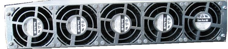
Click to zoom
Application Details
- Equipment Class
- TNB - Licensed Non-Broadcast Station Transmitter
- Date of Grant
- Oct 14, 2007
- Application Purpose
- Original Equipment
- Date of Application
- Oct 14, 2007
- Equipment Note
- UBS CDMA XMI Transceiver at 800 MHz
- Frequency Range
- 869.88000000 - 893.07000000
- Company
- Nokia Solutions and Networks
- Country
- United States
Documents & Files
Document Text
Text extracted from the exhibit documents filed with the FCC. Open a document above to read the original.
Users Manual
APPLICANT: MOTOROLA Cellular Networks FCC ID: IHET5GX1 Manuals Exhibit UBS CDMA XMI Transceiver at 800MHz 1. Installation Manual 2. Field Replaceable Units (FRU) Manual 3. ATP/Optimization Manual FCC Filing – UBS CDMA XMI Transceiver at 800MHz 1 of 1
Users Manual
APPLICANT: MOTOROLA Cellular Networks FCC ID: IHET5GX1 Installation Manual Exhibit UBS CDMA XMI Transceiver at 800MHz FCC Filing – UBS CDMA XMI Transceiver at 800MHz (cover page) R201XUBSMacroBTSHardwareInstallation 68P09283A62-3AUG2007 PRELIMINARY ©2007Motorola,Inc.AllRightsReserved Accuracy Whilereasonableeffortshavebeenmadetoassuretheaccuracyofthisdocument,Motorola,Inc.assumesno liabilityresultingfromanyinaccuraciesoromissionsinthisdocument,orfromuseoftheinformationobtained herein.Motorola,Inc.reservestherighttomakechangestoanyproductsdescribedhereintoimprovereliability, function,ordesign,andreservestherighttorevisethisdocumentandtomakechangesfromtimetotimeincontent hereofwithnoobligationtonotifyanypersonofrevisionsorchanges.Motorola,Inc.doesnotassumeanyliability arisingoutoftheapplicationoruseofanyproduct,software,orcircuitdescribedherein;neitherdoesitconvey licenseunderitspatentrightsortherightsofothers.Itispossiblethatthispublicationmaycontainreferencesto,or informationaboutMotorolaproducts(machinesandprograms),programming,orservicesthatarenotannounced inyourcountry.SuchreferencesorinformationmustnotbeconstruedtomeanthatMotorolaintendstoannounce suchMotorolaproducts,programming,orservicesinyourcountry. Copyrights Thisdocument,Motorolaproducts,and3rdPartySoftwareproductsdescribedinthisdocumentmayinclude ordescribecopyrightedMotorolaandother3rdPartysuppliedcomputerprogramsstoredinsemiconductor memoriesorothermedia.LawsintheUnitedStatesandothercountriespreserveforMotorola,itslicensors,and other3rdPartysuppliedsoftwarecertainexclusiverightsforcopyrightedmaterial,includingtheexclusiveright tocopy,reproduceinanyform,distributeandmakederivativeworksofthecopyrightedmaterial.Accordingly, anycopyrightedmaterialofMotorola,itslicensors,orthe3rdPartysoftwaresuppliedmaterialcontainedinthe Motorolaproductsdescribedinthisdocumentmaynotbecopied,reproduced,reverseengineered,distributed, mergedormodifiedinanymannerwithouttheexpresswrittenpermissionofMotorola.Furthermore,thepurchase ofMotorolaproductsshallnotbedeemedtogranteitherdirectlyorbyimplication,estoppel,orotherwise,any licenseunderthecopyrights,patentsorpatentapplicationsofMotorolaorother3rdPartysuppliedsoftware, exceptforthenormalnon-exclusive,royaltyfreelicensetousethatarisesbyoperationoflawinthesaleofa product. Alistof3rdPartysuppliedsoftwarecopyrightsarecontainedintheSupplementalinformationsectionofthis document. Restrictions Softwareanddocumentationarecopyrightedmaterials.Makingunauthorizedcopiesisprohibitedbylaw.Nopart ofthesoftwareordocumentationmaybereproduced,transmitted,transcribed,storedinaretrievalsystem,or translatedintoanylanguageorcomputerlanguage,inanyformorbyanymeans,withoutpriorwrittenpermission ofMotorola,Inc. LicenseAgreements ThesoftwaredescribedinthisdocumentisthepropertyofMotorola,Incanditslicensors.Itisfurnishedbyexpress licenseagreementonlyandmaybeusedonlyinaccordancewiththetermsofsuchanagreement. HighRiskMaterials Components,units,or3rdPartyproductsusedintheproductdescribedhereinareNOTfault-tolerantandareNOT designed,manufactured,orintendedforuseason-linecontrolequipmentinthefollowinghazardousenvironments requiringfail-safecontrols:theoperationofNuclearFacilities,AircraftNavigationorAircraftCommunication Systems,AirTrafficControl,LifeSupport,orWeaponsSystems(HighRiskActivities).Motorolaanditssupplier(s) specificallydisclaimanyexpressedorimpliedwarrantyoffitnessforsuchHighRiskActivities. Trademarks MotorolaandtheStylizedMLogoareregisteredintheUSPatent&TrademarkOffice.Allotherproductorservice namesarethepropertyoftheirrespectiveowners. TheCEmarkconfirmsMotorola,Inc.statementofcompliancewithEUdirectivesapplicabletothisproduct.Copies oftheDeclarationofComplianceandinstallationinformationinaccordancewiththerequirementsofEN50385can beobtainedfromthelocalMotorolarepresentativeorbycontactingtheCustomerNetworkResolutionCenter (CNRC).The24hourtelephonenumbersarelistedathttps://mynetworksupport.motorola.com.SelectCustomer NetworkResolutionCentercontactinformation.AlternativelyifyoudonothaveaccesstoCNRCorthe internet,contacttheLocalMotorolaOffice. PRELIMINARYAUG2007 Table of Contents Contents ■■■■■■■■■■■■■■■■■■■■■■■■■■■■■■■■■■■■■■■■■■■■■■■■■■■■■■■■■■■■■■ ■ ■ ■ ■ R201XUBSMacroBTSHardwareInstallation Revisionhistory.........................................3 Versioninformation.....................................3 ResolutionofServiceRequests...............................3 IncorporationofChangeNotices...............................3 Generalinformation.......................................4 Purpose...........................................4 Crossreferences.......................................4 Textconventions.......................................5 ContactingMotorola.......................................6 24–hoursupport.......................................6 Questionsandcomments..................................6 Errors............................................6 Securityadvice..........................................7 Warnings,cautions,andnotes..................................8 Warnings...........................................8 Cautions...........................................8 Notes............................................8 Safety..............................................9 Generalsafety........................................9 Electromagneticenergy...................................9 Caringfortheenvironment...................................10 InEUcountries.......................................10 Innon-EUcountries.....................................10 CMMlabelinganddisclosuretable...............................11 Motoroladocumentset.....................................12 OrderingdocumentsandCD-ROMs.............................12 Documentbannerdefinitions................................12 Dataencryption.......................................12 ThirdPartyComputerSoftwareandTrademarks........................13 ComputerSoftware.....................................13 Trademarks......................................…
Text truncated - open the document above for the full version.
Users Manual
Task4:RackMountingtheOptionalPSMShelfChapter2:UBSMacroBTSInstallationProcedure Task4:RackMountingtheOptionalPSMShelf ■■■■■■■■■■■■■■■■■■■■■■■■■■■■■■■■■■■■■■■■■■■■■■■■■■■■■■■■■■■■■■ ■ ■ Objectives Theobjectivesofthisprocedureareasfollows: •For-48VDCor220VACUBSonly. InstallthePSMshelftothebottomoftherack.Thesiteconfiguration/characteristicswill determineifaPSMshelfistobeinstalled. •Installtheappropriate,-48VDCor220VAC,PSMsintoPSMshelfslots1and2.For thelowcapacityframe,eithertwo-48VDCortwo220VACPSMsareinstalledinthe shelf.ThesecondPSMisforredundancy. Requireditems Thefollowingitemsarerequired: •Eithera-48VDCora220VACPSMshelf(whicheverisapplicable) •Eithertwo-48VDCortwo220VACPSMs(whicheverisapplicable) •Eight(8)M5x12mmscrewsformountingthePSMshelf-thesescrewsarepackaged withthePSMshelf •Tapemeasurewithmillimeterscale,capablemeasuringupto1200mmorwithinchscale, capablemeasuringupto48inches;formeasuringscrewlocationheightsonrack •TORXT25bitanddriver •Torquedriver Procedure Procedure2-3givestheprocedureforperformingTask4. Procedure2-3ProcedureforTask4 1 LocatethebottomRUthatistobeusedfortheinstallationofthePSMshelf. 2 Usingatapemeasure,measuremountingscrewlocationheightsoneach sideoftherack.MeasurefromthebottomoftheRUdeterminedinstep1 (RefertoFigure2-13).Markthefollowingscrewlocations: Continued 2-3268P09283A62-3 PRELIMINARYAUG2007 R201XUBSMacroBTSHardwareInstallationTask4:RackMountingtheOptionalPSMShelf Procedure2-3ProcedureforTask4(Continued) •136mm(5.35inches)forPSMshelf 3 PartiallyinsertanM5x12mmscrewintoeachlocationmarkedontherack. Leavethescrewheadsextending7mmoutfromtheracksurface. 4 RemovethePSMshelffromitspackaging. 5 AlignthekeyholeslotsinthePSMshelfwiththebottomscrews,installedin step3above(RefertoFigure2-14). 6 Insertscrewsinthe6openslotsofthePSMshelf.UsingTORXT25driver, tightenall8PSMshelfscrewsto4.77N-m(42in-lb). 7 PSMweighsapproximately5kg.Becarefulwhenhandlingthe PSMtopreventdamagetotheequipmentandpersonalinjury. InstalltheappropriatePSMsintoPSMshelfslots1and2asfollows: 1.GraspthehandleonthefrontpanelofthePSMwithonehandwhile carefullysupportingthebottomofthemodulewiththeotherhand. 2.ProperlyorientthePSMandinsertitintotheslot. 3.Slowlyslidethemoduleintotheshelfuntiltherearconnectorsare fullyseated.MakesurethatthePSMisfullyengagedwiththeshelf backplaneslotconnectors. 8 UsingaT25TORXbitandtorquedriver,tightenthePSMcaptiveretaining thumbscrewto2.37N-m(21in-lb). 68P09283A62-32-33 PRELIMINARYAUG2007 Task4:RackMountingtheOptionalPSMShelfChapter2:UBSMacroBTSInstallationProcedure Proceduralreferencediagrams ThefollowingdiagramshelpclarifycertainstepsinProcedure2-3. Figure2-13HangerscrewlayoutfortheoptionalPSMshelf 136 Hanger Screw Layout for optional PSM Shelf Hanger Screw (Detail A) NOTE 1. All dimensions are in millimeters 2. 1800 mm high rack shown. Dimension and hanger screw locations are also applicable for the 1400 mm rack. ti-cdma-06011.eps Detail A Hanger Screw Extension 7 2-3468P09283A62-3 PRELIMINARYAUG2007 R201XUBSMacroBTSHardwareInstallationTask4:RackMountingtheOptionalPSMShelf Figure2-14HangingthePSMshelf ti-cdma-05869.eps PSM shelf keyhole located on hanger screw NOTE 1. A keyhole/hanger screw is located on both the right and left sides. Both keyholes/hanger screws should be engaged at the same time. 68P09283A62-32-35 PRELIMINARYAUG2007 Task5:RackMountingforLow-CapacityFrameChapter2:UBSMacroBTSInstallationProcedure Task5:RackMountingforLow-CapacityFrame ■■■■■■■■■■■■■■■■■■■■■■■■■■■■■■■■■■■■■■■■■■■■■■■■■■■■■■■■■■■■■■ ■ ■ Objective TheobjectiveofTask5istoinstalltheUBSMacrocarrierstripassemblyintoanEIA19-inch rack. TheUBSMacrocarrierstripassemblycontainsalloftheequipmentrequiredforconfiguringa low-capacity,+27VDCstarterframe.Thelayoutoftheequipmentonthecarrierstripsallows capacityexpansionoftheframe. ThemostcommonandpreferredmethodistoinstalltheUBSMacrocarrierstripassemblyinto an1800mmor1400mmhighrack.Thismethodrequiresthattherebe600mmofclearanceon theleftandrightsidesoftherack. TheUBSMacrocarrierstripassemblyrequiresaminimumof27RackUnits(RUs)of continuousspace. Requireditems Thefollowingitemsarerequired: •UBSMacrocarrierstripassembly •Tapemeasurewithmillimeterscale,capablemeasuringupto1200mmorwithinchscale, capablemeasuringupto48inches;formeasuringscrewlocationheightsonrack •Twenty-six(26)M5x12mmscrewsformountingtheUBScarrierstripassembly-these screwsareincludedintheSTGN4034InstallationKitthatispackagedwiththeUBSMacro carrierstripassembly •TORXT25bitanddriver •Torquedriver •10mmsocketandratchet 2-3668P09283A62-3 PRELIMINARYAUG2007 R201XUBSMacroBTSHardwareInstallationTask5:RackMountingforLow-CapacityFrame Procedure Procedure2-4givestheprocedureforperformingTask5. Procedure2-4RackMountingtheLow-Capacity,+27VDCUBSMacroBTSAssembly 1 Usingatapemeasure,measuremountinghangerscrewlocationheightson eachsideoftherack(seeFigure2-15HangerscrewlayoutforUBSMacro carrierstripassemblyonpage2-39).Measuredownfromtheverytopofthe rack.Markthefollowingscrewlocations: •95.25mm(3.75inches)forthetopoftheUBSMacrocarrierstrip assembly 2 PartiallyinsertanM5x12mmscrewintoeachlocationmarkedontherack. Leavethescrewheadsextending7mmoutfromtheracksurface. 3 MovethepalletwiththeunpackedUBSMacrocarrierstripassemblyand supportneartheracksoastoallowmovementonbothsidesofthesupport andinfrontoftherack.Leavethecarrierstripassemblyonthesupport. 4 ThecarrierstripsallowfourpeopletocarefullylifttheUBSMacro carrierstripassemblyoffthesupportandontotherack.The assemblycanalsobeliftedviasomemechanicalaid(hoist,etc.) attachedtotheliftingloopsontheendsofthecarrierstrips. Fourpeople,twooneachside,areneededtoliftthecarrierstrip assembly. LifttheUBSMacrocarrierstripassemblyupandoffofthesupportandhang itontherack(seeFigure2-16Liftingandhangingthecarrierstripassembly ontherackonpage2-40). 5 Usingthecarrierstriphangerscrewspreviouslyinstalledintherack,align thetopcarrierstripkeyholeslotswiththetwohangerscrews.Hangthe carrierstripassemblyonthesetwoscrews. 6 Insertascrewinthetwobottomcarrierstripkeyholeslots(seeFigure2-17 Carrierstripa…
Text truncated - open the document above for the full version.
Users Manual
APPLICANT: MOTOROLA Cellular Networks FCC ID: IHET5GX1 FRU Manual Exhibit UBS CDMA XMI Transceiver at 800MHz FCC Filing – UBS CDMA XMI Transceiver at 800MHz (cover page) 1XUBSMacroBTSFRU 68P09283A64-3SEP2007 FOA ©2007Motorola,Inc.AllRightsReserved Accuracy Whilereasonableeffortshavebeenmadetoassuretheaccuracyofthisdocument,Motorola,Inc.assumesno liabilityresultingfromanyinaccuraciesoromissionsinthisdocument,orfromuseoftheinformationobtained herein.Motorola,Inc.reservestherighttomakechangestoanyproductsdescribedhereintoimprovereliability, function,ordesign,andreservestherighttorevisethisdocumentandtomakechangesfromtimetotimeincontent hereofwithnoobligationtonotifyanypersonofrevisionsorchanges.Motorola,Inc.doesnotassumeanyliability arisingoutoftheapplicationoruseofanyproduct,software,orcircuitdescribedherein;neitherdoesitconvey licenseunderitspatentrightsortherightsofothers.Itispossiblethatthispublicationmaycontainreferencesto,or informationaboutMotorolaproducts(machinesandprograms),programming,orservicesthatarenotannounced inyourcountry.SuchreferencesorinformationmustnotbeconstruedtomeanthatMotorolaintendstoannounce suchMotorolaproducts,programming,orservicesinyourcountry. Copyrights Thisdocument,Motorolaproducts,and3rdPartySoftwareproductsdescribedinthisdocumentmayinclude ordescribecopyrightedMotorolaandother3rdPartysuppliedcomputerprogramsstoredinsemiconductor memoriesorothermedia.LawsintheUnitedStatesandothercountriespreserveforMotorola,itslicensors,and other3rdPartysuppliedsoftwarecertainexclusiverightsforcopyrightedmaterial,includingtheexclusiveright tocopy,reproduceinanyform,distributeandmakederivativeworksofthecopyrightedmaterial.Accordingly, anycopyrightedmaterialofMotorola,itslicensors,orthe3rdPartysoftwaresuppliedmaterialcontainedinthe Motorolaproductsdescribedinthisdocumentmaynotbecopied,reproduced,reverseengineered,distributed, mergedormodifiedinanymannerwithouttheexpresswrittenpermissionofMotorola.Furthermore,thepurchase ofMotorolaproductsshallnotbedeemedtogranteitherdirectlyorbyimplication,estoppel,orotherwise,any licenseunderthecopyrights,patentsorpatentapplicationsofMotorolaorother3rdPartysuppliedsoftware, exceptforthenormalnon-exclusive,royaltyfreelicensetousethatarisesbyoperationoflawinthesaleofa product. Alistof3rdPartysuppliedsoftwarecopyrightsarecontainedintheSupplementalinformationsectionofthis document. Restrictions Softwareanddocumentationarecopyrightedmaterials.Makingunauthorizedcopiesisprohibitedbylaw.Nopart ofthesoftwareordocumentationmaybereproduced,transmitted,transcribed,storedinaretrievalsystem,or translatedintoanylanguageorcomputerlanguage,inanyformorbyanymeans,withoutpriorwrittenpermission ofMotorola,Inc. LicenseAgreements ThesoftwaredescribedinthisdocumentisthepropertyofMotorola,Incanditslicensors.Itisfurnishedbyexpress licenseagreementonlyandmaybeusedonlyinaccordancewiththetermsofsuchanagreement. HighRiskMaterials Components,units,or3rdPartyproductsusedintheproductdescribedhereinareNOTfault-tolerantandareNOT designed,manufactured,orintendedforuseason-linecontrolequipmentinthefollowinghazardousenvironments requiringfail-safecontrols:theoperationofNuclearFacilities,AircraftNavigationorAircraftCommunication Systems,AirTrafficControl,LifeSupport,orWeaponsSystems(HighRiskActivities).Motorolaanditssupplier(s) specificallydisclaimanyexpressedorimpliedwarrantyoffitnessforsuchHighRiskActivities. Trademarks MotorolaandtheStylizedMLogoareregisteredintheUSPatent&TrademarkOffice.Allotherproductorservice namesarethepropertyoftheirrespectiveowners. TheCEmarkconfirmsMotorola,Inc.statementofcompliancewithEUdirectivesapplicabletothisproduct.Copies oftheDeclarationofComplianceandinstallationinformationinaccordancewiththerequirementsofEN50385can beobtainedfromthelocalMotorolarepresentativeorbycontactingtheCustomerNetworkResolutionCenter (CNRC).The24hourtelephonenumbersarelistedathttps://mynetworksupport.motorola.com.SelectCustomer NetworkResolutionCentercontactinformation.AlternativelyifyoudonothaveaccesstoCNRCorthe internet,contacttheLocalMotorolaOffice. FOASEP2007 Table of Contents Contents ■■■■■■■■■■■■■■■■■■■■■■■■■■■■■■■■■■■■■■■■■■■■■■■■■■■■■■■■■■■■■■ ■ ■ ■ ■ 1XUBSMacroBTSFRU Revisionhistory.........................................2 Versioninformation.....................................2 ResolutionofServiceRequests...............................2 IncorporationofChangeNotices...............................2 Generalinformation.......................................3 Purpose...........................................3 Crossreferences.......................................3 Textconventions.......................................4 ContactingMotorola.......................................5 24–hoursupport.......................................5 Questionsandcomments..................................5 Errors............................................5 Securityadvice..........................................6 Warnings,cautions,andnotes..................................7 Warnings...........................................7 Cautions...........................................7 Notes............................................7 Safety..............................................8 Generalsafety........................................8 Electromagneticenergy...................................8 Caringfortheenvironment...................................9 InEUcountries.......................................9 Innon-EUcountries.....................................9 CMMlabelinganddisclosuretable...............................10 Motoroladocumentset.....................................11 OrderingdocumentsandCD-ROMs.............................11 Documentbannerdefinitions................................11 Dataencryption.......................................11 ThirdPartyComputerSoftwareandTrademarks........................12 ComputerSoftware.....................................12 Trademarks.........................................12 FCCRequirements........................................13 Cont…
Text truncated - open the document above for the full version.
Users Manual
RXSplitterEquipmentIdenticationChapter1:Overview RXSplitterEquipmentIdentication ■■■■■■■■■■■■■■■■■■■■■■■■■■■■■■■■■■■■■■■■■■■■■■■■■■■■■■■■■■■■■■ ■ ■ RXSplitterI/OPanel Figure1-14showsthewideband(800MHz-to-2.1GHz)RXsplitterI/Opanel. Figure1-14RXsplitterfrontpaneldetail WIDE BAND RX SPLITTER ti-cdma-06110.eps Mounting Tab Mounting Tab EXP OUT (RX MAIN) EXPANSION/ 3RD PARTY (Signal source via splitter: RX MAIN is XMI 1 and RX DIV is XMI 2.) NOTES: 1. All RX splitter connectors are ganged mini-coaxial. 2. RX EXP IN signal flow direction is from XMI. RX EXP OUT signal flow direction is to XMI. 3. Used in both 1.9 GHz and 800 MHz multi-XMI applications. EXP IN (RX DIV ) Future - XMI 3 EXP OUT (RX MAIN & DIV) Future - XMI 4 EXP OUT (RX MAIN & DIV) XMI 1 EXP IN (RX MAIN) EXP OUT (RX DIV ) XMI 2 WIDE BAND SPLITTER 1-4468P09283A64-3 FOASEP2007 1XUBSMacroBTSFRUPowerSupplyModule(PSM)ShelfEquipmentIdentication PowerSupplyModule(PSM)ShelfEquipment Identication ■■■■■■■■■■■■■■■■■■■■■■■■■■■■■■■■■■■■■■■■■■■■■■■■■■■■■■■■■■■■■■ ■ ■ PSMI/OPanels Figure1-15showsI/OconnectorsandPSMslotlocationsonthefrontpaneloftheUBSMacro BTS–48VDCand220VACPSMshelves.Thisfigurealsobrieflydescribesconnectorusage. APSMwillbeusedinPSM3slotwhenmore+27VDCoutputpowerisneededtosupport additionalequipment. Figure1-16showsI/OcableandconnectorlocationsontherearpaneloftheUBSMacroBTS —48VDCPSMshelf.Thisfigurealsobrieflydescribescableandconnectorusage. Figure1-17showsI/Ocable,connectorandterminallocationsontherearpaneloftheUBS MacroBTS220VACPSMshelf.Thisfigurealsobrieflydescribescableandconnectorusage. 68P09283A64-31-45 FOASEP2007 PowerSupplyModule(PSM)ShelfEquipmentIdenticationChapter1:Overview Figure1-15–48VDCand220VACPSMshelvesfrontpaneldetail ti-cdma-05915.eps Rack Mounting Flange PSM SHELF (9-pin sub-D Connector) NOTE 1 AC or -48 V DC PSM Shelf (front view) Rack Mounting Flange ALARM & CONTROL (50-pin Connector) NOTE 2 Connects to ALARM & CONTROL Connector on SSI PSM 1PSM 2 PSM 3 Empty Slot with Blank Filler Panel NOTES: 1. The PSM SHELF connector is only used when the UBS Macro frame is equipped with two optional AC or -48 V DC PSM shelves. In this case, the PSM SHELF connectors on the two PSM shelves are interconnected. 2. The ALARM & CONTROL connector connects to ALARM & CONTROL connector on the SSI. If the UBS Macro frame is equipped with two optional AC or -48 V DC PSM shelves, only one shelf has this connector cabled. PSM Captive Retaining Thumbscrew Filler Panel Captive Retaining Thumbscrew PSM Handle PSM Handle 1-4668P09283A64-3 FOASEP2007 1XUBSMacroBTSFRUPowerSupplyModule(PSM)ShelfEquipmentIdentication Figure1-16–48VDCPSMshelfrearpaneldetail _ -48 VDC 0 VD C _ 0 VDC + 2 7 V D C HAZARD OF ELECTRICAL SHOCK WITH COVERS REMOVED ti-cdma-05916.eps +27 V DC Output Power Cable (shown cut away) To PDU -48 VDC Input Power Connector (Blue) 68P09283A64-31-47 FOASEP2007 PowerSupplyModule(PSM)ShelfEquipmentIdenticationChapter1:Overview Figure1-17220VACPSMshelfrearpaneldetail ti-cdma-05917.eps +27 V DC Output Power Connector (Orange) Note 2 AC Input Terminal Block Protective Cover NOTES: 1. Equipment shown is typical. The actual equipment appearance may vary slightly. 2. The +27 V DC Output connector may be connected to back-up batteries, but usage is optional. +27 V DC Output Power Cable (shown cut away) To PDU _ 0 VDC + 27 VDC HAZARD OF ELECTRICAL SHOCK WITH COVERS REMOVED _ 0 VDC + 27 VDC HAZARD OF ELECTRICAL SHOCK WITH COVERS REMOVED 1-4868P09283A64-3 FOASEP2007 1XUBSMacroBTSFRUOptionalRGPSHeadEquipmentIdentication OptionalRGPSHeadEquipmentIdentication ■■■■■■■■■■■■■■■■■■■■■■■■■■■■■■■■■■■■■■■■■■■■■■■■■■■■■■■■■■■■■■ ■ ■ TheinformationinthissectionofthemanualwillaidinidentifyingtheoptionalRGPShead equipment. AnyofthefollowingRGPSheadsmaybeusedwiththeUBSMacroBTS: •STLN6594(Motorolapartnumber) •0186012H04(Motorolapartnumber) TheSTLN6594RGPSheadisrecommendedandshipswiththeUBSMacroBTSwhenthe optionalRGPSheadisordered. The0186012H04RGPSheadisanalternateandmaybeinuseinthefieldasareplacement spare. MotorolarecommendsthattheSTLN6594RGPSheadbeusedasareplacementspare. RGPSHeadMountingMethod TheRGPSheadismountedoutdoorsonapole.Thepoleistypicallymountedtoawall.See Figure1-18fordetails. 68P09283A64-31-49 FOASEP2007 OptionalRGPSHeadEquipmentIdenticationChapter1:Overview Figure1-18RGPSHeadMountingDetails Based on: ti-cdma-05740.eps WALL MOUNTING BRACKETS (2) CLAMP BRACKETS (2) U-BOLTS CABLE TO LIGHTNING ARRESTOR RGPS HEAD WITH 12 PIN MALE CONNECTOR MATING CONNECTORS RGPS INTERFACE CABLE WITH 12 PIN FEMALE CONNECTOR ON ONE END AND UNTERMINATED WIRE ON OTHER END CABLE TO LIGHTNING ARRESTOR ALTERNATE RGPS HEAD (MOTOROLA P/N 0186012H04) RGPS HEAD (MOTOROLA P/N STLN6594) RGPSHeadDetails TheSTLN6594and0186012H04RGPSheadshavesimilarconnectorsandthreadedpole mountadapters,buttheimplementationandlocationoftheseitemsvariesbetweenthetwo heads(seeFigure1-19). 1-5068P09283A64-3 FOASEP2007 1XUBSMacroBTSFRUOptionalRGPSHeadEquipmentIdentication Figure1-19RGPSHeadEquipment ti-cdma-05702.eps THREADED MOUNT ADAPTER THREADED MOUNT ADAPTER 12-PIN DEUTSCH TYPE MMP CONNECTOR 12-PIN DEUTSCH TYPE MMP CONNECTOR ALTERNATE RGPS HEAD (MOTOROLA P/N 0186012H04) RGPS HEAD (MOTOROLA P/N STLN6594) 68P09283A64-31-51 SEP2007FOA OptionalRGPSHeadEquipmentIdenticationChapter1:Overview 1-5268P09283A64-3 FOASEP2007 Chapter 2 ReferenceProceduresPerformedAtBTSSite ■■■■■■■■■■■■■■■■■■■■■■■■■■■■■■■■■■■■■■■■■■■■■■■■■■■■■■■■■■■■■■ ■ ■ ■ ■ 68P09283A64-32-1 SEP2007FOA ReferenceProceduresPerformedatBTSSiteChapter2:ReferenceProceduresPerformedAtBTSSite ReferenceProceduresPerformedatBTSSite ■■■■■■■■■■■■■■■■■■■■■■■■■■■■■■■■■■■■■■■■■■■■■■■■■■■■■■■■■■■■■■ ■ ■ Introduction TheproceduresinthischapterarereferencedduringvariousFRUreplacementprocedures andareperformedbythetechnicianattheBTSsite.Thesereferenceproceduresincludethe following: •Framepowerdownandpower-upsequence 2-268P09283A64-3 FOASEP2007 1XUBSMacroBTSFRUFramePowerDown&Power-UpProcedures FramePowerDown&Power-UpProcedures ■■■■■■■■■■■■■■■■■■■…
Text truncated - open the document above for the full version.
Users Manual
XMI(TransceiverModuleInternal)ModuleChapter7:XMIReplacementProcedures Figure7-3TwoPeopleProperlyCarryinganXMI(removableXMIhandleattached) ti-cdma-05891.eps 7-1868P09283A64-3 FOASEP2007 1XUBSMacroBTSFRUXMI(TransceiverModuleInternal)Module XMIInstallationProcedure FollowthestepsinProcedure7-2toinstalltheXMI. Procedure7-2XMIInstallationProcedure ATTHEBTSSITE TheXMImoduleisheavy.Twopeoplearerequiredtolift,carry,orhandlethe XMImodule. •BesuretheremovableXMIhandleisattachedtothefrontoftheXMIbefore physicallyhandlingthemodule. •Besuretwopeopleusebothhandsandwearprotectivefootwearwhen handlingtheXMI. •Besuretousetwopeopletosupportthemodulewhileslidingthemodule outoforintotheshelfslot. AnXMImodulethatisnotinashelfshouldalwaysbesetonitssideandneveron itsedge.ThiswillpreventtheXMImodulefromtippingoverandcausingdamage orinjury. 1 ThereplacementXMImoduleshouldalreadyhavetheremovalhandleattached. Ifhandleisnotattached,gotostep2. Ifhandleisattached,gotostep3. 2 AttachtheremovableXMIhandletothefrontofthereplacementXMImodule(seeFigure1-9 800MHzXMIModuleFrontPanelI/ODetailonpage1-38orFigure1-101.9GHzXMI ModuleFrontPanelI/ODetailonpage1-39forlocationofXMIhandlemountingscrew holes)asfollows: •AlignhandlescrewholeswithhandlemountingscrewholesontheXMIfrontpanel. (Notehandleorientation;handleisnotsymmetrical.) •InserttwoM5screws. •UsingaT25TORXdriver,tightenthescrewsto3.2-3.6N-m(28-32in-lb). Continued 68P09283A64-37-19 FOASEP2007 XMI(TransceiverModuleInternal)ModuleChapter7:XMIReplacementProcedures Procedure7-2XMIInstallationProcedure(Continued) 3 Thissteprequirestwopeople.Performthefollowing: •(SeeFigure7-3TwoPeopleProperlyCarryinganXMI(removableXMIhandleattached) onpage7-18.)OnepersongrasptheXMIbythehandlewithbothhands.Thesecond persongrasptheXMIfantraysideswithbothhands.Usingsafeliftingtechnique(i.e. liftwithyourlegsnotyourback),Uselegstolift(Donotuseyourback)pickuptheXMI andcarryitovertothefrontoftheframe. •(SeeFigure7-2TwoPeopleProperlyRemoving/InstallinganXMI(removableXMI handleattached)onpage7-17.)WhileonepersonholdstheXMIbythehandlewith bothhands,thesecondpersonsupportsthebottomofthemodulewithonehandandthe topofthemodulewiththeotherhand.LifttheXMIintotheappropriateslotrailsand gentlyslideitallofthewayintotheshelfslot. 4 InsertthefourXMImountingscrews;twoscrewsateachofthetopandbottommountingtabs onthefrontofthemodule.UsingaT25TORXdriver,tightenthescrewsto4.77N-m(42in-lb). 5 Ifdesired,removethehandlefromthefrontofthereplacementXMImoduleasfollows: •UsingaT25TORXdriver,removethetwoscrewsthatsecurethehandletotheXMI frontpanel. •RetainthetwoscrewswiththeXMIhandleforfutureuse. 6 For800MHzXMIonly,installtheTXDattenuator,previouslyremovedfromthefailedXMI, intotheTXDconnectoronthefrontpanelofthereplacementXMI. 7 ReconnectallcablestotheXMIfrontpanel. 8 RestorepowertotheXMIbysettingthecorrespondingXMIPDUDCcircuitbreakerto ON(pushedin). 9 ThiscompletesthephysicalinstallationoftheFRU.Ifoptimizationistobeperformedatthis time,seeOptimizationRecommendedfollowingthistable. ATTHEOMCR 10 OpenaCLIwindow.RefertoAccessingOMCRCLIwindowonpage3-3. 11 DisplaytheoverallstatusofalldevicesattheBTS,including theXMI,byenteringthefollowingcommandattheprompt: omc-000000>DISPLAYBTS-<bts#>STATUS 12 DeterminethestatusofXMI1byobservingtheBTSSTATUSreport. 13 UnlockthereplacementXMIbyenteringthefollowingcommandattheprompt: omc-000000>UNLOCKXMI-<bts#>-<xmi#>UNC 14 DisplaythestatusoftheXMIbyenteringthefollowingcommandattheprompt: omc-000000>DISPLAYBTS-<bts#>STATUS VerifythatthereplacementXMIisinanINS_ACTIVEstate. 15 FromtheOMCR,monitortheAlarmManager.Verifythatoldalarmsareclearedandno newalarmsarereported. 7-2068P09283A64-3 FOASEP2007 1XUBSMacroBTSFRUXMI(TransceiverModuleInternal)Module OptimizationRecommended PerformthefollowingBTSOptimization/ATPprocedures: •BTSDeviceDatabaseAudit •BTSDeviceDatabaseUpdate •TXPathCalibrationAudit •SpectralPurityTXMaskATP(optional) •WaveformQuality(Rho)ATP(optional) •CodeDomainPowerATP(optional) •RSSITest(FERTestisoptional) Refertothe1XUBSMacroBTSOptimization/ATPmanualfortheoptimizationprocedures. 68P09283A64-37-21 FOASEP2007 XMIFanTrayAssemblyChapter7:XMIReplacementProcedures XMIFanTrayAssembly ■■■■■■■■■■■■■■■■■■■■■■■■■■■■■■■■■■■■■■■■■■■■■■■■■■■■■■■■■■■■■■ ■ ■ XMIFanTrayAssemblyDescription TheXMIfantrayassemblyconsistsoffive27VDCfansmountedinahousing.Thishousingis theremovablerearpaneloftheXMI.(SeeFigure7-4andFigure7-5.) ThefantrayassemblymountedontherearoftheXMIdrawscoolingairinfromairventsonthe XMIfrontpanelthroughtheXMIandexhaustsairouttheXMIrearpanel. TheXMIfanhousingcontainsfivefanmountinglocations.Eachfanmountinglocationhasthe following: •built-infangrille/finger-guard •fourvibrationisolatorfanmountingposts •fanconnectorbracket Eachindividualfanhasaelectricalwiringandconnector.Theconnectormountsinthe correspondingfanconnectorbracket. TheXMIfantrayassemblyisattachedtotherearoftheXMIandsecuredwithfourscrews. WhentheXMIfantrayassemblyisattachedtotherearoftheXMI,thefivefanconnectorsmate withconnectorsontheXMIFanInterconnectBoard(FIB). TheXMIFIBprovidesaDCvoltageconnectiontoeachfaninthefantrayassemblyandisa conduitforfanspeedinformationandcontrol. TheXMIPAController(XPAC)providescentralcontrolofthethreeLPAsections.Inaddition, theXPACgathersLPAalarmsandprovidesXMIfanspeedcontrol. SystemImpact/Considerations TypicallytheXMIfantrayassemblyreplacementrequiresthattheaffectedXMIbephysically removedfromtheUBSMacroBTSframe.However,iftherearoftheframeisaccessible,theXMI fantrayassemblycanbereplacedwithoutphysicallyremovingtheaffectedXMIfromtheframe. PerformingthisreplacementprocedureonaframewithonlyoneXMIwillcauseBTS downtimeandsuspendcallprocessing. IftheframeisequippedwithonlyoneXMI,BTSservicewillbeinterruptedduringtheXMIfan trayassemblyreplacement.Iftheframeisequippedw…
Text truncated - open the document above for the full version.
Contact Information
Applicant
Steve Mitchell
Test Firm
MotorolaMelissa VanDrie
Technical Specifications
| # | Rule Parts | Frequency Range | Power Output | Emission | Tolerance |
|---|---|---|---|---|---|
| 1 | 22H | 869.88 MHz - 893.07 MHz | 26.3 W | 1M30F9W | 1.5000000000 ppm |
Other Applications from Nokia Solutions and Networks
IHET4KJ1
Apr 28, 2010LTE 700 MHz Public Safety Base Station Transceiver
Equipment Class
TNB - Licensed Non-Broadcast Station Transmitter
IHET6HG1
Sep 12, 2007CDMA Base Station
Equipment Class
PCB - PCS Licensed Transmitter
IHET7HN1
Jul 17, 20072.5 GHz Diversity Access Point
Equipment Class
TNB - Licensed Non-Broadcast Station Transmitter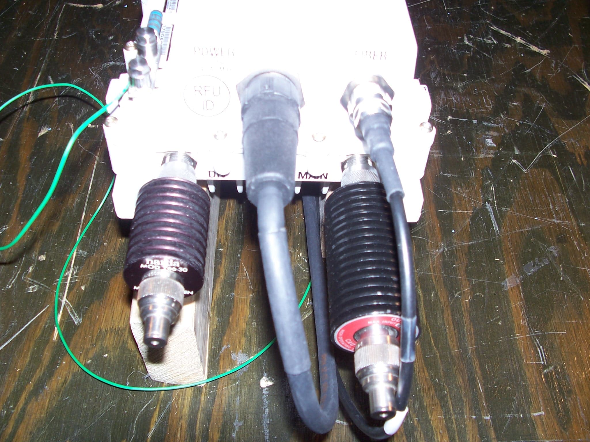
IHET7GT1
Jan 14, 20072.5GHz DIVERSITY ACCESS POINT
Equipment Class
TNB - Licensed Non-Broadcast Station Transmitter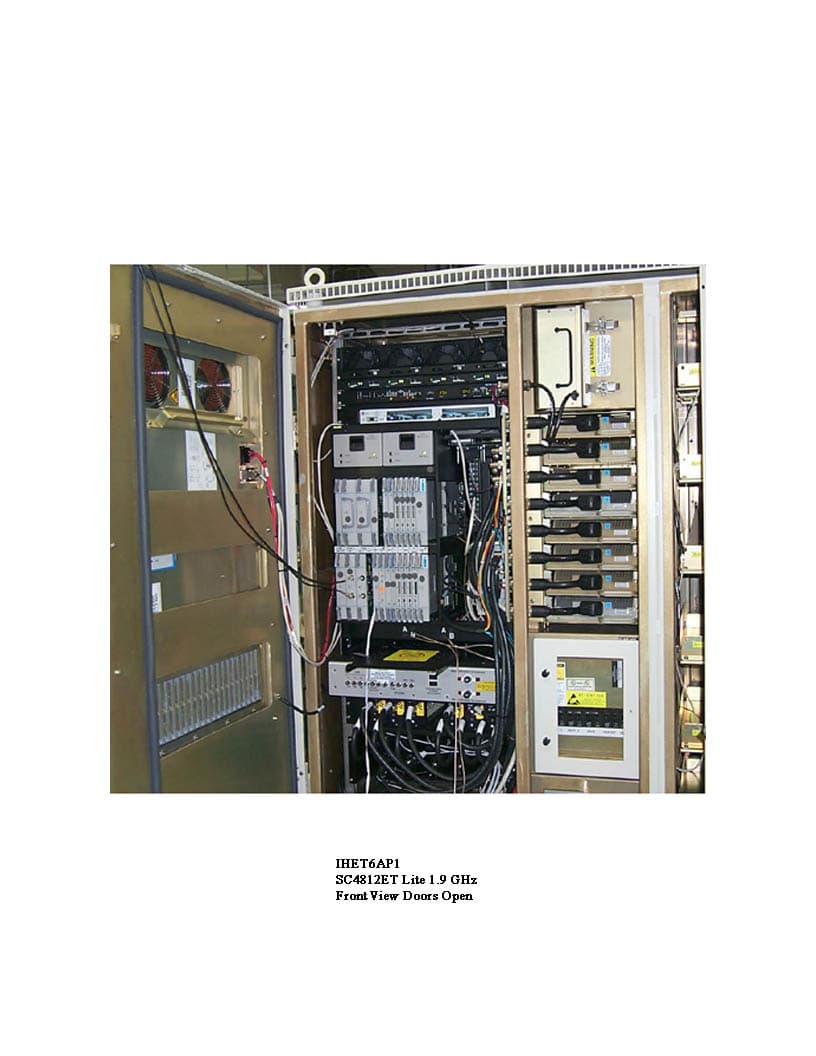
IHET6ER1
Dec 16, 2004SC4812ETLite 1.9 GHz 1X/EVDO
Equipment Class
PCB - PCS Licensed Transmitter