IHET5BR1CDMA Cellular Base Station
Nokia Solutions and Networks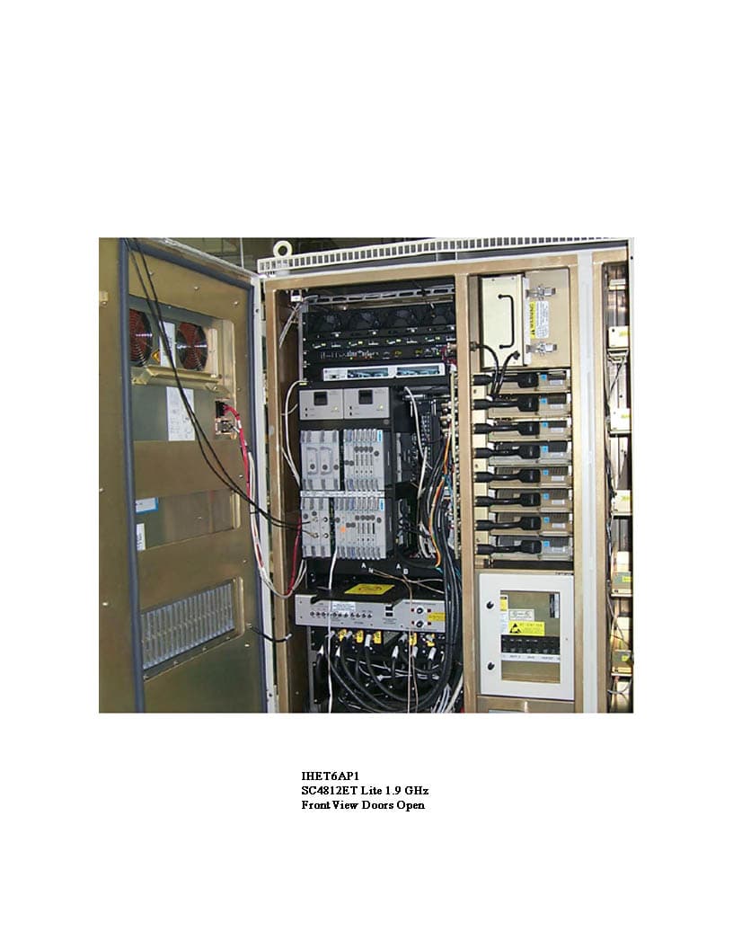
Click to zoom
Application Details
- Equipment Class
- TNB - Licensed Non-Broadcast Station Transmitter
- Date of Grant
- Sep 19, 2001
- Application Purpose
- Original Equipment
- Date of Application
- Sep 19, 2001
- Equipment Note
- CDMA Cellular Base Station
- Frequency Range
- 869.70000000 - 893.31000000
- Company
- Nokia Solutions and Networks
- Country
- United States
Documents & Files
Document Text
Text extracted from the exhibit documents filed with the FCC. Open a document above to read the original.
Users Manual
1X SCt4812ET Lite BTS Optimization/ATP Software Release 2.16.0.x and CDMA LMF Build 2.16.x.x 800 MHz and 1.9 GHz CDMA English 08/01/2001 68P09253A60–1 PRELIMINARY FOA Notice While reasonable efforts have been made to assure the accuracy of this document, Motorola, Inc. assumes no liability resulting from any inaccuracies or omissions in this document, or from use of the information obtained herein. The information in this document has been carefully checked and is believed to be entirely reliable. However, no responsibility is assumed for inaccuracies or omissions. Motorola, Inc. reserves the right to make changes to any products described herein and reserves the right to revise this document and to make changes from time to time in content hereof with no obligation to notify any person of revisions or changes. Motorola, Inc. does not assume any liability arising out of the application or use of any product, software, or circuit described herein; neither does it convey license under its patent rights or the rights of others. It is possible that this publication may contain references to, or information about Motorola products (machines and programs), programming, or services that are not announced in your country. Such references or information must not be construed to mean that Motorola intends to announce such Motorola products, programming, or services in your country. Copyrights This instruction manual, and the Motorola products described in this instruction manual may be, include or describe copyrighted Motorola material, such as computer programs stored in semiconductor memories or other media. Laws in the United States and other countries preserve for Motorola certain exclusive rights for copyrighted material, including the exclusive right to copy, reproduce in any form, distribute and make derivative works of the copyrighted material. Accordingly, any copyrighted Motorola material contained herein or in the Motorola products described in this instruction manual may not be copied, reproduced, distributed, merged or modified in any manner without the express written permission of Motorola. Furthermore, the purchase of Motorola products shall not be deemed to grant either directly or by implication, estoppel, or otherwise, any license under the copyrights, patents or patent applications of Motorola, as arises by operation of law in the sale of a product. Usage and Disclosure Restrictions License Agreement The software described in this document is the property of Motorola, Inc. It is furnished by express license agreement only and may be used only in accordance with the terms of such an agreement. Copyrighted Materials Software and documentation are copyrighted materials. Making unauthorized copies is prohibited by law. No part of the software or documentation may be reproduced, transmitted, transcribed, stored in a retrieval system, or translated into any language or computer language, in any form or by any means, without prior written permission of Motorola, Inc. High Risk Activities Components, units, or third–party products used in the product described herein are NOT fault–tolerant and are NOT designed, manufactured, or intended for use as on–line control equipment in the following hazardous environments requiring fail–safe controls: the operation of Nuclear Facilities, Aircraft Navigation or Aircraft Communication Systems, Air Traffic Control, Life Support, or Weapons Systems (“High Risk Activities”). Motorola and its supplier(s) specifically disclaim any expressed or implied warranty of fitness for such High Risk Activities. Trademarks and Motorola are registered trademarks of Motorola, Inc. Product and service names profiled herein are trademarks of Motorola, Inc. Other manufacturers’ products or services profiled herein may be referred to by trademarks of their respective companies. Copyright Copyright 2001 Motorola, Inc. All Rights Reserved Printed on Recyclable Paper REV012501 SPECIFICATIONS SUBJECT TO CHANGE WITHOUT NOTICE 08/01/2001 i 1X SCt4812ET Lite BTS Optimization/ATP PRELIMINARY Table of Contents 1X SCt4812ET Lite BTS Optimization/ATP Software Release 2.16.0.x and CDMA LMF Build 2.16.x.x List of Figuresiv. . . . . . . . . . . . . . . . . . . . . . . . . . . . . . . . . . . . . . . . . . . . . . . . . . . List of Tablesvii. . . . . . . . . . . . . . . . . . . . . . . . . . . . . . . . . . . . . . . . . . . . . . . . . . . Forewordxii. . . . . . . . . . . . . . . . . . . . . . . . . . . . . . . . . . . . . . . . . . . . . . . . . . . . . . . FCC Requirementsxv. . . . . . . . . . . . . . . . . . . . . . . . . . . . . . . . . . . . . . . . . . . . . . . General Safetyxviii. . . . . . . . . . . . . . . . . . . . . . . . . . . . . . . . . . . . . . . . . . . . . . . . . . . Revision Historyxx. . . . . . . . . . . . . . . . . . . . . . . . . . . . . . . . . . . . . . . . . . . . . . . . . Patent Notificationxxi. . . . . . . . . . . . . . . . . . . . . . . . . . . . . . . . . . . . . . . . . . . . . . . Chapter 1: Introduction Optimization Manual Scope and Layout1-1. . . . . . . . . . . . . . . . . . . . . . . . . . . . . . Purpose of the Optimization1-3. . . . . . . . . . . . . . . . . . . . . . . . . . . . . . . . . . . . . . . . When to Optimize1-4. . . . . . . . . . . . . . . . . . . . . . . . . . . . . . . . . . . . . . . . . . . . . . . . Required Test Equipment and Software1-5. . . . . . . . . . . . . . . . . . . . . . . . . . . . . . . Required Documents and Related Publications1-12. . . . . . . . . . . . . . . . . . . . . . . . . Terms and Abbreviations1-13. . . . . . . . . . . . . . . . . . . . . . . . . . . . . . . . . . . . . . . . . . BTS Equipment Identification1-15. . . . . . . . . . . . . . . . . . . . . . . . . . . . . . . . . . . . . . Cabinet Identification1-17. . . . . . . . . . . . . . . . . . . . . . . . . . . . . . . . . . . . . . . . . . . . . Internal Assembly Location and Identification1-18. . . . . . . . . . . . . . . . . . . . . . . . . BTS S…
Text truncated - open the document above for the full version.
Users Manual
Optimization/Calibration – Introduction – continued 08/01/2001 3-3 1X SCt4812ET Lite BTS Optimization/ATP PRELIMINARY antenna feed line loss can be combined to determine the required power at the frame antenna connections. The corresponding BBX2 output level required to achieve that power level on any channel/sector can then be determined based on Bay Level Offset (BLO) data determined during the optimization process. Refer to the Figure 3-1 and the LMF Help function for additional information on the layout of the LMF directory structure (including CDF file locations and formats). NOTE The CDF is normally obtained from the CBSC on a DOS formatted diskette, or through a file transfer protocol (ftp), if the LMF computer has ftp capability. Refer to the LMF Help function, and the LMF Help function, for more information. CDF Site Equipage Verification If it has not already been done, review and verify the site equipage data in the CDF with the actual site hardware and the site engineering documentation. Use a text editor to view the CDF contents. Use extreme care not to make any changes to the CDF content while viewing the file. Changes to the CDF can cause the site to operate unreliably or render it incapable of operation. CAUTION Always wear a conductive, high impedance wrist strap while handling any circuit card/module to prevent damage by ESD. Extreme care should be taken during the removal and installation of any card/module. After removal, the card/module should be placed on a conductive surface or back into the anti–static bag in which it was shipped. CAUTION BTS System Release Software Download The System Release software (for example R2.15.x.x) being used by the Base Station System (BSS) must be successfully downloaded to the BTS processor boards before optimization can be performed. Device initialization code is normally downloaded to the processor boards from the CBSC. Device application code and data is loaded from the CDMA LMF computer terminal. 3 Preparing the LMF PRELIMINARY 1X SCt4812ET Lite BTS Optimization/ATP 08/01/2001 3-4 Overview Before optimization can be performed, the CDMA LMF must be installed and configured on a computer platform meeting Motorola–specified requirements (see Recommended Test Equipment and Software in Chapter 1). For the CDMA LMF graphics to display properly, the computer platform must be configured to display more than 256 colors. See the operating system software instructions for verifying and configuring the display settings. IMPORTANT * Software and files for installing and updating the CDMA LMF are provided on CD ROM disks. The following items must be available: SCDMA LMF Program on CD ROM SCDMA LMF Binaries on CD ROM SConfiguration Data File (CDF) for each supported BTS (on floppy disk) SCBSC File for each supported BTS (on floppy disk) The following section provides information and instructions for installing and updating CDMA LMF software and files. LMF Installation and Update Procedures First Time Installation Sequence: 1. Install Java Runtime Environment (JRE) 2. Install U/WIN K–shell emulator 3. Install LMF software 4. Install BTS Binaries 5. Install/create BTS folders NOTE Follow the procedure in Table 3-1 to: 1. Install the CDMA LMF program using the CDMA LMF CD ROM 2. Install binary files using the CDMA LMF CD ROM Table 3-1: CD ROM Installation nStepAction 1Insert the CDMA LMF CD ROM disk into your disk drive. SIf the Setup screen appears, follow the instructions displayed on the screen. SIf the Setup screen is not displayed, proceed to Step 2. 2Click on the Start button 3 Preparing the LMF – continued 08/01/2001 3-5 1X SCt4812ET Lite BTS Optimization/ATP PRELIMINARY Table 3-1: CD ROM Installation nActionStep 3Select Run. 4Enter d:\autorun in the Open box and click OK. NOTE (If applicable, replace the letter d with the correct CD ROM drive letter.) 5Follow the directions displayed in the Setup screen. Copy CBSC CDF Files to the LMF Computer Before logging on to a BTS with the CDMA LMF computer to execute optimization/ATP procedures, the correct bts-#.cdf and cbsc-#.cdf files must be obtained from the CBSC and put in a bts-# folder in the CDMA LMF computer. This requires creating versions of the CBSC CDF files on a DOS–formatted floppy diskette and using the diskette to install the CDF files on the CDMA LMF computer. When copying CDF files, comply with the following to prevent BTS login problems with the Windows LMF: SThe numbers used in the bts-#.cdf and cbsc-#.cdf filenames must correspond to the locally–assigned numbers for each BTS and its controlling CBSC. SThe generic cbsc–1.cdf file supplied with the Windows LMF will work with locally numbered BTS CDF files. Using this file will not provide a valid optimization unless the generic file is edited to replace default parameters (e.g., channel numbers) with the operational parameters used locally. IMPORTANT * The procedure in Table 3-2 lists the steps required to transfer the CDF files from the CBSC to the CDMA LMF computer. For any further information, refer to the CDMA LMF Operator’s Guide (Motorola part no. 68P64114A21) or the CDMA LMF Help screen. Table 3-2: Copying CBSC CDF Files to the LMF Computer StepAction 1Login to the CBSC workstation. 2Insert a DOS–formatted floppy diskette in the workstation drive. 3Type eject –q and press the Enter key. . . . continued on next page 3 Preparing the LMF – continued PRELIMINARY 1X SCt4812ET Lite BTS Optimization/ATP 08/01/2001 3-6 Table 3-2: Copying CBSC CDF Files to the LMF Computer StepAction 4Type mount and press the Enter key. NOTE SLook for the “floppy/no_name” message on the last line displayed. SIf the eject command was previously entered, floppy/no_name will be appended with a number. Use the explicit floppy/no_name reference displayed when performing step 7. 5Change to the directory, where the files to be copied reside, by typing cd <directoryname> (e.g., cd bts–248) and pressing the Enter key. 6Type ls and press the Enter key to di…
Text truncated - open the document above for the full version.
Users Manual
Prepare to Leave the Site – continued 08/01/2001 5-5 1X SCt4812ET Lite BTS Optimization/ATP PRELIMINARY Table 5-6: Remove LMF StepAction 6Disconnect the CDMA LMF terminal Ethernet port from the BTS frame. 7Disconnect the CDMA LMF terminal serial port, the RS–232–to–GPIB interface box, and the GPIB cables as required for equipment transport. Connecting BTS T1/E1 Spans Before leaving the site, connect any T1 or E1 span connectors removed previously to allow the LMF to control the BTS. Refer to Table 5-7 and Figure 3-7. Table 5-7: Connect T1 or E1 Spans StepAction 1Re–connect any disconnected span connectors to the Span I/O A and B boards. 2If equipped, ensure the CSU is powered on. 3Verify span status, ensuring the OMC–R/CBSC can communicate with the BTS. Before Leaving the site Be sure all requirements listed in Table 5-8 are completed before leaving the site. Table 5-8: Check Before Leaving the Site StepAction 1All battery circuit breakers (for occupied shelves) are ON (pushed in). 2Both heat exchanger circuit breakers on the DC PDA are set to ON (pushed in), and the heat exchanger blowers are running. 3The External Blower Assembly (EBA) power cable is connected, and the EBA is running. 4The MAP power switch is set to ON, and the POWER (green) LED is lighted. 5The BATT TEST switch on the MAP is set to OFF, and the BATT. TEST (amber) LED is not lighted. 6No alarm conditions are being reported to the CBSC with all frame doors closed. 5 Prepare to Leave the Site – continued PRELIMINARY 1X SCt4812ET Lite BTS Optimization/ATP 08/01/2001 5-6 Notes 5 08/01/2001 1X SCt4812ET Lite BTS Optimization/ATP PRELIMINARY Chapter 6: Basic Troubleshooting Table of Contents Basic Troubleshooting Overview6-1. . . . . . . . . . . . . . . . . . . . . . . . . . . . . . . . . . . . Overview6-1. . . . . . . . . . . . . . . . . . . . . . . . . . . . . . . . . . . . . . . . . . . . . . . . Troubleshooting: Installation6-2. . . . . . . . . . . . . . . . . . . . . . . . . . . . . . . . . . . . . . . Cannot Log into Cell-Site6-2. . . . . . . . . . . . . . . . . . . . . . . . . . . . . . . . . . . Cannot Communicate with Power Meter6-5. . . . . . . . . . . . . . . . . . . . . . . Cannot Communicate with Communications Analyzer6-6. . . . . . . . . . . . Troubleshooting: Download6-7. . . . . . . . . . . . . . . . . . . . . . . . . . . . . . . . . . . . . . . . Cannot Download DATA to Any Device (Card)6-7. . . . . . . . . . . . . . . . . . Cannot ENABLE Device6-8. . . . . . . . . . . . . . . . . . . . . . . . . . . . . . . . . . . . LPA Errors6-9. . . . . . . . . . . . . . . . . . . . . . . . . . . . . . . . . . . . . . . . . . . . . . . Troubleshooting: Calibration6-10. . . . . . . . . . . . . . . . . . . . . . . . . . . . . . . . . . . . . . . Bay Level Offset Calibration Failure6-10. . . . . . . . . . . . . . . . . . . . . . . . . . . Calibration Audit Failure6-11. . . . . . . . . . . . . . . . . . . . . . . . . . . . . . . . . . . . Basic Troubleshooting – RF Path Fault Isolation6-12. . . . . . . . . . . . . . . . . . . . . . . . Overview6-12. . . . . . . . . . . . . . . . . . . . . . . . . . . . . . . . . . . . . . . . . . . . . . . . If Every Test Fails6-12. . . . . . . . . . . . . . . . . . . . . . . . . . . . . . . . . . . . . . . . . Verify BLO Checkbox6-13. . . . . . . . . . . . . . . . . . . . . . . . . . . . . . . . . . . . . . If Faults Are Isolated6-13. . . . . . . . . . . . . . . . . . . . . . . . . . . . . . . . . . . . . . . Fault Isolation Flowchart6-13. . . . . . . . . . . . . . . . . . . . . . . . . . . . . . . . . . . . Flowchart Prerequisites6-13. . . . . . . . . . . . . . . . . . . . . . . . . . . . . . . . . . . . . TX Power Output Fault Isolation Flowchart6-14. . . . . . . . . . . . . . . . . . . . . Troubleshooting: Transmit ATP6-15. . . . . . . . . . . . . . . . . . . . . . . . . . . . . . . . . . . . . Cannot Perform Txmask Measurement6-15. . . . . . . . . . . . . . . . . . . . . . . . . Cannot Perform Rho or Pilot Time Offset Measurement6-15. . . . . . . . . . . Cannot Perform Code Domain Power and Noise Floor Measurement6-16. Cannot Perform Carrier Measurement6-16. . . . . . . . . . . . . . . . . . . . . . . . . . Troubleshooting: Receive ATP6-17. . . . . . . . . . . . . . . . . . . . . . . . . . . . . . . . . . . . . . Multi–FER Test Failure6-17. . . . . . . . . . . . . . . . . . . . . . . . . . . . . . . . . . . . . Troubleshooting: CSM Checklist6-18. . . . . . . . . . . . . . . . . . . . . . . . . . . . . . . . . . . . Problem Description6-18. . . . . . . . . . . . . . . . . . . . . . . . . . . . . . . . . . . . . . . Intermittent 19.6608 MHz Reference Clock / GPS Receiver Operation6-18 No GPS Reference Source6-18. . . . . . . . . . . . . . . . . . . . . . . . . . . . . . . . . . . Checksum Failure6-18. . . . . . . . . . . . . . . . . . . . . . . . . . . . . . . . . . . . . . . . . GPS Bad RX Message Type6-18. . . . . . . . . . . . . . . . . . . . . . . . . . . . . . . . . CSM Reference Source Configuration Error6-19. . . . . . . . . . . . . . . . . . . . . 6 Table of Contents – continued PRELIMINARY 1X SCt4812ET Lite BTS Optimization/ATP 08/01/2001 Takes Too Long for CSM to Come INS6-19. . . . . . . . . . . . . . . . . . . . . . . . SCCP Backplane Troubleshooting6-20. . . . . . . . . . . . . . . . . . . . . . . . . . . . . . . . . . . Introduction6-20. . . . . . . . . . . . . . . . . . . . . . . . . . . . . . . . . . . . . . . . . . . . . . Connector Functionality6-20. . . . . . . . . . . . . . . . . . . . . . . . . . . . . . . . . . . . SCCP Backplane Troubleshooting Procedure6-21. . . . . . . . . . . . . . . . . . . . Digital Control Problems6-21. . . . . . . . . . . . . . . . . . . . . . . . . . . . . . . . . . . . DC Power Problems6-24. . . . . . . . . . . . . . . . . . . . . . . . . . . . . . . . . . . . . . . TX and RX Signal Routing Problems6-25. . . . . . . . . . . . . . . . . . . . . . . . . . RFDS – Fault Isolation6-26. . . . . . . . . . . . . . . . . . . . . . . . . . . . . . .…
Text truncated - open the document above for the full version.
Attestation Statements
________________________________________________________________________________________________ _________ FCC Filing - SC4812ET L @ 800 MHz CDMA BTS Frame Global Telecom Solutions Sector FCC ID: IHET5BR1 STATEMENTS OF CERTIFICATION EXHIBIT
Cover Letter(s)
Global Telecom Solutions Sector August 10, 2001 Federal Communications Commission Authorization & Evaluation Division 7435 Oakland Mills Road Columbia, Maryland 21046 Re: Application for Cellular Transceiver Certification Gentlemen: Motorola Inc., 1475 W. Shure Drive, Arlington Heights, Illinois 60004, herein submits: Filing fee, Application for Equipment Authorization (FCC Form 731) and Sections, for Certification of a Cellular Transceiver, FCC ID: IHET5BR1. Motorola is also the manufacturer of this equipment. Motorola requests that the following Sections of the Schematics Exhibit be kept confidential: Section A MPC6 - Multicoupler Preselector Card Section B GLI2 - Group Line Interface Card Section C BBX 1X- Broadband Transceiver Card Section D BBX2- Broadband Transceiver Card Section E MCC 1X - Multi Channel CDMA Card Section F MCC x 24E - Multi Channel CDMA Card Section G CCD - CDMA Clock Distribution Card Section H CSM2 - Clock Synchronization Module w/GPS Section I LPA - Linear Power Amplifier Section J CIO - Combiner Input/Output Card Section K Switch Card Section L HSO - High Stability Oscillator Section M SPAN I/O Section N RGD - Remote GPS Distribution Section O LFR – Low Frequency Receiver Special Note The confidential portions have been identified as such on the Uploading Sections Form. The filing fee includes fee for a confidential filing.
External Photos
Global Telecom Solutions Sector APPLICANT: MOTOROLA TRANSCEIVER TYPE: IHET5BR1 SC4812ETL @ 800 MHz CDMA BTS EXTERNAL PHOTOS EXHIBIT List of External Photographs No. PHOTOGRAPH 1 Front View Doors Closed 2 Front View Doors Open 3 Rear View 4 Left Side View 5 Right Side View 6 Top View
ID Label/Location Info
APPLICANT: MOTOROLA FCC ID: IHET5BR1 EQUIPMENT NAMEPLATE PER CFR., Title 47, Part 2.925 Bar Coding Graphics to be black A name plate of this type, or one similar to it, will be affixed to every base station. This label is permanent, indelible, and tamper evident. || | |||| | ||| | |||||| | | ||||| ||| ||| || | | ||||||| | Model No.__________________ |||| | | ||| |||| ||||| | | | ||||| | |||| ||| || || || | | Serial No.__________________ MOTOROLA FCC ID: IHET5BR1 Complies with Part 68, FCC Rules FCC Reg. No. IHEUSA-35778-DE-E REN: 03B USOC: RJ11C 800 MHz 4812ETL IHET5BR1 Location of FCC ID Label Side FCC Label (Top of Panel)
Test Report
FCC Filing – SC4812ETL @ 800 MHz CDMA BTS Global Telecom Solutions Sector FCC ID: IHET5BR1 SECTION A Summary of RF Measurements APPLICANT: MOTOROLA TRANSCEIVER TYPE: IHET5BR1 FCC Filing – SC4812ETL @ 800MHz CDMA BTS 3 of 39 Summary of Radiated RF Measurements Worst Case Radiated RF Spur Level for SC4812ETL @ 800 MHz Radiated Data Substituted Power Spec Result TX Channel Spurious Frequency (MHz) Antenna Polarity Measured Radiated Field Strength (dBuV/M) Measured Radiated Field Strength (dBm) (Note 1) TX Antenna Terminal Voltage (dBm) (Note 2) EDRP (dBm) (Note 3) FCC Part 22 MAX LIMIT (dBm) Pass/ Fail 1013 9536.905 V 45 -50.228 -59 -49.15 -13 Pass Notes: 1. Converting dBuV/M to dBm at 3 meters: (dBuV/M) + 9.542 – 104.77 = dBm Converting dBuV/M to dBm at 10 meters: (dBuV/M) + 20 – 104.77 = dBm 2. The same horn antenna and measurement system was used for EUT scan and during substitution method. After maximizing the receive antenna and adjusting signal generator power level to measure the same emission level with the spectrum analyzer as with the EUT. Signal generator output level was recorded for each of the spurious frequencies. Test cable was then disconnected from the transmit horn and was connected to the input of the S/A measuring the voltage at the terminals of the antenna. 3. This value was obtained by converting the Equivalent Isotropic Radiated Power (EIRP) to ideal half-wave dipole reference power – (Equivalent Di-Pole Radiated Power – EDRP) per (TIA-603, 2.2.12.2(i)(m)). Terry Schwenk APPLICANT: MOTOROLA TRANSCEIVER TYPE: IHET5BR1 FCC Filing – SC4812ETL @ 800MHz CDMA BTS 4 of 39 Conducted RF Measurements SC4812ETL @ 800 MHz FCC Part 22 FCC Maximum Limit Per 47 CFR: “ = Transmitted Power (10 Log 10 (P watt )) – (43 + 10 Log 10 (P watt )) dBW “ = 10 Log 10 (P watt ) - (43 + 10 Log 10 (P watt )) dBW “ = -43 dBW “ = -13 dBm Terry Schwenk CHANNEL FREQUENCY (MHz) SPUR LEVEL MEASURED (dBμ μμ μV) SPUR LEVEL MEASURED (dBm) FCC MAX LIMIT (dBm) PASS / FAIL 777 6948.39 84.46 -22.54 -13 Pass 1013 6975.395 84.11 -22.89 -13 Pass FCC Filing – SC4812ETL @ 800 MHz CDMA BTS Global Telecom Solutions Sector FCC ID: IHET5BR1 SECTION B Modulation Characteristics Maximum Power FCC Filing – SC4812ETL @ 800 MHz CDMA BTS Global Telecom Solutions Sector FCC ID: IHET5BR1 Modulation Characteristics Minimum Power
Test Report
FCC Filing – SC4812ETL @ 800 MHz CDMA BTS Global Telecom Solutions Sector FCC ID: IHET5BR1 SECTION C Spurious & Harmonic Emissions Radiated APPLICANT: MOTOROLA TRANSCEIVER TYPE: IHET5BR1 FCC Filing – SC4812ETL @ 800MHz CDMA BTS 13 of 39 Radiated RF Measurements Worst Case Radiated RF Spur Levels for SC4812ETL @ 800 MHz Radiated Data Substituted Power Spec Result TX Channel Spurious Frequency (MHz) Antenna Polarity Measured Radiated Field Strength (dBuV/M) Measured Radiated Field Strength (dBm) (Note 1) TX Antenna Terminal Voltage (dBm) (Note 2) EDRP (dBm) (Note 3) FCC Part 22 MAX LIMIT (dBm) Pass/ Fail 777 7922.818 H 44.2 -51.028 -60.6 -52.05 -13 Pass 777 7922.818 V 44.2 -51.028 -59.3 -50.75 -13 Pass 1013 9536.905 H 45 -50.228 -59.1 -49.25 -13 Pass 1013 9536.905 V 45 -50.228 -59 -49.15 -13 Pass Notes: 1. Converting dBuV/M to dBm at 3 meters: (dBuV/M) + 9.542 – 104.77 = dBm Converting dBuV/M to dBm at 10 meters: (dBuV/M) + 20 – 104.77 = dBm 2. The same horn antenna and measurement system was used for EUT scan and during substitution method. After maximizing the receive antenna and adjusting signal generator power level to measure the same emission level with the spectrum analyzer as with the EUT. Signal generator output level was recorded for each of the spurious frequencies. Test cable was then disconnected from the transmit horn and was connected to the input of the S/A measuring the voltage at the terminals of the antenna. 3. This value was obtained by converting the Equivalent Isotropic Radiated Power (EIRP) to ideal half-wave dipole reference power – (Equivalent Di-Pole Radiated Power – EDRP) per (TIA-603, 2.2.12.2(i)(m)). Terry Schwenk FCC Filing – SC4812ETL @ 800 MHz CDMA BTS Global Telecom Solutions Sector FCC ID: IHET5BR1 SECTION D Spurious & Harmonic Emissions Conducted APPLICANT: MOTOROLA TRANSCEIVER TYPE: IHET5BR1 FCC Filing – SC4812ETL @ 800MHz CDMA BTS 15 of 39 Conducted RF Measurements SC4812ETL @ 800 MHz FCC Part 22 FCC Maximum Limit Per 47 CFR: “ = Transmitted Power (10 Log 10 (P watt )) – (43 + 10 Log 10 (P watt )) dBW “ = 10 Log 10 (P watt ) - (43 + 10 Log 10 (P watt )) dBW “ = -43 dBW “ = -13 dBm Terry Schwenk CHANNEL FREQUENCY (MHz) SPUR LEVEL MEASURED (dBμ μμ μV) SPUR LEVEL MEASURED (dBm) FCC MAX LIMIT (dBm) PASS / FAIL 777 6948.39 84.46 -22.54 -13 Pass 1013 6975.395 84.11 -22.89 -13 Pass Global Telecom Solutions Sector FCC ID: IHET5BR1 SPURIOUS & HARMONIC EMISSIONS CONDUCTED CDMA Transmitter Channel 25 Maximum Power Global Telecom Solutions Sector FCC ID: IHET5BR1 SPURIOUS & HARMONIC EMISSIONS CONDUCTED CDMA Transmitter Channel 25 Minimum Power Network Systems Group CDMA Systems Division FCC ID: IHET5BR1 SPURIOUS & HARMONIC EMISSIONS CONDUCTED CDMA Transmitter Channel 1175 Maximum Power Global Telecom Solutions Sector FCC ID: IHET5BR1 SPURIOUS & HARMONIC EMISSIONS CONDUCTED CDMA Transmitter Channel 1175 Minimum Power M FCC ID: IHET5BR1 Global Telecom Solutions Sector FCC Filing – SC4812ETL @ 800 MHz CDMA BTS 28 of 39 SECTION E OCCUPIED BANDWIDTH SC4812ETL NOTE: The BTS was configured for maximum power out of 46.0 dBm and minimum power out of 23.0 dBm respectively. The max and min output power was set to 40.0 Watts or 200 mWatts respectively using an HP437B power meter. The following formula is used to obtain the correct power reference point from which the OBW of the CDMA signal is obtained. Se example calculation below: Power (measured in 30 kHz bandwidth) / 10 log (1.2288 MHz / 30 kHz) Example: 29.88 dBm / 16.12 dB = 46.0 dBm The occupied bandwidth is measured in a 30 kHz resolution bandwidth. The summary is listed below. Francisco Avalos CHANNEL / POWER FREQUENCY (MHz) MEASURED (MHz) FCC LIMIT (MHz) Pass / Fail 1013 / MAX 869.700 1.215 1.25 Pass 777 / MAX 893.310 1.225 1.25 Pass 1013 / MIN 869.700 1.225 1.25 Pass 777 / MIN 893.310 1.225 1.25 Pass FCC Filing – SC4812ETL @ 800 MHz CDMA BTS Global Telecom Solutions Sector FCC ID: IHET5BR1 Occupied Bandwidth Maximum Power FCC Filing – SC4812ETL @ 800 MHz CDMA BTS Global Telecom Solutions Sector FCC ID: IHET5BR1 Occupied Bandwidth Minimum Power M FCC ID: IHET5BR1 Global Telecom Solutions Sector FCC Filing – SC4812ETL @ 800 MHz CDMA BTS 35 of 39 SECTION F FREQUENCY STABILITY SC4812ETL MODE 27V POWER WORST CASE ∆ PPM FCC REQUIREMENT Pass / Fail CSM1 85-115% <0.02 +/- 1.5 PPM MAX Pass CSM2 85-115% <0.02 +/- 1.5 PPM MAX Pass Terry Schwenk MODE TEMPERATURE WORST CASE ∆ PPM FCC REQUIREMENT Pass / Fail CSM1 -30º to +50º C <0.2 +/- 1.5 PPM MAX Pass CSM2 -30º to +50º C <0.2 +/- 1.5 PPM MAX Pass
Contact Information
Applicant
Steve Mitchell
Technical Contact
Underwriters Laboratories Inc.James R Marley
[email protected](919) 549-1408
12 Laboratory Drive · Research Triangle Park, North Carolina · United States
Non-Technical Contact
Underwriters Laboratories Inc.Jack W Davis
[email protected](919) 549-1447
Test Firm
UL LLCRick Titus
Technical Specifications
| # | Rule Parts | Frequency Range | Power Output | Emission | Tolerance |
|---|---|---|---|---|---|
| 1 | 22H | 869.7 MHz - 893.31 MHz | 40 W | 1M25F9W | 1.5000000000 ppm |
Other Applications from Nokia Solutions and Networks
IHET4KJ1
Apr 28, 2010LTE 700 MHz Public Safety Base Station Transceiver
Equipment Class
TNB - Licensed Non-Broadcast Station Transmitter
IHET5GX1
Oct 14, 2007UBS CDMA XMI Transceiver at 800 MHz
Equipment Class
TNB - Licensed Non-Broadcast Station Transmitter
IHET6HG1
Sep 12, 2007CDMA Base Station
Equipment Class
PCB - PCS Licensed Transmitter
IHET7HN1
Jul 17, 20072.5 GHz Diversity Access Point
Equipment Class
TNB - Licensed Non-Broadcast Station Transmitter
IHET7GT1
Jan 14, 20072.5GHz DIVERSITY ACCESS POINT
Equipment Class
TNB - Licensed Non-Broadcast Station Transmitter