IHET5DX1SC4812T-MC 1X/1X-DO @ 800 MHz CDMA BTS
Nokia Solutions and Networks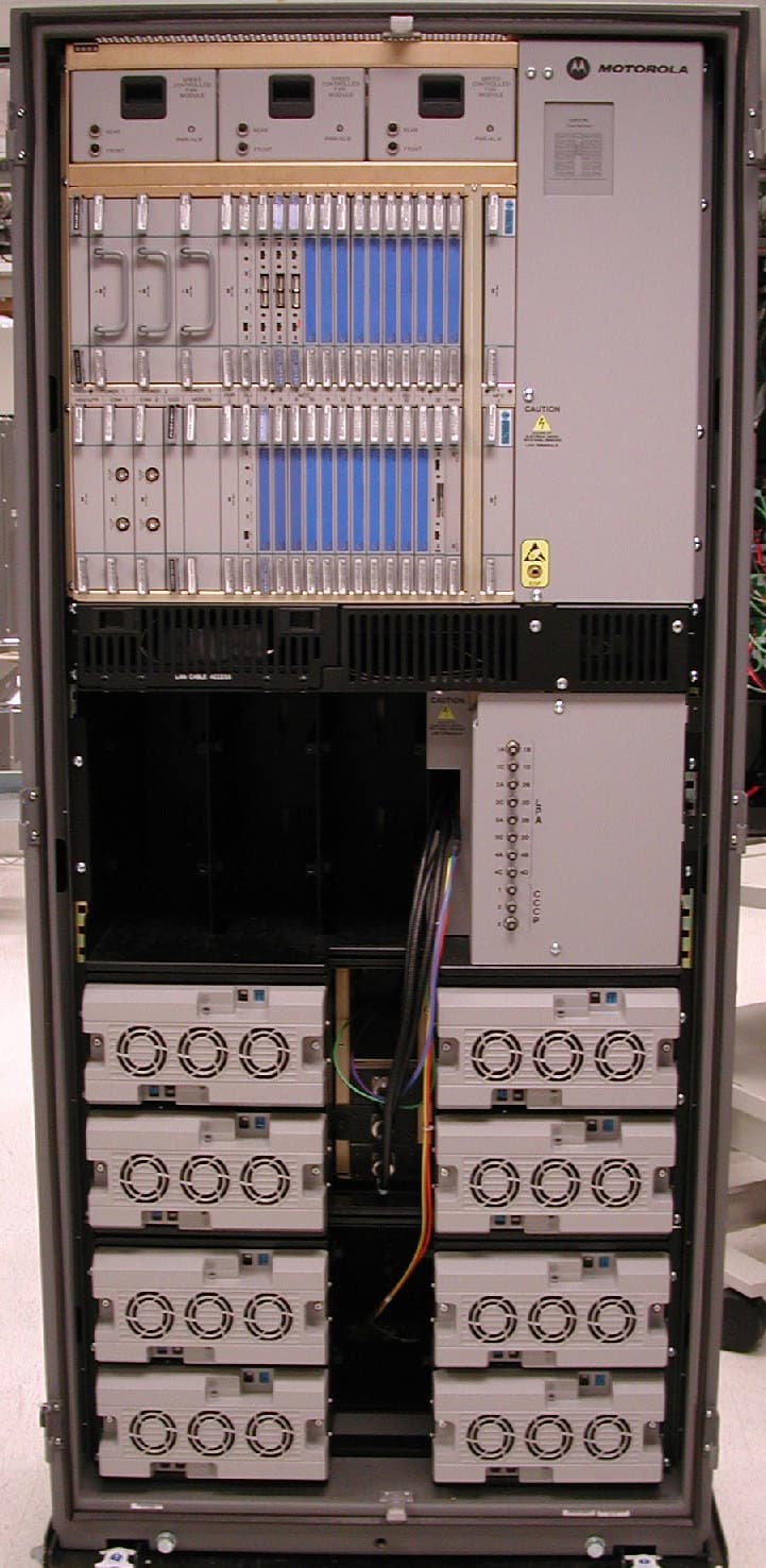
Click to zoom
Application Details
- Equipment Class
- TNB - Licensed Non-Broadcast Station Transmitter
- Date of Grant
- Apr 21, 2004
- Application Purpose
- Original Equipment
- Date of Application
- Apr 21, 2004
- Equipment Note
- SC4812T-MC 1X/1X-DO @ 800 MHz CDMA BTS
- Frequency Range
- 869.70000000 - 893.31000000
- Company
- Nokia Solutions and Networks
- Country
- United States
Documents & Files
Document Text
Text extracted from the exhibit documents filed with the FCC. Open a document above to read the original.
Users Manual
CONTROLLED INTRODUCTION 68P64115A19–4 Mar 2003 ENGLISH CDMA Software Release R2.16.1.x Technical Information 1X SC 4812T-MC BTS Hardware Installation 800 MHz CONTROLLED INTRODUCTION SPECIFICATIONS SUBJECT TO CHANGE WITHOUT NOTICE Notice While reasonable efforts have been made to assure the accuracy of this document, Motorola, Inc. assumes no liability resulting from any inaccuracies or omissions in this document, or from use of the information obtained herein. The information in this document has been carefully checked and is believed to be entirely reliable. However, no responsibility is assumed for inaccuracies or omissions. Motorola, Inc. reserves the right to make changes to any products described herein and reserves the right to revise this document and to make changes from time to time in content hereof with no obligation to notify any person of revisions or changes. Motorola, Inc. does not assume any liability arising out of the application or use of any product, software, or circuit described herein; neither does it convey license under its patent rights or the rights of others. It is possible that this publication may contain references to, or information about Motorola products (machines and programs), programming, or services that are not announced in your country. Such references or information must not be construed to mean that Motorola intends to announce such Motorola products, programming, or services in your country. Copyrights This instruction manual, and the Motorola products described in this instruction manual may be, include or describe copyrighted Motorola material, such as computer programs stored in semiconductor memories or other media. Laws in the United States and other countries preserve for Motorola certain exclusive rights for copyrighted material, including the exclusive right to copy, reproduce in any form, distribute and make derivative works of the copyrighted material. Accordingly, any copyrighted Motorola material contained herein or in the Motorola products described in this instruction manual may not be copied, reproduced, distributed, merged or modified in any manner without the express written permission of Motorola. Furthermore, the purchase of Motorola products shall not be deemed to grant either directly or by implication, estoppel, or otherwise, any license under the copyrights, patents or patent applications of Motorola, as arises by operation of law in the sale of a product. Usage and Disclosure Restrictions License Agreement The software described in this document is the property of Motorola, Inc. It is furnished by express license agreement only and may be used only in accordance with the terms of such an agreement. Copyrighted Materials Software and documentation are copyrighted materials. Making unauthorized copies is prohibited by law. No part of the software or documentation may be reproduced, transmitted, transcribed, stored in a retrieval system, or translated into any language or computer language, in any form or by any means, without prior written permission of Motorola, Inc. High Risk Activities Components, units, or third–party products used in the product described herein are NOT fault–tolerant and are NOT designed, manufactured, or intended for use as on–line control equipment in the following hazardous environments requiring fail–safe controls: the operation of Nuclear Facilities, Aircraft Navigation or Aircraft Communication Systems, Air Traffic Control, Life Support, or Weapons Systems (“High Risk Activities”). Motorola and its supplier(s) specifically disclaim any expressed or implied warranty of fitness for such High Risk Activities. CONTROLLED INTRODUCTION SPECIFICATIONS SUBJECT TO CHANGE WITHOUT NOTICE Trademarks and Motorola are registered trademarks of Motorola, Inc. Product and service names profiled herein are trademarks of Motorola, Inc. Other manufacturers’ products or services profiled herein may be referred to by trademarks of their respective companies. Copyright 2003 Motorola, Inc. Printed on Recyclable Paper REV012501 SC 4812T-MC vs SC 4812T BTS Read Me First (Comparison) 68P64115A19–4 Mar 20031X SC 4812T-MC BTS Hardware Installation - Software Release R2.16.1.x CONTROLLED INTRODUCTION RMF-1 Read Me First SC 4812T-MC vs SC 4812T BTS Read Me First (Comparison) This Read-me-first document describes a summary of changes between the existing SCt4812T BTS and the SC 4812T-MC (Multicarrier) BTS. The SC 4812T-MC is based on the existing SC 4812T platform and employs similar hardware and architecture. The differences between these products are briefly described and illustrated below. This section is not intended to replace the SC 4812T-MC manual set. Multicarrier provides the capability for all PAs in all quadrants to provide trunked power across all sector/carriers. This differs from the previous architecture in which PA modules within a quadrant provided trunked power to only one carrier. Furthermore, in SC 4812T-MC, adjacent channels can be combined onto one antenna versus being transmitted on separate antennas in SC 4812T. An overview of the BTS differences is illustrated in the following table and in illustrations on the following pages (Figure 1 thru Figure 4). SC 4812T Description#DescriptionSC 4812T-MC 1 2 3x3 DC Power Input (see Figure 1) 1 2x2 DC Power Input (see Figure 1) 1 2 7 3 I/O Plate supporting 3x3 DC Power Input (see Figure 2) 2 I/O Plate supporting 2x2 DC Power Input (see Figure 2) 3 4 CCCP Fan Tray 3 CCCP Speed Controlled Fan Tray 4 C-CCP Cage: SCIO (3- or 6-Sector) SBBX-1X SSwitch 4 C-CCP Cage: SMCIO (3- or 6-Sector) SHigh Power BBX-1X SHigh Power Switch 6 5 PA Shelves: SSC 4812T LPA S4x4 TX Backplane SPA Location and Mapping (see Figure 3) 5 PA Shelves: SSC 4812T CLPA SMulticarrier module SParallel PA Combiner SEnhanced Trunking Module SLPA/PLC Filler Panel SPA Location and Mapping (see Figure 3) 5 6 7 2:1 or 4:1 Combiners or Dual Bandpass TX Filters 6 TX Bandpass Filters and/or TX Output Termi…
Text truncated - open the document above for the full version.
Cover Letter(s)
m Global Telecom Solutions Sector M 1 of 2 Global Telecom Solutions Sector, 5555 North Beach Street TX14-7C, Fort Worth, Texas Telephone (817) 245-6039, Fax (817) 245-6248, Email [email protected] April 14, 2004 Federal Communications Commission Authorization & Evaluation Division 7435 Oakland Mills Road Columbia, Maryland 21046 Re: Application for Cellular Transceiver Certification Gentlemen: Motorola Inc., 5555 North Beach Street, Fort Worth, Texas 76137, herein submits: Application for Equipment Authorization (FCC Form 731) and Sections, for Certification of a Cellular Transceiver, FCC ID: IHET5DX1. Motorola is also the manufacturer of this equipment. Motorola requests that the Descriptive Information, Internal Photos, Parts List, and the following Sections of the Schematics Exhibit be kept confidential: HP BBX1X- Hi Power Broadband Transceiver Card CCD - CDMA Clock Distribution Card CIO - Combiner Input/Output Card CSM1 - Clock Synchronization Module w/GPS CSM2- Clock Synchronization Module w/GPS GLI2 - Group Line Interface Card GLI3 – Group Line Interface Card HSO - High Stability Oscillator LFR – Low Frequency Receiver (Special Vendor Note) CLPA – Linear Power Amplifier MCC1X - Multi Channel CDMA Card MCC1X-DO - Multi Channel CDMA Card MPC3 - Multicoupler Preselector Card RGD – Remote GPS Distribution Card PAC – Power Alarm Card PSM – Power Supply Module SITE I/O – Site Input Output SPAN I/O – Spanline Input Output HP SW – Hi Power Switchboard
External Photos
m Global Telecom Solutions Sector SC4812T-MC 1X/1X-EVDO @ 800 MHz CDMA BTS FCC ID: IHET5DX1 External Photo Exhibit M 4/14/2004 9:18 AM Global Telecom Solutions Sector, 5555 North Beach Street TX14-7C, Fort Worth, Texas Telephone (817) 245-6039, Fax (817) 245-6248, Email [email protected] Photo Number Photograph Description Page 1 Front View with Doors Closed 2 2 Front View with Doors Open 3 3 Rear View with Panel 4 4 Rear View without Panel 5 5 Left Side View 6 6 Right Side View 7 7 Top View 8
ID Label/Location Info
m Global Telecom Solutions Sector SC4812T-MC 1X/1X-EVDO @ 800 MHz CDMA BTS FCC ID: IHET5DX1 FCC Identification Nameplate/Frame Label Location Exhibit M 4/14/2004 9:06 AM Global Telecom Solutions Sector, 5555 North Beach Street TX14-7C, Fort Worth, Texas Telephone (817) 245-6039, Fax (817) 245-6248, Email [email protected] EQUIPMENT NAMEPLATE PER CFR., Title 47, Part 2.925 Bar Coding Graphics to be black A name plate of this type, or one similar to it, will be affixed to every base station. This label is permanent, indelible, and tamper evident. || | |||| | ||| | |||||| | | ||||| ||| ||| || | | |||||| Serial No. Complies with Part 68, FCC Rules Model No. _____________ ||||| | | ||| |||| ||||| | | | ||||| | |||| ||| || || || | | FCC Reg. No. REN: USOC: MOTOROLA FCC ID: IHET5DX1 m Global Telecom Solutions Sector SC4812T-MC 1X/1X-EVDO @ 800 MHz CDMA BTS FCC ID: IHET5DX1 FCC Label Exhibit M 4/14/2004 9:05 AM Global Telecom Solutions Sector, 5555 North Beach Street TX14-7C, Fort Worth, Texas Telephone (817) 245-6039, Fax (817) 245-6248, Email [email protected]
Operational Description
IHET5DX1 FCC Filing- SC4812T 1X / 1X-EVDO @ 800 MHz CDMA BTS 1 of 13 DESCRIPTIVE INFORMATION FCC FILING FOR SC4812T-MC 1X / 1X-EVDO @ 800 MHz CDMA BTS The Information in this exhibit is in accordance with the FCC Rules and Regulations, Vol. II, Part 2, Subpart J. Sections 2.1033 through 2.1055 are addressed. Section 2.1033 (a) Name of Applicant and Manufacturer: MOTOROLA Section 2. 1033 (b) Identification of Equipment: IHET5DX1 Section 2. 1033 (c) Quantity Production: Quantity Production is planned. Section 2. 1033 (d) Technical Description This Transmitter is intended for use in the Public Cellular Radio Telecommunications Service and is designed in compliance with the FCC Rules and Regulations Title 47, Part 22(H). This transmitter is capable of spread spectrum (CDMA) operation, and allows up to 128 Walsh codes to support Pilot, Sync, Paging, Supplemental, and Traffic channels. (1) Types of Emissions This equipment will be capable of operation using wide band spread spectrum techniques employing Direct Sequence Code Division Multiple Access (DS-CDMA) digital communication techniques. For this transmitter, the emission designator is 1M30F9W (per FCC Part 2.201, subpart C). (2) Frequency Range This transmitter operates within the 869.70 to 893.31 MHz Band for 1X operation, and within the 869.76 to 893.25 MHz Band for 1X-EVDO operation. (per FCC Part 22). This base station will support CDMA operations on channel numbers 1013 through 1023 and 1 through 777 inclusive for 1X operation, and channel numbers 1015 through 1023 and 1 through 775 inclusive for 1X-EVDO operation (3) Range of Operating Power The rated maximum average power out of the SC4812T-MC 1X / 1X-EVDO @ 800 MHz CDMA BTS is 120 W (50.8 dBm) per RF carrier. However, in CDMA the actual power output is based on the number of traffic channels in operation. The minimum power occurs when only a pilot signal is present. The maximum power occurs when a pilot along with synchronization, paging, and traffic IHET5DX1 FCC Filing- SC4812T 1X / 1X-EVDO @ 800 MHz CDMA BTS 2 of 13 (3) Range of Operating Power (cont.) channels are present. For a typical system setup, the theoretical difference between minimum power and maximum power is about 8 dB. The output power is variable in 0.25 dB steps. In addition, the dynamics of a CDMA system allow for what is called “cell breathing”. This allows an operator to vary the range of a cell by controlling the power of the pilot signal. (4) Maximum Power Limits The peak output power of a base station transmitter may not exceed 500 Watts as defined in Part 22.913(a). (5) Applied voltages and currents into the final transistor elements of the transmitter output: The applied voltages and currents into each of the Linear Power Amplifier’s final transistor elements are as follows: Drain 27.0 VDC Drain Current 1.0 AMPS Gate Voltage 4 VDC (6) Function of Each Active Device Refer to the Operational Description Exhibit. (7) Complete Circuit Diagrams Refer to the Schematics Exhibit. (8) Instruction/Installation Manual Refer to the Installation Manual Exhibit. (9) Tune-Up/Optimization Procedure Refer to the Users Manual Exhibit. IHET5DX1 FCC Filing- SC4812T 1X / 1X-EVDO @ 800 MHz CDMA BTS 3 of 13 (10) Means for Frequency Stabilization Refer to the Test Report Exhibit. The Clock Synchronization Module (CSM/CSM2) provides clock and time signals for an SC4812T-MC 1X/1X-EVDO @ 800 MHz CDMA BTS. In addition, it provides the primary source, a 3 MHz clock, for the transmit synthesizer in the Broadband Transceiver. The CSM/CSM2 relies on a GPS receiver, either riding piggyback onto the CSM/CSM2 card or remotely located in an integrated package with the GPS antenna as the primary time reference for the ovenized oscillator. Two types of redundancy are provided: 1) Dual CSM/CSM2 cards provide redundancy in case of primary CSM/CSM2 failure. 2) Redundancy is also provided by either a High Stability Oscillator (HSO) or a Low Frequency Reference (LFR), such as a Loran C receiver, residing in a separate slot. The HSO is provided in case of GPS system failure. The CSM/CSM2 uses the received signals as a reference to provide the required clock for the site. The CSM/CSM2 distributes CDMA time, a 19.6608 MHz clock, and a two second synchronization pulse every even second of universal time to the CDMA Clock Distribution (CCD) Cards . The CSM/CSM2 is also responsible for configuration and management of the GPS and LFR systems. CSM/CSM2 software determines on a site basis what the GPS and LFR configurations should be. For future Commercial CDMA systems, GPS and LFR configuration information could optionally be downloaded to the CSM/CSM2 from the GLI2. The CSM/CSM2 is managed by the GLI2. The High Stability Oscillator (HSO) or Low Frequency Time Reference (LFR) is used to provide a stable time reference in case of a GPS system failure or shutdown. The output of the LFR card is routed to the CSM/CSM2 cards, which derive the appropriate time references for the RF section. The current LFR is a LoranC receiver. In areas where LoranC is unavailable, the HSO may be used. IHET5DX1 FCC Filing- SC4812T 1X / 1X-EVDO @ 800 MHz CDMA BTS 4 of 13 (11) Means for Attenuation of Spurious Emissions Refer to the Test Report Exhibit. Bandpass filters are employed in the transmit RF circuit to attenuate far out spurious emissions. The filter used here is of an air dielectric cavity resonator type. In addition to the digital filters described below, the baseband also employs a discrete anti-alias filter that attenuates signals greater than 2MHz. Out of band emissions are also attenuated by ceramic filters in the transmit RF lineup. In addition, suppression of spurious radiation is obtained by proper shielding techniques. Means for Limiting Modulation Refer to the Test Report Exhibit. In a CDMA system, the input signal (voice for example) is sampled and coded in a vocoder. This signal is then spread to approximately 1.28 MHz by a pseudo-random spreading code. This…
Text truncated - open the document above for the full version.
Parts List/Tune Up Info
68P64115A21–B Sept 2003 ENGLISH CDMA Software Release R2.16.1.x Technical Information 1X SC 4812T-MC Multicarrier BTS Optimization/ATP 800 Mhz SPECIFICATIONS SUBJECT TO CHANGE WITHOUT NOTICE Notice While reasonable efforts have been made to assure the accuracy of this document, Motorola, Inc. assumes no liability resulting from any inaccuracies or omissions in this document, or from use of the information obtained herein. The information in this document has been carefully checked and is believed to be entirely reliable. However, no responsibility is assumed for inaccuracies or omissions. Motorola, Inc. reserves the right to make changes to any products described herein and reserves the right to revise this document and to make changes from time to time in content hereof with no obligation to notify any person of revisions or changes. Motorola, Inc. does not assume any liability arising out of the application or use of any product, software, or circuit described herein; neither does it convey license under its patent rights or the rights of others. It is possible that this publication may contain references to, or information about Motorola products (machines and programs), programming, or services that are not announced in your country. Such references or information must not be construed to mean that Motorola intends to announce such Motorola products, programming, or services in your country. Copyrights This instruction manual, and the Motorola products described in this instruction manual may be, include or describe copyrighted Motorola material, such as computer programs stored in semiconductor memories or other media. Laws in the United States and other countries preserve for Motorola certain exclusive rights for copyrighted material, including the exclusive right to copy, reproduce in any form, distribute and make derivative works of the copyrighted material. Accordingly, any copyrighted Motorola material contained herein or in the Motorola products described in this instruction manual may not be copied, reproduced, distributed, merged or modified in any manner without the express written permission of Motorola. Furthermore, the purchase of Motorola products shall not be deemed to grant either directly or by implication, estoppel, or otherwise, any license under the copyrights, patents or patent applications of Motorola, as arises by operation of law in the sale of a product. Usage and Disclosure Restrictions License Agreement The software described in this document is the property of Motorola, Inc. It is furnished by express license agreement only and may be used only in accordance with the terms of such an agreement. Copyrighted Materials Software and documentation are copyrighted materials. Making unauthorized copies is prohibited by law. No part of the software or documentation may be reproduced, transmitted, transcribed, stored in a retrieval system, or translated into any language or computer language, in any form or by any means, without prior written permission of Motorola, Inc. High Risk Activities Components, units, or third–party products used in the product described herein are NOT fault–tolerant and are NOT designed, manufactured, or intended for use as on–line control equipment in the following hazardous environments requiring fail–safe controls: the operation of Nuclear Facilities, Aircraft Navigation or Aircraft Communication Systems, Air Traffic Control, Life Support, or Weapons Systems (“High Risk Activities”). Motorola and its supplier(s) specifically disclaim any expressed or implied warranty of fitness for such High Risk Activities. Trademarks and Motorola are registered trademarks of Motorola, Inc. Product and service names profiled herein are trademarks of Motorola, Inc. Other manufacturers’ products or services profiled herein may be referred to by trademarks of their respective companies. © Copyright 2003 Motorola, Inc. Printed on Recyclable Paper REV012501 SC TM 4812T-MC vs SC 4812T BTS Read Me First (Comparison) 68P64115A21–B Sept 20031X SC 4812T-MC Multicarrier BTS Optimization/ATP RMF-1 Read Me First SC TM 4812T-MC vs SC 4812T BTS Read Me First (Comparison) This Read-me-first document describes a summary of changes between the existing SC 4812T BTS and the SC 4812T-MC (Multicarrier) BTS. The SC 4812T-MC is based on the existing SC 4812T platform and employs similar hardware and architecture. The differences between these products are briefly described and illustrated below. This section is not intended to replace the SC 4812T-MC manual set. This information applies generally to both +27V and –48V frames, although only +27V illustrations are shown. Multicarrier provides the capability for all PAs in all quadrants to provide trunked power across all sector/carriers. This differs from the previous architecture in which PA modules within a quadrant provided trunked power to only one carrier. Furthermore, in SC 4812T-MC, adjacent channels can be combined onto one antenna versus being transmitted on separate antennas in SC 4812T. An overview of the BTS differences is illustrated in the following table and in illustrations on the following pages (Figure 1 thru Figure 4). SC 4812T Description#DescriptionSC 4812T-MC 1 2 3x3 DC Power Input (see Figure 1) 1 2x2 DC Power Input (see Figure 1) 1 2 7 1 2 3 I/O Plate supporting 3x3 DC Power Input (see Figure 2) 2 I/O Plate supporting 2x2 DC Power Input (see Figure 2) 1 2 3 7 CCCP Fan Tray 3 CCCP Speed Controlled Fan Tray 4 C-CCP Cage: SCIO (3- or 6-Sector) SBBX-1X SSwitch 4 C-CCP Cage: SMCIO (3- or 6-Sector) SHigh Power BBX-1X SHigh Power Switch 4 6 5 PA Shelves: SSC 4812T LPA S4x4 TX Backplane SPA Location and Mapping (see Figure 3) SShelf Qty: 1 for up to 2 carriers; 2 for 3 or more carriers. 5 PA Shelves: SSC 4812T CLPA SMulticarrier module S(Switched) Parallel Linear amplifier Combiner SEnhanced Trunking Module SLPA/PLC Filler Panel SPA Location and Mapping (see Figure 3) SShelf Qty: 2 for all configurations 5 6 7…
Text truncated - open the document above for the full version.
Parts List/Tune Up Info
Initial Power–up Tests and Procedures 68P64115A21–B Sept 2003 1X SC 4812T-MC Multicarrier BTS Optimization/ATP 2-12 Notes 2 Sept 2003 1X SC 4812T-MC Multicarrier BTS Optimization/ATP 3-1 Chapter 3 Optimization/Calibration 3 Introduction to Optimization and Calibration 68P64115A21–B Sept 2003 1X SC 4812T-MC Multicarrier BTS Optimization/ATP 3-2 Introduction to Optimization and Calibration Overview This section describes procedures for isolating the BTS from the span lines, preparing and using the LMF, downloading system operating software, CSM reference verification/optimization, set up and calibration of the supported test equipment, transmit/receive path verification, and verifying the customer defined alarms and relay contacts are functioning properly. NOTE Before using the LMF, use an editor to view the “CAVEATS” section in the “readme.txt” file in the c:\wlmf folder for any applicable information. Optimization Process Summary After a BTS is physically installed and the preliminary operations, such as power up, have been completed, the LMF is used to optimize the BTS. The basic optimization process consists of the following: 1. Download MGLI–1 with code and data and then enable MGLI–1. NOTE GLI’s may be GLI2s or GLI3s. 2. Use the status function and verify that all of the installed devices of the following types respond with status information: CSM, BBX, GLI, and MCC. If a device is installed and powered up but is not responding and is colored gray in the BTS display, the device is not listed in the CDF/NECF file. The CDF/NECF file must be corrected before the device can be accessed by the LMF. 3. Download code and data to all devices of the following types: – CSM – BBX (Multicarrier uses BBX–1X) – GLI (other than MGLI–1) – MCC (may be MCC–8E, MCC24, or MCC–1X) 4. Verify the operation of the GPS and HSO signals. 5. Enable the following devices (in the order listed): – Secondary CSM – Primary CSM – All MCCs 6. Connect the required test equipment for a full optimization. 7. Select the test equipment. 8. Calibrate the TX and RX test cables if they have not previously been calibrated using the CDMA LMF that will be used for the optimization/calibration. The cable calibration values can also be entered manually. NOTE Only one carrier can be tested at a time. All PAs must be INS during testing. For the carriers not under test, key one BBX per carrier to a minimum power level (Refer to Table 3-36). 9. If the TX calibration fails, repeat the optimization for any failed paths. 3 Introduction to Optimization and Calibration68P64115A21–B Sept 2003 1X SC 4812T-MC Multicarrier BTS Optimization/ATP 3-3 10. If the TX calibration fails again, correct the problem that caused the failure and repeat the optimization for the failed path. 11. If the TX calibration and audit portion of the optimization passes for a path but some of the TX or RX tests fail, correct the problem that caused the failure and run the individual tests as required until all TX and RX tests have passed for all paths. Cell Site Types Sites are configured as Omni/Omni or Sector/Sector (TX/RX). Each type has unique characteristics and must be optimized accordingly. NOTE For more information on the differences in site types, please refer to the applicable BTS/Modem Frame Hardware Installation and Functional Hardware Description manuals. CDF/NECF The CDF/NECF (Configuration Data File/Network Element Configuration File) contains information that defines the BTS and data used to download files to the devices. A CDF/NECF file must be placed in the applicable BTS folder before the LMF can be used to log into that BTS. CDF/NECF files are normally obtained from the CBSC using a floppy disk. A file transfer protocol (ftp) method can be used if the LMF computer has that capability. The CDF/NECF includes the following information: SDownload instructions and protocol SSite specific equipage information SC–CCP shelf allocation plan – BBX equipage (based on cell–site type) including redundancy – CSM equipage including redundancy – MCC (MCC24E, MCC8E, or MCC–1X) channel element allocation plan. This plan indicates how the C–CCP shelf is configured, and how the paging, synchronization, traffic, and access channel elements (and associated gain values) are assigned among the (up to 12) MCCs in the shelf. SCSM equipage including redundancy SEffective Rated Power (ERP) table for all TX channels to antennas respectively. Motorola System Engineering specifies the ERP of a transmit antenna based on site geography, antenna placement, and government regulations. Working from this ERP requirement, the antenna gain, (dependent on the units of measurement specified) and antenna feed line loss can be combined to determine the required power at the top of the BTS frame. The corresponding BBX output level required to achieve that power level on any channel/sector can also be determined. NOTE Refer to the WinLMF On-Line Help SR2.16.x for additional information on the layout of the LMF directory structure (including CDF/NECF file locations and formats). 3 Introduction to Optimization and Calibration 68P64115A21–B Sept 2003 1X SC 4812T-MC Multicarrier BTS Optimization/ATP 3-4 BTS System Software Download BTS system software must be successfully downloaded to the BTS processor boards before optimization can be performed. BTS operating code is loaded from the LMF computer terminal. CAUTION Before using the LMF for optimization/ATP, the correct bts–#.cdf (or bts–#.necf) and cbsc–#.cdf files for the BTS must be obtained from the CBSC and put in a bts–# folder in the LMF. Failure to use the correct CDF/NECF files can cause wrong results. Failure to use the correct CDF/NECF files to log into a live (traffic carrying) site can shut down the site. The CDF/NECF is normally obtained from the CBSC on a DOS formatted diskette, or through a file transfer protocol (ftp) if the LMF computer has ftp capability. Refer to the CDMA LMF Operator’s Guide, or the LMF Help screen, for the p…
Text truncated - open the document above for the full version.
Test Report
m Global Telecom Solutions Sector SC4812T-MC 1X/1X-DO @ 800 MHz CDMA BTS FCC ID: IHET5DX1 Test Report Exhibit M 4/19/2004 Global Telecom Solutions Sector, 5555 North Beach Street TX14-7C, Fort Worth, Texas Telephone (817) 245-6039, Fax (817) 245-6248, Email [email protected] SECTION A RF Output Power - 47CFR2.1046 Channel Tune Frequency (MHz) Modulation Power Level (W) Power Level (dBm) Power Level Measured (dBm) IS-97 Limit (dB) Pass/ Fail 775 893.25 1X-DO-16QAM 120 50.8 51.12 +2/-4 Pass 775 893.25 1X-DO-8PSK 120 50.8 51.03 +2/-4 Pass 1015 869.76 1X-DO-16QAM 120 50.8 50.80 +2/-4 Pass 1015 869.76 1X-DO-8PSK 120 50.8 50.83 +2/-4 Pass 775 893.25 1X-DO-16QAM 40 46.0 46.23 +2/-4 Pass 775 893.25 1X-DO-8PSK 40 46.0 46.20 +2/-4 Pass 1015 869.76 1X-DO-16QAM 40 46.0 46.13 +2/-4 Pass 1015 869.76 1X-DO-8PSK 40 46.0 46.16 +2/-4 Pass 775 893.25 1X-DO-16QAM .45 26.5 26.44 +2/-4 Pass 775 893.25 1X-DO-8PSK .45 26.5 26.45 +2/-4 Pass 1015 869.76 1X-DO-16QAM .45 26.5 26.94 +2/-4 Pass 1015 869.76 1X-DO-8PSK .45 26.5 26.98 +2/-4 Pass 775 893.31 1X-QPSK 120 50.8 50.74 +2/-4 Pass 1013 869.70 1X-QPSK 120 50.8 50.93 +2/-4 Pass 775 893.31 1X-QPSK 45 46.5 46.31 +2/-4 Pass 1013 869.70 1X-QPSK 45 46.5 46.34 +2/-4 Pass 775 893.31 1X-QPSK .45 26.5 26.59 +2/-4 Pass 1013 869.70 1X-QPSK .45 26.5 26.86 +2/-4 Pass m Global Telecom Solutions Sector SC4812T-MC 1X/1X-DO @ 800 MHz CDMA BTS FCC ID: IHET5DX1 Test Report Exhibit M 4/19/2004 Global Telecom Solutions Sector, 5555 North Beach Street TX14-7C, Fort Worth, Texas Telephone (817) 245-6039, Fax (817) 245-6248, Email [email protected] Summary of Radiated RF Measurements Worst Case Radiated RF Spur Level Transmit Channel Power Level (W) Spur Freq. (GHz) Spur Level Measured (dBμV/meter) Spur Level Measured (dBm*) FCC Max Limit (dBm) Pass/Fail 1013 120 4.3485 64.35 -30.88 -13.0 Pass Summary of Conducted RF Measurements Worst Case Conducted RF Spur Level Transmit Channel Power Level (W) Freq. (MHz) Spur Level Measured (dBm) FCC Max Limit (dBm) Pass/Fail 1013 120 870.4065 -16.94 -13 Pass m Global Telecom Solutions Sector SC4812T-MC 1X/1X-DO @ 800 MHz CDMA BTS FCC ID: IHET5DX1 Test Report Exhibit M 4/19/2004 Global Telecom Solutions Sector, 5555 North Beach Street TX14-7C, Fort Worth, Texas Telephone (817) 245-6039, Fax (817) 245-6248, Email [email protected] SECTION B Modulation Characteristics - 47CFR2.1047 Summary of Modulation Characteristics Channel Tune Frequency (MHz) Modulation Power Level (W) RHO Measured RHO Spec Pass/Fail 775 893.25 1X-DO-16QAM 120 .99738 >0.912 Pass 775 893.25 1X-DO-8PSK 120 .99738 >0.912 Pass 1015 869.76 1X-DO-16QAM 120 .99719 >0.912 Pass 1015 869.76 1X-DO-8PSK 120 .99721 >0.912 Pass 775 893.25 1X-DO-16QAM 40 .99730 >0.912 Pass 775 893.25 1X-DO-8PSK 40 .99730 >0.912 Pass 1015 869.76 1X-DO-16QAM 40 .99720 >0.912 Pass 1015 869.76 1X-DO-8PSK 40 .99726 >0.912 Pass 775 893.25 1X-DO-16QAM .45 .99730 >0.912 Pass 775 893.25 1X-DO-8PSK .45 .99735 >0.912 Pa…
Text truncated - open the document above for the full version.
Contact Information
Applicant
Steve Mitchell
Technical Contact
Communication Certification LaboratoryJeff L Draney
[email protected]801-972-6146
1940 West Alexander Street · Salt Lake City, Utah · United States
Test Firm
Motorola EMC Lab - Plantation, FLWilliam (Mac) Elliott
Technical Specifications
| # | Rule Parts | Frequency Range | Power Output | Emission | Tolerance |
|---|---|---|---|---|---|
| 1 | 22H | 869.7 MHz - 893.31 MHz | 120 W | 1M30F9W | 0.0200000000 ppm |
Other Applications from Nokia Solutions and Networks
IHET4KJ1
Apr 28, 2010LTE 700 MHz Public Safety Base Station Transceiver
Equipment Class
TNB - Licensed Non-Broadcast Station Transmitter
IHET5GX1
Oct 14, 2007UBS CDMA XMI Transceiver at 800 MHz
Equipment Class
TNB - Licensed Non-Broadcast Station Transmitter
IHET6HG1
Sep 12, 2007CDMA Base Station
Equipment Class
PCB - PCS Licensed Transmitter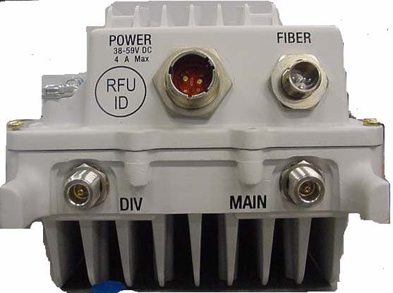
IHET7HN1
Jul 17, 20072.5 GHz Diversity Access Point
Equipment Class
TNB - Licensed Non-Broadcast Station Transmitter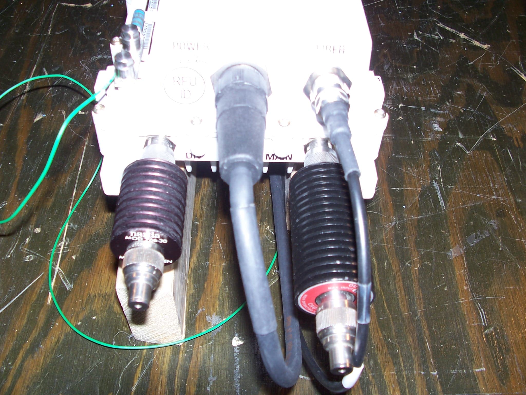
IHET7GT1
Jan 14, 20072.5GHz DIVERSITY ACCESS POINT
Equipment Class
TNB - Licensed Non-Broadcast Station Transmitter