IHET5ZR1SC4812ET 800 MHz CDMA BTS Frame
Nokia Solutions and Networks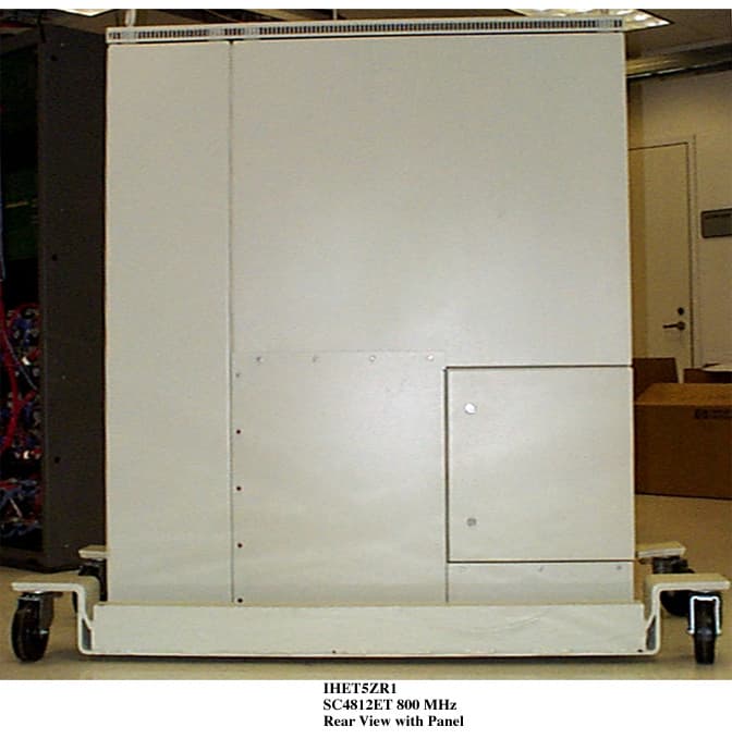
Click to zoom
Application Details
- Equipment Class
- TNB - Licensed Non-Broadcast Station Transmitter
- Date of Grant
- Oct 25, 1999
- Application Purpose
- Original Equipment
- Date of Application
- Aug 18, 1999
- Equipment Note
- SC4812ET 800 MHz CDMA BTS Frame
- Frequency Range
- 869.70000000 - 893.31000000
- Company
- Nokia Solutions and Networks
- Country
- United States
Documents & Files
Document Text
Text extracted from the exhibit documents filed with the FCC. Open a document above to read the original.
Users Manual
Cellular Infrastructure Group FCC ID: IHET5ZR1 USERS MANUAL EXHIBIT PLEASE NOTE: Manual documentation for the SC4812ET @ 800 MHz CDMA BTS is currently under development and is similar to the manual for SC4812ET @ 1.9 Ghz CDMA BTS with FCC ID #IHET6YZ1. Please refer to the attached manual for this submission. TECHNICAL EDUCATION & DOCUMENTATION PREMIER GLOBAL INFORMATION PROVIDER SCt4812ET BTS Optimization/ATP 1900 MHz CDMA 68P64114A42–2 PRELIMINARY 2 CDMA LMF - Software Release 9.0 Notice While reasonable efforts have been made to assure the accuracy of this document, Motorola, Inc. assumes no liability resulting from any inaccuracies or omissions in this document, or from use of the information obtained herein. The information in this document has been carefully checked and is believed to be entirely reliable. However, no responsibility is assumed for inaccuracies or omissions. Motorola, Inc. reserves the right to make changes to any products described herein and reserves the right to revise this document and to make changes from time to time in content hereof with no obligation to notify any person of revisions or changes. Motorola, Inc. does not assume any liability arising out of the application or use of any product, software, or circuit described herein; neither does it convey license under its patent rights or the rights of others. It is possible that this publication may contain references to, or information about Motorola products (machines and programs), programming, or services that are not announced in your country. Such references or information must not be construed to mean that Motorola intends to announce such Motorola products, programming, or services in your country. Copyrights This instruction manual, and the Motorola products described in this instruction manual may be, include or describe copyrighted Motorola material, such as computer programs stored in semiconductor memories or other media. Laws in the United States and other countries preserve for Motorola certain exclusive rights for copyrighted material, including the exclusive right to copy, reproduce in any form, distribute and make derivative works of the copyrighted material. Accordingly, any copyrighted Motorola material contained herein or in the Motorola products described in this instruction manual may not be copied, reproduced, distributed, merged or modified in any manner without the express written permission of Motorola. Furthermore, the purchase of Motorola products shall not be deemed to grant either directly or by implication, estoppel, or otherwise, any license under the copyrights, patents or patent applications of Motorola, as arises by operation of law in the sale of a product. Usage and Disclosure Restrictions License Agreement The software described in this document is the property of Motorola, Inc. It is furnished by express license agreement only and may be used only in accordance with the terms of such an agreement. Copyrighted Materials Software and documentation are copyrighted materials. Making unauthorized copies is prohibited by law. No part of the software or documentation may be reproduced, transmitted, transcribed, stored in a retrieval system, or translated into any language or computer language, in any form or by any means, without prior written permission of Motorola, Inc. High Risk Activities Components, units, or third–party products used in the product described herein are NOT fault–tolerant and are NOT designed, manufactured, or intended for use as on–line control equipment in the following hazardous environments requiring fail–safe controls: the operation of Nuclear Facilities, Aircraft Navigation or Aircraft Communication Systems, Air Traffic Control, Life Support, or Weapons Systems (“High Risk Activities”). Motorola and its supplier(s) specifically disclaim any expressed or implied warranty of fitness for such High Risk Activities. Trademarks and Motorola are registered trademarks of Motorola, Inc. Product and service names profiled herein are trademarks of Motorola, Inc. Other manufacturers’ products or services profiled herein may be referred to by trademarks of their respective companies. Copyright Copyright 1999 Motorola, Inc. All Rights Reserved Printed on Recyclable Paper REV010598 SPECIFICATIONS SUBJECT TO CHANGE WITHOUT NOTICE July 1999 i SC 4812ET BTS Optimization/ATP – CDMA LMF PRELIMINARY 2 Table of Contents SC 4812ET BTS Optimization/ATP – CDMA LMF CDMA 1900 MHz List of Figuresv. . . . . . . . . . . . . . . . . . . . . . . . . . . . . . . . . . . . . . . . . . . . . . . . . . . List of Tablesvii. . . . . . . . . . . . . . . . . . . . . . . . . . . . . . . . . . . . . . . . . . . . . . . . . . . Product Informationxi. . . . . . . . . . . . . . . . . . . . . . . . . . . . . . . . . . . . . . . . . . . . . . Forewordxii. . . . . . . . . . . . . . . . . . . . . . . . . . . . . . . . . . . . . . . . . . . . . . . . . . . . . . . General Safetyxv. . . . . . . . . . . . . . . . . . . . . . . . . . . . . . . . . . . . . . . . . . . . . . . . . . . Revision Historyxvii. . . . . . . . . . . . . . . . . . . . . . . . . . . . . . . . . . . . . . . . . . . . . . . . . Patent Notificationxviii. . . . . . . . . . . . . . . . . . . . . . . . . . . . . . . . . . . . . . . . . . . . . . . Chapter 1: Introduction Optimization Overview1-1. . . . . . . . . . . . . . . . . . . . . . . . . . . . . . . . . . . . . . . . . . . . BTS Equipment Identification1-11. . . . . . . . . . . . . . . . . . . . . . . . . . . . . . . . . . . . . . Chapter 2: Preliminary Operations Preliminary Operations: Overview2-1. . . . . . . . . . . . . . . . . . . . . . . . . . . . . . . . . . . Power Cabinet Initial Power Up2-3. . . . . . . . . . . . . . . . . . . . . . . . . . . . . . . . . . . . . Pre–Power–up Tests2-14. . . . . . . . . . . . . . . . . . . . . . . . . . . . . . . . . . . . . . . . . . . . . . Chapter 3: Optimization/Calibration Optimization/Calibration – Introduction3-1. . . . . . . .…
Text truncated - open the document above for the full version.
Attestation Statements
________________________________________________________________________________________________ FCC Filing - SC4812ET @800 MHz CDMA BTS Frame Network Systems Group CDMA Systems Division FCC ID: IHET5ZR1 STATEMENTS OF CERTIFICATION EXHIBIT ________________________________________________________________________________________________ FCC Filing - SC4812ET @800 MHz CDMA BTS Frame APPLICANT: MOTOROLATRANSCEIVER TYPE: IHET5ZR1 STATEMENT OF CERTIFICATION The technical data supplied with this application, having been taken under our supervision is hereby duly certified. We also certify that this transmit and receive equipment (transceiver type: IHET5ZR1) for cellular system use is in full compliance with all parts of EIA/TIA/IS-97-A “Recommended Minimum Performance Standards for Base Stations supporting Dual Mode Wideband Spread Spectrum Cellular Mobile Stations”, and the applicable portions of FCC Part 22. NAME:Paul Joyce POSITION:Engineering Section Manager BTS Development SIGNEDDATE NAME:Gary Adair POSITION:Lead Engineer Integration, Test and Certification SIGNEDDATE ________________________________________________________________________________________________ FCC Filing - SC4812ET @800 MHz CDMA BTS Frame APPLICANT: MOTOROLATRANSCEIVER TYPE: IHET5ZR1 STATEMENT OF CERTIFICATION I hereby certify that the above application was prepared under my direction and that to the best of my knowledge and belief, the facts set forth in this application and accompanying technical data are true and correct. NAME:Clifford H. Critchett POSITION:Engineering Manager Integration, Test and Certification SIGNEDDATE ________________________________________________________________________________________________ FCC Filing - SC4812ET @800 MHz CDMA BTS Frame APPLICANT: MOTOROLA TRANSCEIVER TYPE: IHET5ZR1 ATTESTATION OF COMPLIANCE TESTING The transceiver type IHET5ZR1 has been tested in accordance with the requirement contained in the appropriate Commission’s regulations. To the best of my knowledge, these tests were performed using measurement procedures consistent with industry or Commission standards and demonstrate that this equipment complies with the appropriate standards. Each unit manufactured, imported or marketed, will conform to the sample tested within the variations that can be expected due to quantity production and testing on a statistical basis. I further certify that the necessary measurements were made at Motorola Inc., located at 5555 N. Beach Street, Fort Worth, Texas, 76137, or at the radiation test facility located at 1605 Liberty School Rd., Azle, TX 76020. NAME:Clifford H. Critchett POSITION:Engineering Manager Integration, Test and Certification SIGNEDDATE
Cover Letter(s)
Network Systems Group CDMA Systems Division August 23, 1999 Federal Communications Commission Authorization & Evaluation Division 7435 Oakland Mills Road Columbia, Maryland 21046 Re: Application for Cellular Transceiver Certification To Whom It May Concern: Motorola Inc., 5555 N. Beach Street, Fort Worth, Texas 76137, herein submits: Check Number: 04-32025 in the amount of $610.00, Application for Equipment Authorization (FCC Form 731/159) and Sections, for Certification of a PCS Cellular Transceiver, FCC ID: IHET5ZR1. Motorola is also the manufacturer of this equipment. Motorola requests that the Schematics Exhibit be kept confidential: The confidential portions have been identified as such on the Uploading Sections Form. The filing fee includes $135.00, the amount for a confidential filing. This equipment has the capability to operate using Code Division Multiple Access (CDMA) on a spread spectrum signal operating in the cellular band. This more efficient modulation scheme can provide 3 to 10 times the number of available voice channels when compared to existing analog technologies. Technical details for this alternate cellular technology (permitted under the cellular service option provisions in section 22 Subpart H of the Commission’s rules) related to certification of this equipment, are provided in the Statements of Certification Exhibit, and throughout the other exhibits. Please contact me by telephone at (817) 245-6122, by Fax at (817) 245-6851, or by correspondence at the address herein if there are further questions or if additional information is needed concerning this filing. Regards, Clifford H. Critchett Engineering Manager Motorola, Inc. Network Solutions Sector 5555 North Beach Street, M/S 7C Fort Worth, Texas 76137
External Photos
FCC Filing - SC4812ET @ 800 MHz CDMA BTS Network Systems Group APPLICANT: MOTOROLA TRANSCEIVER TYPE: IHET5ZR1 SC4812ET @ 800 MHz CDMA BTS EXTERNAL PHOTOS EXHIBIT List of External Photographs Pg. PHOTOGRAPH 2. Front View Doors Closed 3. Front View Doors Open 4. Rear View with Panel 5. Rear View without Panel 6. Left Side View 7. Right Side View 8. Top View
ID Label/Location Info
APPLICANT: MOTOROLAFCC ID: IHET5ZR1 EQUIPMENT NAMEPLATE PER CFR., Title 47, Part 2.925 Model No. ______________ MOTOROLA FCC ID: Serial No. ____________ COMPLIES WITH PART 68, FCC RULES FCC REG. NO. IHEUSA-23899-DT-N REN: 0.3B USOC: RJ11C Graphics to be black A name plate of this type, or one similar to it, will be affixed to every base station. This label is permanent, indelible, and tamper evident. Bar Coding IHET5ZR1
Internal Photos
FCC Filing - SC4812ET @ 800 MHz CDMA BTS Network Systems Group APPLICANT: MOTOROLA TRANSCEIVER TYPE: IHET5ZR1 SC4812ET @ 800 MHz CDMA BTS INTERNAL PHOTOS EXHIBIT Pg. PHOTOGRAPH 2. MPC Front 3. MPC Back 4. GLI2 Front 5. GLI2 Back 6. BBX2 with Cover 7. BBX2 without Cover 8. BBX2 Back 9. MCC x 24E Front 10. MCC x 24E Back 11. CCD Front 12. CCD Back 13. CCD Front with Cover 14. CSM1 Front 15. CSM1 Back 16. CSM2 Front 17. CSM2 Back 18. LPA Front 19. LPA Back 20. LPA without Cover 21. Power Supply Front 22. Power Supply Back 23. CIO Front 24. CIO Back 25. Switch Card Front 26. Switch Card Back 27. AMR Front 28. AMR Back 29. HSO Front 30. HSO Back 31. SPAN I/O Front 32. SPAN I/O Back 33. RGD Front 34. RGD Back 35. LFR Front 36. LFR Back 37. DBPBBX Front with cover 38. DBPBBX Front without cover 39. DBPBBX Back
Operational Description
FCC Filing- SC4812ET @ 800 MHz CDMA BTS1 DESCRIPTIVE INFORMATION FCC FILING FOR SC4812ET @ 800 MHz CDMA BTS The Information in this exhibit is in accordance with the FCC Rules and Regulations, Vol. II, Part 2, Subpart J. Sections 2.983 through 2.999 are addressed. Section 2.983 (a)Name of Applicant and Manufacturer: MOTOROLA Section 2.983 (b) Identification of Equipment: IHET5ZR1 Section 2.983 (c) Quantity Production: Quantity Production is Planned. Section 2.983 (d) Technical Description This Transmitter is intended for use in the Public Cellular Radio Telecommunications Service and is designed in compliance with the FCC Rules and Regulations Title 47, Part 22(H).This transmitter is capable of spread spectrum (CDMA) operation, and allows up to 64 Walsh codes to support Pilot, Sync, Paging and Traffic channels. (1) Types of Emissions This equipment will be capable of operation using wide band spread spectrum techniques employing Direct Sequence Code Division Multiple Access (DS- CDMA) digital communication techniques. For this transmitter, the emission designator is 1M25F9W (per FCC Part 2.201, subpart C). (2)Frequency Range This transmitter operates within the 869.70 to 893.31 MHz Band (per FCC Part 22). This base station will support CDMA operations on channel numbers 1013 through 1023 and 1 through 777 inclusive. (3) Range of Operating Power The rated maximum average power out of the SC4812ET @800 MHz CDMA BTS is 40 W (46.0 dBm). However, in CDMA the actual power output is based on the number of traffic channels in operation. The minimum power occurs when only a pilot signal is present. The maximum power occurs when a pilot along with synchronization, paging, and traffic channels are present. For a FCC Filing- SC4812ET @ 800 MHz CDMA BTS2 typical system setup, the theoretical difference between minimum power and maximum power is 8dB. The output power is variable in 0.25 dB steps. The range is 12 dB. (3) Range of Operating Power (cont.) In addition, the dynamics of a CDMA system allow for what is called “cell breathing”. This allows an operator to vary the range of a cell by controlling the power of the pilot signal. (4) Maximum Power Limits The peak output power of a base station transmitter may not exceed 500 Watts as defined in Part 22.913 (a) (5)Applied voltages and currents into the final transistor elements of the transmitter output: In the CDMA system, the applied voltages and currents into the final transistor elements SRF7042X4 for 40 W output: Drain27.7 VDC Drain Current 2.0 AMPS x 3 Gate Voltage 4 VDC (6) Function of Each Active Device Refer to the Operational Description Exhibit. (7) Complete Circuit Diagrams Refer to the Schematics Exhibit. (8) Instruction/Installation Manual Refer to the Installation Manual Exhibit. (9) Tune-Up/Optimization Procedure Refer to the Users Manual Exhibit. FCC Filing- SC4812ET @ 800 MHz CDMA BTS3 (10) Means for Frequency Stabilization Refer to Section F of the Test Report Exhibit. The Clock Synchronization Module (CSM/CSM2) provides clock and time signals for an SC4812ET @ 800 MHz CDMA BTS. In addition, it provides the primary source, a 3 MHz clock, for the transmit synthesizer in the Broadband Transceiver. The CSM/CSM2 relies on a GPS receiver, either riding piggyback onto the CSM/CSM2 card or remotely located in an integrated package with the GPS antenna as the primary time reference for the ovenized oscillator. Two types of redundancy are provided: 1)Dual CSM/CSM2 cards provide redundancy in case of primary CSM/CSM2 failure. 2) Redundancy is also provided by either a High Stability Oscillator (HSO) or a Low Frequency Reference (LFR), such as a Loran C receiver, residing in a separate slot. The HSO is provided in case of GPS system failure. The CSM/CSM2 uses the received signals as a reference to provide the required clock for the site. The CSM/CSM2 distributes CDMA time, a 19.6608 MHz clock, and a two second synchronization pulse every even second of universal time to the CDMA Clock Distribution (CCD) Cards . The CSM/CSM2 is also responsible for configuration and management of the GPS and LFR systems. CSM/CSM2 software determines on a site basis what the GPS and LFR configurations should be. For future Commercial CDMA systems, GPS and LFR configuration information could optionally be downloaded to the CSM/CSM2 from the GLI2. The CSM/CSM2 is managed by the GLI2. The High Stability Oscillator (HSO) or Low Frequency Time Reference (LFR) is used to provide a stable time reference in case of a GPS system failure or shutdown. The output of the LFR card is routed to the CSM/CSM2 cards, which derive the appropriate time references for the BTS. The current LFR is a LoranC receiver. In areas where LoranC is unavailable, the HSO may be used. FCC Filing- SC4812ET @ 800 MHz CDMA BTS4 (11) Means for Attenuation of Spurious Emissions Refer to Section C of the Test Report Exhibit. Bandpass filters are employed in the transmit RF circuit to attenuate far out spurious emissions. The filter used here is of an air dielectric cavity resonator type. The baseband employs a discrete L-C 7-pole elliptic filter. This filter is used to attenuate sideband noise and close in spurious emissions. In addition, suppression of spurious radiation is obtained by proper shielding techniques. Means for Limiting Modulation Refer to Sections B and E of the Test Report Exhibit. In a CDMA system, the input signal (voice for example) is sampled and coded in a vocoder. This signal is then spread to 1.23 MHz by a pseudo-random spreading code. This spreading code sets the bandwidth of the spread-spectrum signal. If more than one signal is in operation (i.e. more than one voice channel), then the two signals are simply layered one atop the other within the 1.23 MHz band. So, to some extent, the bandwidth of the transmitted signal is limited by the chip rate of the PN spreading code. Primary limiting of the CDMA signal bandwidth is accomplished by the use of a programmable digital limite…
Text truncated - open the document above for the full version.
Parts List/Tune Up Info
FCC Filing- SC4812ET @800 MHz CDMA BTS Frame Summary of Active Devices APPLICANT: MOTOROLA TRANSMITTER TYPE: IHET5ZR1 Multicoupler Preselector Card (MPC6) Device Type Component Description Operating Frequencies MMPT3906LT1Transistor PNP 40V 2AD.C. MMBT3904LT1Transistor NPN 40V 2AD.C. MC33164D-5R2 IC Undervolt Sensing Ckt, MotorolaD.C. MMSZ6685TZener Diode 3.9V 500mV, MotorolaD.C. MMBD6050LT1Diode 70V, 5A, MotorolaD.C. HSMP-3800-L31 RF PIN Diode 824 - 849 MHz PALCE22VIOH-15JC/4 IC Programmable Logic Device D.C. BRPG1204W-TRBicolor LED 70mA 2.5V D.C. BCW69Transistor PNP D.C. CFK-0301RF FET 824 - 849 MHz MGA-82563IC RF Amplifier 824 - 849 MHz SNA-486IC RF Amplifier 824 - 849 MHz MMBZV6ALT1Dual Diode Common Anode 5.6VD.C. MC33060ADR2 PWM Control CircuitD.C. MTD2955ET4 Power MOSFET Pch 60V, 12AD.C. MBRD340T4 Rectifier Schottky, 3A, 40VD.C. FCC Filing- SC4812ET @800 MHz CDMA BTS Frame Multicoupler Preselector Card (MPC6) (continued) Device Type Component Description Operating Frequencies MC33182DR2Low Pwr Dual Op-AmpD.C P6SMB12CAT3 12V Transient Suppressor D.C. MMBD7000 Zener DiodeD.C. RELAY_G6S_2G_DC12 DPDT 12V RelayD.C. MBRS140T3 Schottky Rectifier40V 1AD.C. LT1054IS IC Voltage Converter with Regulator D.C. LM317 Adj. Voltage Regulator 500mA D.C. X9241 IC CMOS Quad EEPOT D.C. MC3303DR2 IC Gen Purpose Quad Op-Amp D.C. X2502D IC EPROM 256x8D.C. FCC Filing- SC4812ET @800 MHz CDMA BTS Frame Group Line Interface II (GLI2) Device Type Component Description Operating Frequencies MB3240T10TBDG60DRAM 4Mx32 DIMM40 MHz VSA5101532.768MHz PLL-VCXO32.768 MHz SG-636PCE40MHz OSC40 MHz MAX732CWEFLASH PWR SUPPLY170 kHz I74F776AFUTURE BUS RX2.048 MHz I74F777AFUTURE BUS TX2.048 MHz LTC1435CSSWITCHER IC230 kHz MPC860MHzP40MICROPROCESSOR40MHz MC10ELT21PECL3 MHz MPC946FAR2CLOCK DIST IC40 MHz, 20 MHz MC68160CFBEEST20 MHz MC34058FTARS485 XCVR4.096 MHz MC74LCX16244DTR2BUFFERS2.048 MHz SX05TR009ZQ01PPC ASIC40MHz MT9082APTSI DIGITAL SWITCH8.192 MHz PEB2254H-V13E1/T1 FRAMER/LIU/HDLC8.192 MHz, 12.352 MHz, 16.384 MHz OR2C26A-3PS208-DBLUCENT FPGA8.192 MHz, 16.384 MHz 20 MHz W42C70-01GZERO DELAY BUFFER16 MHz MAX250ESDRS232 XCVR 9600 - 19.2K BPSMAX251ESD9600 - 19.2K BPS RS232 XCVR FCC Filing- SC4812ET @800 MHz CDMA BTS Frame Broadband Transceiver/Digital Baseband Processor 800MHz BBX2-DBP STLF4014DD Digital Module Device Type Component Description Operating Frequencies XC5210Xilinx FPGA20 MHz, 1 MHz 19.6608 MHz 74LCX574Octal FlipFlop19.6608 MHz BRPG1204W-TRRed/Green LED0 - 2 Hz MMBT3904LT1NPN TransistorDC, 0 - 2 Hz 74ACT02Quad 2In NOR20 MHz AD976212Bit DAC4.9152 MHz AD826AR Dual Op Amp0 - 630 KHz MC79M05BDTRK5V Linear RegulatorDC MC33269DT_3.33.3V Linear RegulatorDC MC33161Univ Voltage RefDC MMSZ5237BT18.2V Zener DiodeDC MC33063ADDC to DC Converter45 KHz MMDF2P02HDR2Dual P-channel FET45 KHz MBRS340T33.0A Schottky Diode45 KHz MC10ELT21DPECL to TTL Converter 3 MHz FCC Filing- SC4812ET @800 MHz CDMA BTS Frame 800MHz BBX2-DBP STLF4014DD (continued) Digital Module cont. Device Type Component Description Operating Frequencies MC10H641Octal ECL to TTL Clk Distibutor19.6608 MHz MC10EL16DECL Buffer19.6608 MHz MC10EL58PECL Buffer19.6608 MHz MC100ELT23PECL to TTL19.6608 MHz 74ABT125DBiCMOS Hex Tri-state BufferDC, 4.096 MHz ISPLSI2032 Lattice CPLD0.5 Hz, 3 MHz, 19.6608, 50 MHz SG615HC-50.0000MHz50 MHz Crystal Oscillator 50 MHz 74HC4066Analog Mux3 MHz 74ACT08Quad 2In AndDC0.5 Hz, 20 MHz 74LCX244Octal Tri-State Buffer 4.096 MHz, MBR0530T10.5A Schottky Diode100Hz FCC Filing- SC4812ET @800 MHz CDMA BTS Frame 800MHz BBX2-DBP STLF4014DD (continued) Digital Module cont. Device Type Component Description Operating Frequencies MC68EN360ZPQUICC20 MHz DS1232SReset/Watchdog2 Hz HSM63620MHz Crystal Oscillator20 MHz 28F800CVFLASH20 MHz MCM518160DRAM20 MHz 74ACT1624416bit Tri-state Buffer20MHz 74ACT2458bit Transceiver20MHz SX02RH029DH01DTC ASIC0.5 Hz 19.6608 MHz 20 MHz IDT74FCT162500ATPV18Bit Transceiver19.6608 MHz MMBD7000LT1Dual Diode DC, 9.6 KHz, 0 - 630 KHz LT1081ISRS-232 Transceiver9.6 KHz MMSZ5243BT1Dual 13V Zener DiodeDC FCC Filing- SC4812ET @800 MHz CDMA BTS Frame 800MHz BBX2-DBP STLF4014DD (continued) RF Control Module Device Type Component Description Operating Frequencies MMBD201LT130V Hot Carrier Diode DC AD680AR2.5VDC ReferenceDC TLC5620Serial Quad DACDC MC14504111in Serial ADC0 - 630 KHz, 1 MHz RXBB Module Device Type Component Description Operating Frequencies AD660011Bit ADC238.4 MHz 19.6608 MHz 39.3216 MHz MSM13R2850DBP ASIC19.6608 MHz 39.3216 MHz MC10ELT20PECL Transceiver19.6608 MHz MC33269DT3.3V Linear RegulatorDC 74ABT125DBiCMOS Hex Tri-state Buffer39.3216 MHz MIC2920A-5.0BS5V Linear RegulatorDC FCC Filing- SC4812ET @800 MHz CDMA BTS Frame 800MHz BBX2-DBP STLF4014DD (continued) RF Reverse Link Module Device Type Component Description Operating Frequencies SMD-KA27RF-to-IF Mixer824-869 MHz 238.4 MHz MMBT3904LT1NPN TransistorDC MRF5812NPN BJT824-869 MHz MMBT3906LT1PNP TransistorDC MRF9411NPN Transistor238.4 MHz AD210Programmable Attenuator238.4 MHz SWD-119MA/COM Switch DC TX Synthesizer Module Device Type Component Description Operating Frequencies MMBT3904LT1NPN TransistorDC MMBT3904LT1NPN Transistor3 MHz MMBT3906LT1NPN TransistorDC MRF9411LT1NPN Transistor869-894 MHz LM29315V Adj. Low Dropout RegulatorDC MLS9109-00881MA/COM Synthesizer module869-894 MHz FCC Filing- SC4812ET @800 MHz CDMA BTS Frame 800MHz BBX2-DBP STLF4014DD (continued) RX Synthesizer Module Device Type Component Description Operating Frequencies MMBT3904LT1NPN Transistor3MHz MMBT3904LT1NPN TransistorDC MRF9411LT1NPN Transistor583-613 MHz LM29315V Adj. Low Dropout RegulatorDC MC79M058-5V RegulatorDC MC332695V Adj. RegulatorDC MMBZ5231BLT15.1V Zener DiodeDC MMBD7000LT1DiodeDC SI9400DYP-channel MOSFETDC MLS9038-00598MA/COM Synthesizer module583-613 MHz MRF0904Amplifier IC583-613 MHz RF Forward Link Module Device Type Component Description Operating Frequencies MMBT3906LT1PNP Transistor DC MMBZ5235BLT16.8V Zener Diode DC MBR0530T10.5A Schottky Diode DC LM2937IMP-5.05 V…
Text truncated - open the document above for the full version.
Test Report
FCC Filing - SC4812ET @800 MHz CDMA BTS Frame APPLICANT: MOTOROLA TRANSCEIVER TYPE: IHET5ZR1 SC4812ET @800 MHz CDMA BTS FRAME TEST REPORT EXHIBIT Index SectionDescription A Summary of RF Measurements B Modulation Characteristics C Spurious & Harmonic Emissions Radiated D Spurious & Harmonic Emissions Conducted E Occupied Bandwidth F Frequency Stability FCC Filing - SC4812ET @800 MHz CDMA BTS Frame Network Systems Group CDMA Systems Division FCC ID: IHET5ZR1 SECTION A SUMMARY OF RF MEASUREMENTS APPLICANT: MOTOROLA TRANSCEIVER TYPE: IHET5ZR1 Summary of Conducted RF Measurements SPUR LEVEL MEASURED (dBm) FREQUENCY (GHz)SPUR LEVEL SPEC (dBm Max) -25.958.03979-13.0 Conducted EngineerDate APPLICANT: MOTOROLA TRANSCEIVER TYPE: IHET5ZR1 Summary of Radiated RF Measurements WORST TRANSMIT RADIATED RF SPUR LEVEL FOR SC4812ET @800 MHz SPUR FREQUENCY (GHz) DISTANCE MEASURED (meters) SPUR LEVEL MEASURED (dBμV/meter) SPUR LEVEL MEASURED (dBm) FCC MAX LIMIT dBm 1.739343.92-51.31-13 FCC Max. Limit Per 47 CFR 22.917: “=Transmitted Power (10 Log10 (Pwatt)) - (43 + 10 Log10 (Pwatt))dBW “=10 Log10 (Pwatt) - (43 + 10 Log10 (Pwatt))dBW “=-43 dBW “=-13 dBm EngineerDate FCC Filing - SC4812ET @800 MHz CDMA BTS Frame Network Systems Group CDMA Systems Division FCC ID: IHET5ZR1 SECTION B MODULATION CHARACTERISTICS FCC Filing - SC4812ET @800 MHz CDMA BTS Frame Network Systems Group CDMA Systems Division SECTION BFCC ID: IHET5ZR1 MODULATION CHARACTERISTICS Maximum Power FCC Filing - SC4812ET @800 MHz CDMA BTS Frame Network Systems Group CDMA Systems Division SECTION BFCC ID: IHET5ZR1 MODULATION CHARACTERISTICS Minimum Power FCC Filing - SC4812ET @800 MHz CDMA BTS Frame Network Systems Group CDMA Systems Division FCC ID: IHET5ZR1 SECTION C SPURIOUS & HARMONIC EMISSIONS RADIATED APPLICANT: MOTOROLA TRANSCEIVER TYPE: IHET5ZR1 Radiated RF Measurements WORST RADIATED RF SPUR LEVEL FOR SC4812ET @800 MHz TRANSMIT CHANNEL SPUR FREQUENCY (GHz) MEASURED SIGNAL LEVEL dBuV/meter MEASURED Signal Level (dBm) FCC, Part 22 MAX LIMIT (dBm) 1013V 1013H 8.697 1.739 38.86 43.92 -56.37 -51.31 -13 -13 777V 777H 8.933 8.933 39.53 39.50 -55.70 -55.73 -13 -13 Converting dBuV/meter to dBm when Part 22 is done at 3 meters. 1. (dBuV/M / 20) *(Inverse Log) = uV/M 2.Log(uV/M /57735) * 20 = dBm Example 43.92 dBuV/m to dBm (43.92 dBuV/m / 20) * (Inverse Log) = 157.09 uV/M Log (157.09 uV/m/ 57735) * 20 = -51.31 dBm If the test is done at 10 meters, the first formula would remain the same. The 2nd is as follows Log[( uV/m * 1/ (3 * 57735)/10)] * 20 dBm Radiated EngineerDate FCC Filing - SC4812ET @800 MHz CDMA BTS Frame Network Systems Group CDMA Systems Division FCC ID: IHET5ZR1 SECTION D SPURIOUS & HARMONIC EMISSIONS CONDUCTED NOTE: The plots for conducted spurious and harmonic emissions are measured in peak mode. The higher (than 46.0 dBm) levels measured in peak mode are expected, due to typical CDMA peak to average performance. The average power level was set to 46.0 dBm using an HP438A power meter. FCC Filing - SC4812ET @800 MHz CDMA BTS Frame Network Systems Group CDMA Systems Division SECTION DFCC ID: IHET5ZR1 SPURIOUS & HARMONIC EMISSIONS CONDUCTED CDMA Transmitter Channel 1013 Maximum Power FCC Filing - SC4812ET @800 MHz CDMA BTS Frame Network Systems Group CDMA Systems Division SECTION DFCC ID: IHET5ZR1 SPURIOUS & HARMONIC EMISSIONS CONDUCTED CDMA Transmitter Channel 1013 Minimum Power FCC Filing - SC4812ET @800 MHz CDMA BTS Frame Network Systems Group CDMA Systems Division SECTION DFCC ID: IHET5ZR1 SPURIOUS & HARMONIC EMISSIONS CONDUCTED CDMA Transmitter Channel 777 Maximum Power FCC Filing - SC4812ET @800 MHz CDMA BTS Frame Network Systems Group CDMA Systems Division SECTION DFCC ID: IHET5ZR1 SPURIOUS & HARMONIC EMISSIONS CONDUCTED CDMA Transmitter Channel 777 Minimum Power FCC Filing - SC4812ET @800 MHz CDMA BTS Frame Network Systems Group CDMA Systems Division FCC ID: IHET5ZR1 SECTION E OCCUPIED BANDWIDTH FCC Filing - SC4812ET @800 MHz CDMA BTS Frame Network Systems Group CDMA Systems Division SECTION EFCC ID: IHET5ZR1 OCCUPIED BANDWIDTH Maximum Power FCC Filing - SC4812ET @800 MHz CDMA BTS Frame Network Systems Group CDMA Systems Division SECTION EFCC ID: IHET5ZR1 OCCUPIED BANDWIDTH Minimum Power FCC Filing - SC4812ET @800 MHz CDMA BTS Frame Network Systems Group CDMA Systems Division FCC ID: IHET5ZR1 SECTION F FREQUENCY STABILITY
Test Setup Photos
MOTOROLA FCC Radiated Testing * *Note: Equipment calibration is in accordance with ISO 9000
Contact Information
Applicant
Steve Mitchell
Technical Contact
Motorola, Inc.Clifford H Critchett
[email protected]817-245-6122
5555 North Beach Street · Fort Worth, Texas · United States
Non-Technical Contact
Motorola, Inc.Melissa A VanDrie
[email protected]817-245-6039
Technical Specifications
| # | Rule Parts | Frequency Range | Power Output | Emission | Tolerance |
|---|---|---|---|---|---|
| 1 | 22.901(d) | 869.7 MHz - 893.31 MHz | 40 W | 1M25F9W | 1.5000000000 ppm |
Other Applications from Nokia Solutions and Networks
IHET4KJ1
Apr 28, 2010LTE 700 MHz Public Safety Base Station Transceiver
Equipment Class
TNB - Licensed Non-Broadcast Station Transmitter
IHET5GX1
Oct 14, 2007UBS CDMA XMI Transceiver at 800 MHz
Equipment Class
TNB - Licensed Non-Broadcast Station Transmitter
IHET6HG1
Sep 12, 2007CDMA Base Station
Equipment Class
PCB - PCS Licensed Transmitter
IHET7HN1
Jul 17, 20072.5 GHz Diversity Access Point
Equipment Class
TNB - Licensed Non-Broadcast Station Transmitter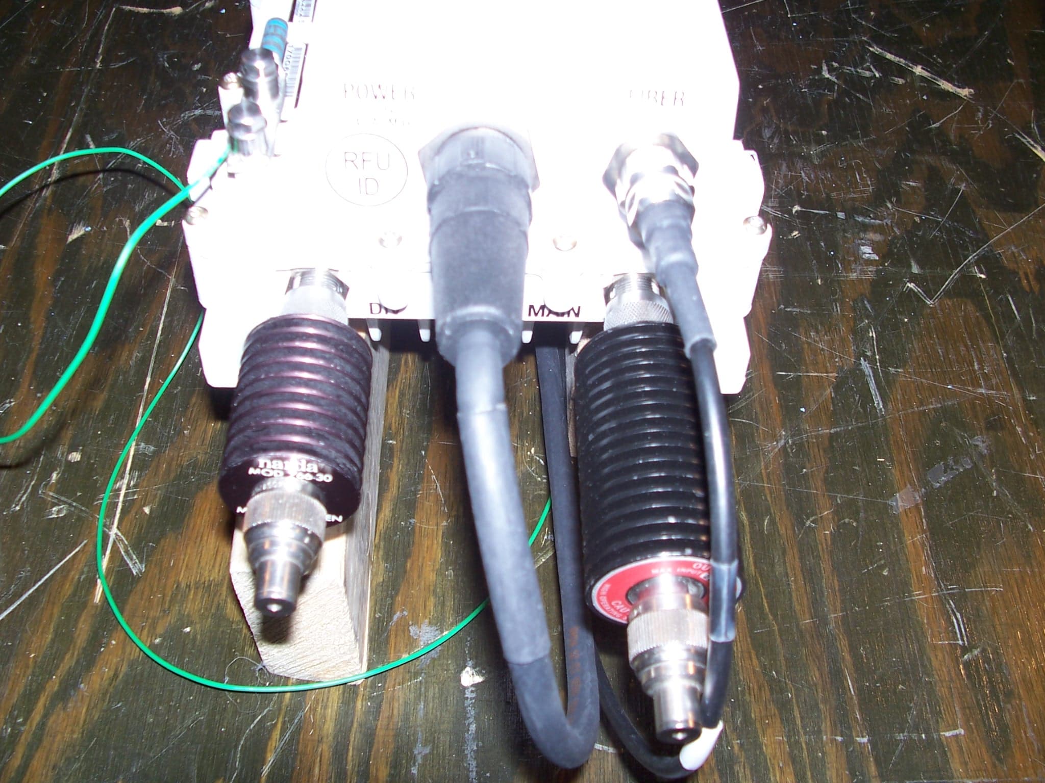
IHET7GT1
Jan 14, 20072.5GHz DIVERSITY ACCESS POINT
Equipment Class
TNB - Licensed Non-Broadcast Station Transmitter