IHET6BM1SC4812ET 1.9 GHz CDMA BTS
Nokia Solutions and Networks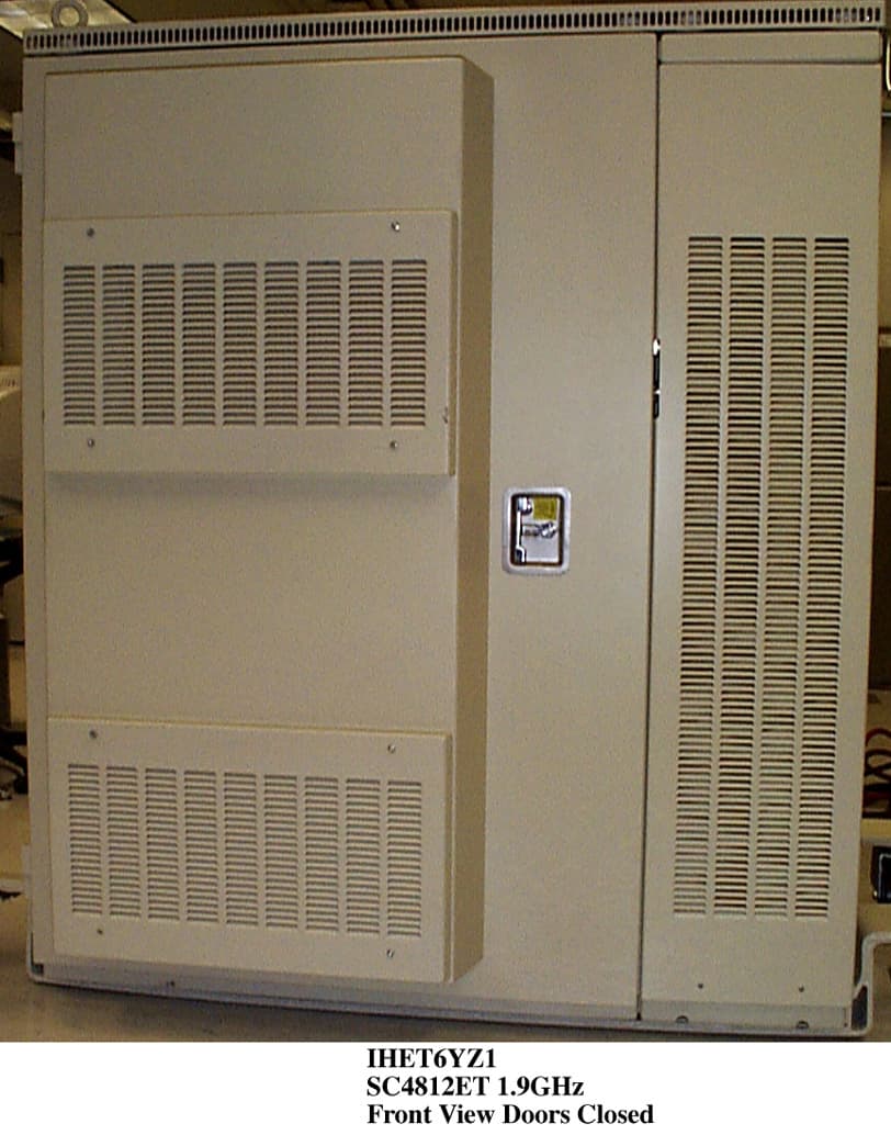
Click to zoom
Application Details
- Equipment Class
- PCB - PCS Licensed Transmitter
- Date of Grant
- Jul 25, 2001
- Application Purpose
- Original Equipment
- Date of Application
- Jul 23, 2001
- Equipment Note
- SC4812ET 1.9 GHz CDMA BTS
- Frequency Range
- 1931.25000000 - 1988.75000000
- Company
- Nokia Solutions and Networks
- Country
- United States
Documents & Files
Document Text
Text extracted from the exhibit documents filed with the FCC. Open a document above to read the original.
Users Manual
SCt4812ET RF and Power Cabinet Hardware Installation Manual System Software Release 2.16.0 800/1700/1900 MHz CDMA English Apr 2001 68P09253A94–1 DRAFT English Apr 2001 68P09253A94–1 SC t 4812ET RF and Power Cabinet Hardware Installation Manual 800/1700/1900 MHz CDMA SCt4812ET RF and Power Cabinet Hardware Installation Manual System Software Release 2.16.0 800/1700/1900 MHz CDMA English Apr 2001 68P09253A94–1 DRAFT Notice While reasonable efforts have been made to assure the accuracy of this document, Motorola, Inc. assumes no liability resulting from any inaccuracies or omissions in this document, or from use of the information obtained herein. The information in this document has been carefully checked and is believed to be entirely reliable. However, no responsibility is assumed for inaccuracies or omissions. Motorola, Inc. reserves the right to make changes to any products described herein and reserves the right to revise this document and to make changes from time to time in content hereof with no obligation to notify any person of revisions or changes. Motorola, Inc. does not assume any liability arising out of the application or use of any product, software, or circuit described herein; neither does it convey license under its patent rights or the rights of others. It is possible that this publication may contain references to, or information about Motorola products (machines and programs), programming, or services that are not announced in your country. Such references or information must not be construed to mean that Motorola intends to announce such Motorola products, programming, or services in your country. Copyrights This instruction manual, and the Motorola products described in this instruction manual may be, include or describe copyrighted Motorola material, such as computer programs stored in semiconductor memories or other media. Laws in the United States and other countries preserve for Motorola certain exclusive rights for copyrighted material, including the exclusive right to copy, reproduce in any form, distribute and make derivative works of the copyrighted material. Accordingly, any copyrighted Motorola material contained herein or in the Motorola products described in this instruction manual may not be copied, reproduced, distributed, merged or modified in any manner without the express written permission of Motorola. Furthermore, the purchase of Motorola products shall not be deemed to grant either directly or by implication, estoppel, or otherwise, any license under the copyrights, patents or patent applications of Motorola, as arises by operation of law in the sale of a product. Usage and Disclosure Restrictions License Agreement The software described in this document is the property of Motorola, Inc. It is furnished by express license agreement only and may be used only in accordance with the terms of such an agreement. Copyrighted Materials Software and documentation are copyrighted materials. Making unauthorized copies is prohibited by law. No part of the software or documentation may be reproduced, transmitted, transcribed, stored in a retrieval system, or translated into any language or computer language, in any form or by any means, without prior written permission of Motorola, Inc. High Risk Activities Components, units, or third–party products used in the product described herein are NOT fault–tolerant and are NOT designed, manufactured, or intended for use as on–line control equipment in the following hazardous environments requiring fail–safe controls: the operation of Nuclear Facilities, Aircraft Navigation or Aircraft Communication Systems, Air Traffic Control, Life Support, or Weapons Systems (“High Risk Activities”). Motorola and its supplier(s) specifically disclaim any expressed or implied warranty of fitness for such High Risk Activities. Trademarks and Motorola are registered trademarks of Motorola, Inc. Product and service names profiled herein are trademarks of Motorola, Inc. Other manufacturers’ products or services profiled herein may be referred to by trademarks of their respective companies. Copyright Copyright 2000 Motorola, Inc. All Rights Reserved Printed on Recyclable Paper REV010598 SPECIFICATIONS SUBJECT TO CHANGE WITHOUT NOTICE Apr 2001 V00.04 5 SC TM 4812ET RF and Power Cabinet Hardware Installation Manual DRAFT Table of Contents SC TM 4812ET RF and Power Cabinet Hardware Installation Manual Release 2.16.0 This manual includes... ChapterVersion DescriptionPage Front V00.04 Foreword, General Safety, Revision History, Patent Notification 3 1 V01.03 Introduction13 2 V02.03 Site Preparation33 3 V03.03 How to Unpack the SC 4812ET BTS59 4 V04.03 Cabinet Mounting67 5 V05.03 Cabinet Cabling81 6 V06.03 What’s Next and Cleanup119 A V0A.03 Installing RGPS123 B VOB.03 Cabinet Specifications127 C VOC.03 Hardware Installation Quickstart137 D VOD.03 SC 4812ET/SC 614 BTS Power Sharing145 E V0F.02 SC 4812ET – SC 614/SC 614T Companion Frame Installation 157 F V0F.02 SC 4812ET to SC 4812ET Power Sharing169 G VOG.01 SC 4812ET – SC 4812ET Companion Frame Installation 185 H VOH.01 Installing RF GPS181 I VOI.01 Minimum Requirements for CSU185 Index189 Foreword DRAFT SC TM 4812ET RF and Power Cabinet Hardware Installation Manual Apr 2001 V00.04 6 Scope of manual This manual is intended for use by cellular telephone system craftspersons in the day-to-day operation of Motorola cellular system equipment and ancillary devices. It is assumed that the user of this information has a general understanding of telephony, as used in the operation of the Public Switched Telephone Network (PSTN), and is familiar with these concepts as they are applied in the cellular mobile/portable radiotelephone environment. The user, however, is not expected to have any detailed technical knowledge of the internal operation of the equipment. This manual is not intended to replace the system and equipment training offered by Motorola, although it can be used to supplement or en…
Text truncated - open the document above for the full version.
Attestation Statements
_________________________________________________________________________________________________________ FCC Filing - SC4812ET @ 1900 MHz CDMA BTS Frame Global Telecom Solutions Sector FCC ID: IHET6BM1 STATEMENTS OF CERTIFICATION EXHIBIT
Cover Letter(s)
Global Telecom Solutions Sector June 12, 2000 Federal Communications Commission Authorization & Evaluation Division 7435 Oakland Mills Road Columbia, Maryland 21046 Re: Application for Cellular Transceiver Certification Gentlemen: Motorola Inc., 1475 W. Shure Drive, Arlington Heights, Illinois 60004, herein submits: Filing fee , Application for Equipment Authorization (FCC Form 731) and Sections, for Certification of a PCS Cel lular Transceiver, FCC ID: IHET6BM1. Motorola is also the manufacturer of this equipment. Motorola requests that the following Sections of the Schematics Exhibit be kept confidential: Section A MPC6 - Multicoupler Preselector Card Section B GLI2 - Group Line Interface Card Section C BBX2- Broadband Transceiver Card Sec tion D MCC x 24E - Multi Channel CDMA Card Section E CCD - CDMA Clock Distribution Card Section F CSM2 - Clock Synchronization Module w/GPS Section G LPA - Linear Power Amplifier Section H CIO - Combiner Input/Output Card Sec tion I Switch Card Sec tion J HSO - High Stability Oscillator Section K SPAN I/O Section L RGD - Remote GPS Distribution Sec tion M LFR- Low Frequency Receiver Special Note The confidential portions have been identified as such on the Uploading Sections Form. The filing fee includes $145.00, the amount for a confidential filing. Page 1 of 2
External Photos
FCC Filing - SC4812ET @1.9 GHz CDMA BTS Global Telecom Solutions Sector APPLICANT: MOTOROLA TRANSCEIVER TYPE: IHET6BM1 SC4812ET @1.9 GHz CDMA BTS EXTERNAL PHOTOS EXHIBIT List of External Photographs NO. PHOTOGRAPH 01Front View Doors Closed 02Front View Doors Open 03Rear View with Panel 04Rear View without Panel 05Left Side View 06Right Side View 07Top View
ID Label/Location Info
APPLICANT: MOTOROLA FCC ID: IHET6BM1 EQUIPMENT NAMEPLATE PER CFR., Title 47, Part 2.925 Bar Coding Graphics to be black A name plate of this type, or one similar to it, will be affixed to every base station. This label is permanent, indelible, and tamper evident. || | |||| | ||| | |||||| | | ||||| ||| ||| || | | ||||||| | Model No.__________________ |||| | | ||| |||| ||||| | | | ||||| | |||| ||| || || || | | Serial No.__________________ MOTOROLA FCC ID: IHET6BM1 Complies with Part 68, FCC Rules FCC Reg. No. IHEUSA-35778-DE-E REN: 03B USOC: RJ11C 1.9 GHz SC4812 ET IHET6BM1 Location of FCC ID Label Side FCC Label (Top of Panel)
Operational Description
FCC Filing- SC4812ET @1.9 GHz CDMA BTS 1 DESCRIPTIVE INFORMATION FCC FILING FOR SC4812ET @1.9 GHz CDMA BTS The Information in this exhibit is in accordance with the FCC Rules and Regulations, Vol. II, Part 2, Subpart J. Sections 2.1033 through 2.1055 are addressed. Section 2.1033 (a) Name of Applicant and Manufacturer: MOTOROLA Section 2. 1033 (b) Identification of Equipment: IHET6BM1 Section 2. 1033 (c) Quantity Production: Quantity Production is planned. Section 2. 1033 (d) Technical Description This Transmitter is intended for use in the Public Cellular Radio Telecommunications Service and is designed in compliance with the FCC Rules and Regulations Title 47, Part 24(E). This transmitter is capable of spread spectrum (CDMA) operation, and allows up to 128 Walsh codes to support Pilot, Sync, Paging, Supplemental, and Traffic channels. (1) Types of Emissions This equipment will be capable of operation using wide band spread spectrum techniques employing Direct Sequence Code Division Multiple Access (DS-CDMA) digital communication techniques. For this transmitter, the emission designator is 1M25F9W (per FCC Part 2.201, subpart C). (2) Frequency Range This transmitter operates within the 1930 to 1990 MHz Band (per FCC Part 24). This base station will support CDMA operations on channel numbers 25 through 1175 (1931.25 MHz - 1988.75 MHz). (3) Range of Operating Power The rated maximum average power out of the SC4812ET @1.9 GHz CDMA BTS is 40 W (46.0 dBm) per RF carrier. However, in CDMA the actual power output is based on the number of traffic channels in operation. The minimum power occurs when only a pilot signal is present. The maximum power occurs when a pilot along with synchronization, paging, and traffic channels are present. For a typical system setup, the theoretical difference between minimum power and maximum power is about 20 dB. The output power is variable in 0.25 dB steps. FCC Filing- SC4812ET @1.9 GHz CDMA BTS 2 (3) Range of Operating Power (cont.) In addition, the dynamics of a CDMA system allow for what is called “cell breathing”. This allows an operator to vary the range of a cell by controlling the power of the pilot signal. (4) Maximum Power Limits The peak output power of a base station transmitter may not exceed 100 Watts as defined in Part 24.232. (5) Applied voltages and currents into the final transistor elements of the transmitter output: In the CDMA system, the applied voltages and currents into the final transistor elements SRF7042X4 for 40 W output: Drain 27.7 VDC Drain Current 1.0 AMPS x 3 Gate Voltage 4 VDC (6) Function of Each Active Device Refer to the Operational Description Exhibit. (7) Complete Circuit Diagrams Refer to the Schematics Exhibit. (8) Instruction/Installation Manual Refer to the Installation Manual Exhibit. (9) Tune-Up/Optimization Procedure Refer to the Users Manual Exhibit. FCC Filing- SC4812ET @1.9 GHz CDMA BTS 3 (10) Means for Frequency Stabilization Refer to Section F of the Test Report Exhibit. The Clock Synchronization Module (CSM/CSM2) provides clock and time signals for an SC4812ET @1.9 GHz CDMA BTS. In addition, it provides the primary source, a 3 MHz clock, for the transmit synthesizer in the Broadband Transceiver. The CSM/CSM2 relies on a GPS receiver, either riding piggyback onto the CSM/CSM2 card or remotely located in an integrated package with the GPS antenna as the primary time reference for the ovenized oscillator. Two types of redundancy are provided: 1) Dual CSM/CSM2 cards provide redundancy in case of primary CSM/CSM2 failure. 2) Redundancy is also provided by either a High Stability Oscillator (HSO) or a Low Frequency Reference (LFR), such as a Loran C receiver, residing in a separate slot. The HSO is provided in case of GPS system failure. The CSM/CSM2 uses the received signals as a reference to provide the required clock for the site. The CSM/CSM2 distributes CDMA time, a 19.6608 MHz clock, and a two second synchronization pulse every even second of universal time to the CDMA Clock Distribution (CCD) Cards . The CSM/CSM2 is also responsible for configuration and management of the GPS and LFR systems. CSM/CSM2 software determines on a site basis what the GPS and LFR configurations should be. For future Commercial CDMA systems, GPS and LFR configuration information could optionally be downloaded to the CSM/CSM2 from the GLI2. The CSM/CSM2 is managed by the GLI2. The High Stability Oscillator (HSO) or Low Frequency Time Reference (LFR) is used to provide a stable time reference in case of a GPS system failure or shutdown. The output of the LFR card is routed to the CSM/CSM2 cards, which derive the appropriate time references for the RF section. The current LFR is a LoranC receiver. In areas where LoranC is unavailable, the HSO may be used. FCC Filing- SC4812ET @1.9 GHz CDMA BTS 4 (11) Means for Attenuation of Spurious Emissions Refer to Section C of the Test Report Exhibit. Band pass filters are employed in the transmit RF circuit to attenuate far out spurious emissions. The filter used here is of an air dielectric cavity resonator type. In addition to the digital filters described below, the baseband also employs a discrete anti-alias filter that attenuates signals greater than 2MHz. Out of band emissions are also attenuated by ceramic filters in the transmit RF lineup. In addition, suppression of spurious radiation is obtained by proper shielding techniques. Means for Limiting Modulation Refer to Sections B and F of the Test Report Exhibit. In a CDMA system, the input signal (voice for example) is sampled and coded in a vocoder. This signal is then spread to 1.23 MHz by a pseudo-random spreading code. This spreading code sets the bandwidth of the spread-spectrum signal. If more than one signal is in operation (i.e. more than one voice channel), then the two signals are simply layered one atop the other within the 1.23 MHz band. So, to some extent, the bandwidth of the transmitted signal is limited by the chip rate of t…
Text truncated - open the document above for the full version.
Test Report
FCC Filing – SC4812ET @ 1.9 GHz CDMA BTS APPLICANT: MOTOROLA TRANSCEIVER TYPE: IHET6BM1 SC4812ET @ 1.9 GHz CDMA BTS TEST REPORT EXHIBIT Index Section Description ASummary of RF Measurements BModulation Characteristics CSpurious and Harmonic Emissions Radiated DSpurious and Harmonic Emissions Conducted EOccupied Bandwidth FFrequency Stability FCC Filing - SC4812ET @ 1.9 GHz CDMA BTS Frame Global Telecom Solutions Sector FCC ID: IHET6BM1 SECTION A Summary of RF Measurements FCC Filing - SC4812ET @ 1.9 GHz CDMA BTS Frame Global Telecom Solutions Sector FCC ID: IHET6BM1 SECTION B Modulation Characteristics Maximum Power FCC Filing - SC4812ET @ 1.9 GHz CDMA BTS Frame Global Telecom Solutions Sector FCC ID: IHET6BM1 Modulation Characteristics Minimum Power
Test Report
FCC Filing - SC4812ET @ 1.9 GHz CDMA BTS Frame Global Telecom Solutions Sector FCC ID: IHET6BM1 Modulation Characteristics Minimum Power
Test Report
FCC Filing - SC4812ET @ 1.9 GHz CDMA BTS Frame Global Telecom Solutions Sector FCC ID: IHET6BM1 SECTION C Spurious & Harmonic Emissions Radiated FCC Filing - SC4812ET @ 1.9 GHz CDMA BTS Frame Global Telecom Solutions Sector FCC ID: IHET6BM1 SECTION D Spurious & Harmonic Emissions Conducted Global Telecom Solutions Sector FCC ID: IHET6BM1 SPURIOUS & HARMONIC EMISSIONS CONDUCTED CDMA Transmitter Channel 25 Maximum Power Global Telecom Solutions Sector FCC ID: IHET6BM1 SPURIOUS & HARMONIC EMISSIONS CONDUCTED CDMA Transmitter Channel 25 Minimum Power Network Systems Group CDMA Systems Division FCC ID: IHET6BM1 SPURIOUS & HARMONIC EMISSIONS CONDUCTED CDMA Transmitter Channel 1175 Maximum Power Global Telecom Solutions Sector FCC ID: IHET6BM1 SPURIOUS & HARMONIC EMISSIONS CONDUCTED CDMA Transmitter Channel 1175 Minimum Power FCC Filing - SC4812ET @ 1.9 GHz CDMA BTS Frame Global Telecom Solutions Sector FCC ID: IHET6BM1 SECTION E Occupied Bandwidth Maximum Power FCC Filing - SC4812ET @ 1.9 GHz CDMA BTS Frame Global Telecom Solutions Sector FCC ID: IHET6BM1 Occupied Bandwidth Minimum Power FCC Filing - SC4812ET @ 1.9 GHz CDMA BTS Frame Global Telecom Solutions Sector FCC ID: IHET6BM1 SECTION F Frequency Stability
Contact Information
Applicant
Steve Mitchell
Technical Contact
Underwriters Laboratories Inc.James R Marley
[email protected](919) 549-1408
12 Laboratory Drive · Research Triangle Park, North Carolina · United States
Non-Technical Contact
Underwriters Laboratories Inc.James R Marley
[email protected](919) 549-1408
Test Firm
UL LLCRick Titus
Technical Specifications
| # | Rule Parts | Frequency Range | Power Output | Emission | Tolerance |
|---|---|---|---|---|---|
| 1 | 24E | 1.93 GHz - 1.99 GHz | 40 W | 1M25F9W | 1.5000000000 ppm |
Other Applications from Nokia Solutions and Networks
IHET4KJ1
Apr 28, 2010LTE 700 MHz Public Safety Base Station Transceiver
Equipment Class
TNB - Licensed Non-Broadcast Station Transmitter
IHET5GX1
Oct 14, 2007UBS CDMA XMI Transceiver at 800 MHz
Equipment Class
TNB - Licensed Non-Broadcast Station Transmitter
IHET6HG1
Sep 12, 2007CDMA Base Station
Equipment Class
PCB - PCS Licensed Transmitter
IHET7HN1
Jul 17, 20072.5 GHz Diversity Access Point
Equipment Class
TNB - Licensed Non-Broadcast Station Transmitter
IHET7GT1
Jan 14, 20072.5GHz DIVERSITY ACCESS POINT
Equipment Class
TNB - Licensed Non-Broadcast Station Transmitter