IHET6EK11X-EVDO SC480 BTS Microcell Base Station Transmtr
Nokia Solutions and Networks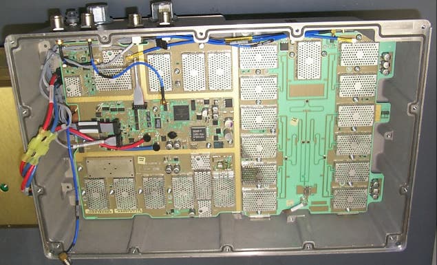
Click to zoom
Application Details
- Equipment Class
- PCB - PCS Licensed Transmitter
- Date of Grant
- Jul 07, 2004
- Application Purpose
- Original Equipment
- Date of Application
- Jul 07, 2004
- Equipment Note
- 1X-EVDO SC480 BTS Microcell Base Station Transmtr
- Frequency Range
- 1931.25000000 - 1988.75000000
- Company
- Nokia Solutions and Networks
- Country
- United States
Documents & Files
Document Text
Text extracted from the exhibit documents filed with the FCC. Open a document above to read the original.
Users Manual
DRAFT 68P09262A08–1 JUN 2004 ENGLISH CDMA2000 1X SOFTWARE RELEASE 2.16.5.X Technical Information 1X SC480 BTS HARDWARE INSTALLATION, OPTIMIZATION/ATP, AND FRU 1.9 GHZ DRAFT SPECIFICATIONS SUBJECT TO CHANGE WITHOUT NOTICE Notice While reasonable efforts have been made to assure the accuracy of this document, Motorola, Inc. assumes no liability resulting from any inaccuracies or omissions in this document, or from use of the information obtained herein. The information in this document has been carefully checked and is believed to be entirely reliable. However, no responsibility is assumed for inaccuracies or omissions. Motorola, Inc. reserves the right to make changes to any products described herein and reserves the right to revise this document and to make changes from time to time in content hereof with no obligation to notify any person of revisions or changes. Motorola, Inc. does not assume any liability arising out of the application or use of any product, software, or circuit described herein; neither does it convey license under its patent rights or the rights of others. It is possible that this publication may contain references to, or information about Motorola products (machines and programs), programming, or services that are not announced in your country. Such references or information must not be construed to mean that Motorola intends to announce such Motorola products, programming, or services in your country. Copyrights This instruction manual, and the Motorola products described in this instruction manual may be, include or describe copyrighted Motorola material, such as computer programs stored in semiconductor memories or other media. Laws in the United States and other countries preserve for Motorola and its licensors certain exclusive rights for copyrighted material, including the exclusive right to copy, reproduce in any form, distribute and make derivative works of the copyrighted material. Accordingly, any copyrighted material of Motorola and its licensors contained herein or in the Motorola products described in this instruction manual may not be copied, reproduced, distributed, merged or modified in any manner without the express written permission of Motorola. Furthermore, the purchase of Motorola products shall not be deemed to grant either directly or by implication, estoppel, or otherwise, any license under the copyrights, patents or patent applications of Motorola, as arises by operation of law in the sale of a product. Usage and Disclosure Restrictions License Agreement The software described in this document is the property of Motorola, Inc and its licensors. It is furnished by express license agreement only and may be used only in accordance with the terms of such an agreement. Copyrighted Materials Software and documentation are copyrighted materials. Making unauthorized copies is prohibited by law. No part of the software or documentation may be reproduced, transmitted, transcribed, stored in a retrieval system, or translated into any language or computer language, in any form or by any means, without prior written permission of Motorola, Inc. High Risk Activities Components, units, or third–party products used in the product described herein are NOT fault–tolerant and are NOT designed, manufactured, or intended for use as on–line control equipment in the following hazardous environments requiring fail–safe controls: the operation of Nuclear Facilities, Aircraft Navigation or Aircraft Communication Systems, Air Traffic Control, Life Support, or Weapons Systems (“High Risk Activities”). Motorola and its supplier(s) specifically disclaim any expressed or implied warranty of fitness for such High Risk Activities. Trademarks MOTOROLA and the Stylized M Logo are registered in the US Patent & Trademark Office. All other product or service names are the property of their respective owners. © Copyright 2003, 2004 Motorola, Inc. Javat Technology and/or J2MEt: Java and all other Java–based marks are trademarks or registered trademarks of Sun Microsystems, Inc. in the U.S. and other countries. UNIX R : UNIX is a registered trademark of The Open Group in the United States and other countries. REV091302 Jun 20041X SC480 BTS Hardware Installation, Optimization/ATP, and FRU i DRAFT Table of Contents 1X SC480 BTS Hardware Installation, Optimization/ATP, and FRU Software Release 2.16.5.X List of Figuresvi . . . . . . . . . . . . . . . . . . . . . . . . . . . . . . . . . . . . . . . . . . . . . . . . . . . List of Tablesxii . . . . . . . . . . . . . . . . . . . . . . . . . . . . . . . . . . . . . . . . . . . . . . . . . . . Forewordxxi . . . . . . . . . . . . . . . . . . . . . . . . . . . . . . . . . . . . . . . . . . . . . . . . . . . . . . . FCC Requirementsxxiii . . . . . . . . . . . . . . . . . . . . . . . . . . . . . . . . . . . . . . . . . . . . . . . General Safetyxxvi . . . . . . . . . . . . . . . . . . . . . . . . . . . . . . . . . . . . . . . . . . . . . . . . . . . Revision Historyxxviii . . . . . . . . . . . . . . . . . . . . . . . . . . . . . . . . . . . . . . . . . . . . . . . . . Chapter 1: Introduction Introduction1-1 . . . . . . . . . . . . . . . . . . . . . . . . . . . . . . . . . . . . . . . . . . . . . . . . . . . . . Required Documents1-5 . . . . . . . . . . . . . . . . . . . . . . . . . . . . . . . . . . . . . . . . . . . . . . CDMA 1.9 GHz Operating Frequency Programming Information1-8 . . . . . . . . . . Installation Tools and Materials1-11 . . . . . . . . . . . . . . . . . . . . . . . . . . . . . . . . . . . . . ATP Tools and Materials1-14 . . . . . . . . . . . . . . . . . . . . . . . . . . . . . . . . . . . . . . . . . . BTS Equipment Identification1-20 . . . . . . . . . . . . . . . . . . . . . . . . . . . . . . . . . . . . . . Outdoor Enclosure Equipment Identification1-29 . . . . . . . . . . . . . . . . . . . . . . . . . . . Installation and ATP Order1-32 . . . . . . . . . . . . . . . . . . . . . . . . . . . . . . . . . . . . . . . . . Chapte…
Text truncated - open the document above for the full version.
Users Manual
Span Line, RGPS, and RF–GPS Cabling – continued Jun 2004 4-67 1X SC480 BTS Hardware Installation, Optimization/ATP, and FRU DRAFT Connecting Customer–Defined Inputs to the CBIO The unit provides eight customer–defined inputs for connection to external contacts. Each input (a signal/ground pair) is monitored for an “OPEN” (>50 k Ohms) or “CLOSED” (<3 Ohms) condition. RGPS or RF–GPS Installation If RGPS is being installed, proceed to Table 4-36. If RF–GPS is being installed, proceed to Table 3-7. Cable Pinout Figure 4-42 shows the connector pins on cables C and C1. Table 4-35 gives the pinout for cable C and C1. Figure 4-42: Connector Pins Numbering for Cables C and C1 1 2 3 4 5 6 7 8 9 10 1112 CONNECTOR FOR CABLE C PIN 1 CONNECTOR FOR CABLE C1 PIN 9 Table 4-35: Pinout for Cables C and C1 Cable CWire ColorCable C1 PinSignalPin 9DC Ground 1Blue–Black15 1Power 1Blue8 8DC Ground 2Yellow–Black14 10Power 2Yellow7 4Transmit Port (–)Green–Black9 5Transmit Port (+)Green1 2Receive Port (–)White–Black12 3Receive Port (+)White4 7No ConnectRed–BlackNo Connect table continued on next page 4 Span Line, RGPS, and RF–GPS Cabling – continued DRAFT 1X SC480 BTS Hardware Installation, Optimization/ATP, and FRU Jun 2004 4-68 Table 4-35: Pinout for Cables C and C1 Cable CCable C1Wire Color PinPinSignal 6No ConnectRedNo Connect 12PPS Timing (–)Brown–Black10 11PPS Timing (+)Brown2 Wire colors are the same for both cables. Procedure to Install the RGPS Head The RGPS is connected to the BTS via the RGPS connector on the CBIO Board. See Figure 4-41. Site specific characteristics determine the GPS cabling that is installed. Install each cable by referring to the cabling diagram in Figure 4-41, and the procedure in Table 4-36. The lightning arrestor connections are shown in Figure 4-46. Figure 4-43 and Figure 4-44 show the RGPS head. Be sure to factor in mounting considerations as described in Chapter 3. The RGPS head must not make contact with any metal surface other than the provided hardware. Use only the equipment provided to mount the RGPS head. Failure to do so could damage the RGPS head. CAUTION Table 4-36: Procedure for Installing the RGPS Head and Cabling StepAction 1Determine the mounting location. 2 n WARNING The structure of the wall should be verified by a qualified structural engineer. Mounting the RGPS head and hardware to an inadequate wall structure and/or using inadequate installment methods can result in serious personal injury. Use the appropriate mounting bolts for the mounting surface and install the two wall mounting brackets. Refer to Figure 4-43. 3Remove RF–GPS cover plate from CBIO Board. Remove protective connector cover. 4Connect cables C and C1 into the punch block, as if they were part of the same cable, cut in the middle maintaining color code and signal integrity. Connect the same corresponding color on both sides of the punchblock (see Figure 4-41 and Table 4-35). 4 Span Line, RGPS, and RF–GPS Cabling – continued Jun 2004 4-69 1X SC480 BTS Hardware Installation, Optimization/ATP, and FRU DRAFT Table 4-36: Procedure for Installing the RGPS Head and Cabling StepAction 5Connect RGPS cable (cable C1) to D–connector. Attach ferrite bead on the cable close to the BTS connector. 6Route RGPS cable C (12–pin Deutsch connector) into the pipe. 7Mate the 12–pin Deutsch connector of the RGPS Head cable and cable C. Refer to Figure 4-43. Tighten the spinning flange on the connector a quarter turn to secure the connection. 8Insert the pipe into the threaded mount in the RGPS Head and carefully hand–tighten. 9Place the assembly into the mounting brackets. Refer to Figure 4-43. Tighten the U–bolt clamps to secure the assembly. Figure 4-43: Installing the Remote GPS Head WALL MOUNTING BRACKETS (2) CLAMP BRACKETS (2) U–BOLTS CABLE TO PUNCHBLOCK (CABLE C) REFER TO VIEW A RGPS HEAD WITH 12 PIN MALE CONNECTOR MATING CONNECTORS RGPS INTERFACE CABLE WITH 12 PIN FEMALE CONNECTOR ON ONE END AND UNTERMINATED WIRE ON OTHER END VIEW A RGPS HEAD (MOTOROLA PART NUMBER 0186012H03) 1 NOTE: 1. REPLACEMENT RGPS HEAD (MOTOROLA PART NUMBER 0186012H04) CABLE TO PUNCHBLOCK (CABLE C) 4 Span Line, RGPS, and RF–GPS Cabling – continued DRAFT 1X SC480 BTS Hardware Installation, Optimization/ATP, and FRU Jun 2004 4-70 Figure 4-44: RGPS Head THREADED MOUNT ADAPTER 12–PIN DEUTSCH TYPE MMP CONNECTOR Connecting the RGPS Cable to Lightning Arrestor Figure 4-45 is a detail of the RGPS connections. Figure 4-46 is a detail of the Lightning Arrestor connections. Figure 4-45: RGPS to SC480 Connection Diagram Blue/Black Blue Yellow/Black Yellow Green/Black Green White/Black White Red/Black Red Brown/Black Brown 1 2 3 4 5 6 7 8 9 10 11 12 Earth Ground RGPS CABLE CONNECTOR (VIEWED FROM CABLE PERSPECTIVE) C CABLE DRAIN LIGHTNING ARRESTOR (WNP CGDSO971017AA1 OR EQUIVALENT) D–CONNECTOR TO BTS CELL SITE GROUND = C1 UNUSED 1 14 10 2 4 12 7 8 15 9 RGPS HEAD (MOTOROLA P/N 0186012H04) 4 Span Line, RGPS, and RF–GPS Cabling – continued Jun 2004 4-71 1X SC480 BTS Hardware Installation, Optimization/ATP, and FRU DRAFT Blue/Black Blue Yellow/Black Yellow Green/Black Green White/Black White Red/Black Red Brown/Black Brown Cable Drain Blue/Black Blue Yellow/Black Yellow Green/Black Green White/Black White Red/Black Red Brown/Black Brown Cable Drain +40V DC Lines +17V DC Lines +17V DC Lines +17V DC Equipment +17V DC Equipment +40V DC Equipment C1 (RGPS) TO BTS UNIT C (RGPS) TO RGPS RECEIVER EARTH GROUND MOUNTING PLATE Blue/Black Blue Yellow/Black Yellow Green/Black Green White/Black White Red/Black Red Brown/Black Brown 1 2 3 4 5 6 7 8 9 10 11 12 Figure 4-46: RGPS Lightning Arrestor Wiring Connecting the RF–GPS Cable Figure 4-47 shows the components of the RF–GPS. The RF–GPS is connected to the BTS via the RF–GPS module through the RGPS connector on the CBIO Board. See Figure 4-48. Procedure Use the procedure in Table 4-37 to install the RF–GPS system. Table 4-37: Procedure for Installing RF–GPS Antenna and Cabling StepAction 1Determine the mounting locatio…
Text truncated - open the document above for the full version.
Users Manual
Packet BTS Shut Down Procedures – continued Jun 20041X SC480 BTS Hardware Installation, Optimization/ATP, and FRU 10-43 DRAFT Table 10-9: Shut Down Sector Signaling Functions Procedure For a Packet BTS nActionStep NOTE This step edits the REDIRECT2 parameters so that the Global Service Redirect Message to be broadcast on the paging channel redirects all subscribers away from the sector with the failed equipment and onto a CDMA channel at a neighbor sector/site. 8Enter the following command at the prompt: omc–000000>EDIT SECTOR–<bts#>–<sector#> REDIRECT2 ! The system prompts you to enter each command parameter value one at a time. Answer the prompts in the following order: expecting an integer number (from 0 to 65535) <EXPNID= ? > (Use the Network ID the subscriber units should expect to find on the system they are being redirected to. This example uses 555.) expecting an integer number (from 0 to 2047) <CHAN1= ? >, <CHAN2= ? > ... <CHAN15= ?> (A list of CDMA channels for neighbor sites that the subscriber units can use for redirection. This example uses 200, 350, 400, 725, 75, 175, 100, 575 and 950.) expecting an enumerated value: CDMA1900 CDMA800 CDMA900 JAPANCDMA <BANDCLASS= ? > (Use CDMA1900 for 1.9 GHz systems, and CDMA800 for 800 MHz systems. This example uses CDMA1900.) The system displays the command to be sent. Verify the command syntax. omc–000000>Accept [yes/no]? Enter Y to accept the command or N to go back and enter the correct value(s). 9View the status of the sector signaling REDIRECT2 parameters to verify that the sector is ready for maintenance. omc–000000>DISPLAY SECTOR–<bts#>–<sector#> REDIRECT2 Ensure that the values in the system display response match the values input in Step 8 (see example below). REDIRECT CHAN CARRIER ID EXP BAND (bts–sector–carrier) NID CLASS 1 2 3 4 5 6 7 8 9 10 11 12 13 14 15 –––––––––––––––––––– ––––– ––––––––– ––– ––– ––– ––– ––– ––– –––– –––– –––– –––– –––– –––– –––– ––– –––– CARRIER–146–2–1 555 CDMA1900 200 350 400 725 75 175 100 575 950 – – – – – – . . . continued on next page 10 Packet BTS Shut Down Procedures – continued 10-441X SC480 BTS Hardware Installation, Optimization/ATP, and FRUJun 2004 DRAFT Table 10-9: Shut Down Sector Signaling Functions Procedure For a Packet BTS nActionStep 10View the existing congestion control parameters for all carriers equipped for the applicable sector by entering the following command at the prompt: omc–000000>DISPLAY SECTOR–<bts#>–<sector#> CONGESTCONF Observe the following typical system display response for sector 1: CARRIER NEWCALL REG AGG (bts#–sector#–carrier#) SET ALARMFLAG ALARMFLAG ALARMFLAG ANALOGREDIRECT GLOBALREDIRECT ––––––––––––––––––––––– ––– ––––––––– –––––––––– –––––––––– –––––––––––––– –––––––––––––– 146–2–1 1 ENABLE ENABLE ENABLE DISABLE DISABLE NOTE In this step, you will change the value of the Global Service Redirection Flag (GLOBALREDIRECT) in the congestion control parameters so that the Global Service Redirect Message is broadcast on the sector paging channel. 11Enter the following command at the prompt: omc–000000>EDIT SECTOR–<bts#>–<sector#> CONGESTCONF ! The system prompts you to enter each control parameter value one at a time. Skip through the prompts until you get to the following: <globalredirect> , enter ENABLE (This forces the Global Service Redirect Message to be broadcast on the sector paging channel.) The system displays the values of the control parameters. Verify that only the GLOBALREDIRECT value changed. omc–000000>Accept [yes/no]? Enter Y to accept the change. Now the Global Service Redirection Message is sent over the sector paging channels. All subscribers are redirected away from the sector and onto a different system. This effectively shuts down the sector. 12Verify that the CONGESTCONF globalredirect is enabled for each carrier on the sector by entering the following command at the prompt: omc–000000>DISPLAY SECTOR–<bts#>–<sector#> CONGESTCONF Observe the following typical system display response for sector 1: CARRIER NEWCALL REG AGG (bts#–sector#–carrier#) SET ALARMFLAG ALARMFLAG ALARMFLAG ANALOGREDIRECT GLOBALREDIRECT ––––––––––––––––––––––– ––– ––––––––– –––––––––– –––––––––– –––––––––––––– –––––––––––––– 146–2–1 1 ENABLE ENABLE ENABLE DISABLE ENABLE 13Display the status of all devices at the BTS by entering the following command at the prompt: omc–000000>DISPLAY BTS–<bts#> STATUS Record the system response for all devices that are OOS_AUTOMATIC. . . . continued on next page 10 Packet BTS Shut Down Procedures – continued Jun 20041X SC480 BTS Hardware Installation, Optimization/ATP, and FRU 10-45 DRAFT Table 10-9: Shut Down Sector Signaling Functions Procedure For a Packet BTS nActionStep NOTE SHUTDOWN and REDIRECT both prevent future calls from being originated on the targeted resource, but only SHUTDOWN waits indefinitely for the calls to terminate. When the resource becomes idle, SHUTDOWN automatically transitions the resource to the locked/disabled state. 14If you redirected subscribers but do not want to use SHUTDOWN, go to step 15. If you redirected subscribers and want to use SHUTDOWN, go to step 16. 15Wait three minutes to allow any active calls to terminate then go to step 18. 16Shutdown all carriers equipped for the target sector at the BTS by repeatedly entering the following command at the prompt: omc–000000>SHUTDOWN CARRIER–<bts#>–<sector#>–<carrier#> Repeat this command for each sector–carrier associated with the target sector. NOTE When a BBX is keyed, it is in an UNLOCKED/ENABLED/ACTIVE state. When a BBX is in an UNLOCKED/ENABLED/IDLE state, it is dekeyed and INS_STANDBY. As long as the sector–carrier associated with the BBX is LOCKED/DISABLED/IDLE, the BBX cannot be keyed. Also the redundant BBX does not switchover for an INS_STANDBY primary BBX. 17Observe that the system automatically returns a “Network Element State Change Event” message for each carrier after it is shutdown. This message shows the old and new states for the carrier. Th…
Text truncated - open the document above for the full version.
Users Manual
Compact BTS Expansion Configuration (Indoor) – continued E-181X SC480 BTS Hardware Installation, Optimization/ATP, and FRUJun 2004 DRAFT Figure E-8: Two Expansion BTSes Cabling Diagram EXPANSION 2 EXPANSION 1 STARTER LOCAL GPS Power and Ground not shown Ensure that the expansion BTSes have the expansion cMPC cards installed. COMBINER TX 1 RX MAIN RX DIV TX 2 DC LA LA LA E Compact BTS Expansion Configuration (Indoor) – continued Jun 20041X SC480 BTS Hardware Installation, Optimization/ATP, and FRU E-19 DRAFT EXPANSION 1 STARTER LOCAL GPS Figure E-9: One Expansion BTS Cabling Diagram Power and Ground not shown Ensure that the expansion BTS has an expansion cMPC card installed. TX 1 RX MAIN RX DIV LA LA LA E Compact BTS Expansion Configuration (Indoor) – continued E-201X SC480 BTS Hardware Installation, Optimization/ATP, and FRUJun 2004 DRAFT Table E-11: BBX (Carrier) to cCLPA Via RS485 BTScCLPA Starter – BBX1cCLPA–1 Starter – BBX4cCLPA–1 Expansion 1 – BBX1cCLPA–2 Expansion 1 – BBX4cCLPA–2 Expansion 2 – BBX1cCLPA–1 Expansion 2 – BBX4cCLPA–1 Expansion 3 – BBX1cCLPA–2 Expansion 3 – BBX4cCLPA–2 Table E-12 shows in tabular format the BTS–to–cCLPA cabling of Figure E-1. Table E-12: Starter and Three Expansion BTS Cabling for Circuit or Packet to Dual cCLPAs BTScCLPA Starter – BBX1CPA–A (CPA–1) Starter – BBX4CPA–A (CPA–1) Expansion 1 – BBX1CPA–B (CPB–2) Expansion 1 – BBX4CPA–B (CPB–2) Expansion 2 – BBX1CPA–A (CPA–1) Expansion 2 – BBX4CPA–A (CPA–1) Expansion 3 – BBX1CPA–B (CPA–2) Expansion 3 – BBX4CPA–B (CPA–2) Starter and Two Expansion BTSes to cCLPA Cabling Table E-13 shows in tabular format the BTS–to–cCLPA cabling of Figure E-2. E Compact BTS Expansion Configuration (Indoor) – continued Jun 20041X SC480 BTS Hardware Installation, Optimization/ATP, and FRU E-21 DRAFT Table E-13: Starter and Two Expansion BTS Cabling for Circuit or Packet to Dual cCLPAs BTScCLPA Starter – BBX1CPA–A (CPA–1) Starter – BBX4CPA–A (CPA–1) Expansion 1 – BBX1CPA–B (CPB–2) Expansion 1 – BBX4CPA–B (CPB–2) Expansion 2 – BBX1CPA–A (CPA–1) Expansion 2 – BBX4CPA–A (CPA–1) Starter and One Expansion BTS to cCLPA Cabling Table E-14 shows in tabular format the BTS–to–cCLPA cabling of Figure E-3. Table E-14: Starter and One Expansion BTS Cabling for Circuit or Packet to Dual cCLPAs BTScCLPA Starter – BBX1CPA–A (CPA–1) Starter – BBX4CPA–A (CPA–1) Expansion 1 – BBX1CPA–B (CPB–2) Expansion 1 – BBX4CPA–B (CPB–2) E Multiple Compact BTS Configuration (Outdoor) E-221X SC480 BTS Hardware Installation, Optimization/ATP, and FRUJun 2004 DRAFT Introduction This section covers only the outdoor version of the multiple Compact BTS configuration. Materials Needed The following materials are required to configure expansion BTSes. SVaried length cables with RJ45 connectors SVaried length cables with RF connectors SConduit (customer supplied) SDC Power source (custoemr supplied) SBattery Backup (customer supplied) External Combiner and Directional Coupler A combiner and directional coupler are required for some of the configurations. The following are the recommended specifications for the combiner and directional coupler. Table E-15: Combiner and Directional Coupler Specifications ItemSpecifications Combiner Connector:N–Type Frequency Range:Up to 2 GHz Insertion Loss:3.5 dB maximum Return Loss:16 dB minimum Average Input Power:60 Watts minimum Directional Coupler Connector:N–Type Frequency Range:810 to 950 MHz Coupling:30 +/–1 dB Directivity:28 dB minimum Return Loss:18 dB minimum Average Input Power:10 Watts minimum SMotorola recommended directional coupler is P/N 809643T03 SRecommended cable with combiner is Andrew LDF4–50 or equivalent E Multiple Compact BTS Configuration (Outdoor) – continued Jun 20041X SC480 BTS Hardware Installation, Optimization/ATP, and FRU E-23 DRAFT SDirectional coupler and combiner are not environmentally protected , and so must be placed within the TME. ExpansionCompact BTS Installation Procedure Follow the procedure in Table E-16for installation of multiple Compact BTSes. Table E-16: Procedure for Installing Expansion Compact BTSes StepAction 1Follow the procedure in Chapter 4 for installing a Compact BTS in a rack. 2For a 3 BTS expansion configuration, follow Figure E-1. Proceed to step 3. 2aFor a 2 BTS expansion configuration, follow Figure E-2. Proceed to step 3. 2bFor a 1 BTS expansion configuration, follow Figure E-3. Proceed to step 3. 3If conduit is not used, dress cables as necessary. 4Perform Optimization and ATP as described in Chapter 6. LMF Help provides further information. Frame ID Switch Settings Refer to Chapter 5, Figure 5-1 or Figure 5-2 or Table 5-1 through Table 5-4 for the Frame DIP Switch settings. E Multiple Compact BTS Configuration (Outdoor) – continued E-241X SC480 BTS Hardware Installation, Optimization/ATP, and FRUJun 2004 DRAFT Figure E-10: Three Expansion BTSes Cabling Diagram LIGHTNING ARRESTOR LIGHTNING ARRESTOR EXPANSION 3 EXPANSION 2 EXPANSION 1 STARTER cCLPA 1 cCLPA 2 LOCAL GPS TX1 TX2 RX DIV RX MAIN TME ANTENNA CONNECTORS TME RF–GPS CONNECTOR Power and Ground not shown E Multiple Compact BTS Configuration (Outdoor) – continued Jun 20041X SC480 BTS Hardware Installation, Optimization/ATP, and FRU E-25 DRAFT Figure E-11: Outdoor Two Expansion BTSes Cabling Diagram LIGHTNING ARRESTOR LIGHTNING ARRESTOR EXPANSION 2 EXPANSION 1 STARTER cCLPA 1 cCLPA 2 LOCAL GPS TME RF–GPS CONNECTOR TX2 TX1 RX MAIN RX DIV TME ANTENNA CONNECTORS Power and Ground not shown E Multiple Compact BTS Configuration (Outdoor) – continued E-261X SC480 BTS Hardware Installation, Optimization/ATP, and FRUJun 2004 DRAFT LIGHTNING ARRESTOR LIGHTNING ARRESTOR EXPANSION 1 STARTER cCLPA 1 cCLPA 2 LOCAL GPS Figure E-12: Outdoor One Expansion BTS Cabling Diagram TME RF–GPS CONNECTOR TX1 RX MAIN RX DIV TX2 TME ANTENNA CONNECTORS Power and Ground not shown Other Diagrams For single cCLPA and no cCLPA, refer to the diagrams for indoor and allow for the TME connectors as shown in the diagrams presented in this appendix. E Jun …
Text truncated - open the document above for the full version.
Cover Letter(s)
M APPLICANT: MOTOROLA Global Telecom Solutions Sector FCC ID: IHET6EK1 FCC Filing – SC480 1X-EVDO with cPAs @ 1.9 GHz CDMA BTS 1 of 2 July 2, 2004 Federal Communications Commission Authorization & Evaluation Division 7435 Oakland Mills Road Columbia, Maryland 21046 Re: Application for Cellular Transceiver Certification Gentlemen: Motorola Inc., 1475 W. Shure Drive, Arlington Heights, Illinois 60004, herein submits: Filing fee , Application for Equipment Authorization (FCC Form 731) and Sections, for Certification of a Cel lular Transceiver, FCC ID: IHET5EJ1. Motorola is also the manufacturer of this equipment. Motorola requests that the following Sections of the Schematics Exhibit be kept confidential: Section A CMPC - Compact Multicoupler Preselector Card Section B GLI3 - Group Line Int erface Card Section C BBX-1X – Broadband Transceiver Card Section D MCC-1X – Multi Channel CDMA Card Section E MCC-DO – Multi Channel CDMA Card Section F CSA - Clock Synchronization Assembly Section G cPA - Compact Power Amplifier Section H CBIO - Combiner Input/Output Card Section I RF GPS Distribution Section J HSO- High Stability Oscillator Section K MSO- Medium Stability Oscillator M APPLICANT: MOTOROLA Global Telecom Solutions Sector FCC ID: IHE6EK1 FCC Filing – SC480 1X-EVDO with cPAs @ 1.9 GHz CDMA BTS 2 of 2 The confidential portions have been identified as such on the Uploading Sections Form. The filing fee includes $145.00, the amount for a confidential filing. This equipment has the capability to operate using Code Division Multiple Access (CDMA) on a spread spectrum signal operating in the cellular band. This more efficient modulation scheme can provide 3 to 10 times the number of available voice channels when compared to existing analog technologies. Technical details for this alternate cellular technology (permitted under the cellular service option provisions in section 24 of the Commission’s rules) related to certification of this equipment, are provided in the Statements of Certification Exhibit, and throughout the other exhibits. Please contact me by telephone at (847) 435-9487, by Fax at (847) 632-5936, or by correspondence at the address herein if there are further questions or if additional information is needed concerning this filing. Regards, Scott Munier Senior Resource Manager Customer Integration Engineering
External Photos
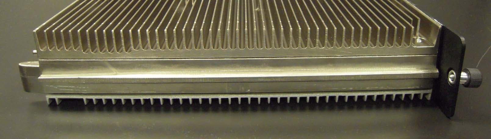
M External Photos Exhibit Global Telecom Solutions Sector FCC ID: IHET6EK1 FCC Filing – SC480 1X-EVDO with cPAs @ 1.9 GHz CDMA BTS Page 1 of 9 External Photos Exhibit SC480 1X-EVDO with cPAs @ 1.9 GHz CDMA BTS Number Description 1 Front View Compact 2 Rear View Compact 3 Left Side View Compact 4 Right Side View Compact 5 Top View Compact 6 Front View cPA 7 Rear View cPA 8 Rear View cPA (No cover) M External Photos Exhibit Global Telecom Solutions Sector FCC ID: IHET6EK1 FCC Filing – SC4801X-EVDO with cPAs @ 1.9 GHz CDMA BTS Page 2 of 9 External Photos Exhibit Compact – Front View M External Photos Exhibit Global Telecom Solutions Sector FCC ID: IHET6EK1 FCC Filing – SC480 1X-EVDO with cPAs @ 1.9 GHz CDMA BTS Page 3 of 9 External Photos Exhibit Compact – Rear View M External Photos Exhibit Global Telecom Solutions Sector FCC ID: IHET6EK1 FCC Filing – SC480 1X-EVDO with cPAs @ 1.9 GHz CDMA BTS Page 4 of 9 External Photos Exhibit Compact – Left Side View M External Photos Exhibit Global Telecom Solutions Sector FCC ID: IHET6EK1 FCC Filing – SC480 1X-EVDO with cPAs @ 1.9 GHz CDMA BTS Page 5 of 9 External Photos Exhibit Compact – Right Side View M External Photos Exhibit Global Telecom Solutions Sector FCC ID: IHET6EK1 FCC Filing – SC480 1X-EVDO with cPAs @ 1.9 GHz CDMA BTS Page 6 of 9 External Photos Exhibit Compact – Top View M External Photos Exhibit Global Telecom Solutions Sector FCC ID: IHET6EK1 FCC Filing – SC480 1X-EVDO with cPAs @1.9 GHz CDMA BTS Page 7 of 9 External Photos Exhibit cPA – Front View M External Photos Exhibit Global Telecom Solutions Sector FCC ID: IHET6EK1 FCC Filing – SC480 1X-EVDO with cPAs @ 1.9 GHz CDMA BTS Page 8 of 9 External Photos Exhibit cPA - Rear View M External Photos Exhibit Global Telecom Solutions Sector FCC ID: IHET6EK1 FCC Filing – SC480 1X-EVDO with cPAs @ 1.9 GHz CDMA BTS Page 9 of 9 External Photos Exhibit cPA - Front View (no cover)
ID Label/Location Info
IHET6EK1 US: IHEDENANSC4801XDO Applicant: Motorola FCC ID IHET6EK1 Applicant: Motorola FCC ID IHET6EK1 FCC LABELS placed here with front panels removed
Internal Photos
M Internal Photos Exhibit Global Telecom Solutions Sector FCC ID: IHET6EK1 FCC Filing – SC480 1X-EVDO with cPAs @ 1.9 GHz CDMA BTS Page 1 of 18 Internal Photos Exhibit CMPC – Front View M Internal Photos Exhibit Global Telecom Solutions Sector FCC ID: IHET6EK1 FCC Filing – SC480 1X-EVDO with cPAs @ 1.9 GHz CDMA BTS Page 2 of 18 Internal Photos Exhibit CMPC - Rear View M Internal Photos Exhibit Global Telecom Solutions Sector FCC ID: IHET6EK1 FCC Filing – SC480 1X-EVDO with cPAs @ 1.9 GHz CDMA BTS Page 3 of 18 Internal Photos Exhibit Group Line Interface (GLI3) - Front View M Internal Photos Exhibit Global Telecom Solutions Sector FCC ID: IHET6EK1 FCC Filing – SC480 1X-EVDO with cPAs @ 1.9 GHz CDMA BTS Page 4 of 18 Internal Photos Exhibit Group Line Interface (GLI3) - Rear View M Internal Photos Exhibit Global Telecom Solutions Sector FCC ID: IHET6EK1 FCC Filing – SC480 1X-EVDO with cPAs @ 1.9 GHz CDMA BTS Page 5 of 18 Internal Photos Exhibit BBX-1X - Front View M Internal Photos Exhibit Global Telecom Solutions Sector FCC ID: IHET6EK1 FCC Filing – SC480 1X-EVDO with cPAs @ 1.9 GHz CDMA BTS Page 6 of 18 Internal Photos Exhibit BBX-1X - Rear View M Internal Photos Exhibit Global Telecom Solutions Sector FCC ID: IHET6EK1 FCC Filing – SC480 1X-EVDO with cPAs @ 1.9 GHz CDMA BTS Page 7 of 18 Internal Photos Exhibit MCC-1X - Front View M Internal Photos Exhibit Global Telecom Solutions Sector FCC ID: IHET6EK1 FCC Filing – SC480 1X-EVDO with cPAs @ 1.9 GHz CDMA BTS Page 8 of 18 Internal Photos Exhibit MCC-1X - Rear View M Internal Photos Exhibit Global Telecom Solutio…
Text truncated - open the document above for the full version.
Contact Information
Applicant
Steve Mitchell
Technical Contact
MotorolaTerry Schwenk
[email protected]847-435-0780
1475 W. Shure Drive · Arlington Heights, Illinois · United States
Non-Technical Contact
MotorolaFrancisco Avalos
[email protected]847-435-9743
Test Firm
Underwriters Laboratories Inc.Rick Titus
Technical Specifications
| # | Rule Parts | Frequency Range | Power Output | Emission | Tolerance |
|---|---|---|---|---|---|
| 1 | 24E | 1.93 GHz - 1.99 GHz | 20 W | 1M30F9W | 1.5000000000 ppm |
Other Applications from Nokia Solutions and Networks
IHET4KJ1
Apr 28, 2010LTE 700 MHz Public Safety Base Station Transceiver
Equipment Class
TNB - Licensed Non-Broadcast Station Transmitter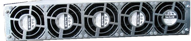
IHET5GX1
Oct 14, 2007UBS CDMA XMI Transceiver at 800 MHz
Equipment Class
TNB - Licensed Non-Broadcast Station Transmitter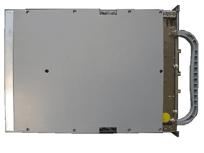
IHET6HG1
Sep 12, 2007CDMA Base Station
Equipment Class
PCB - PCS Licensed Transmitter
IHET7HN1
Jul 17, 20072.5 GHz Diversity Access Point
Equipment Class
TNB - Licensed Non-Broadcast Station Transmitter
IHET7GT1
Jan 14, 20072.5GHz DIVERSITY ACCESS POINT
Equipment Class
TNB - Licensed Non-Broadcast Station Transmitter