IHET6YR1SC4812T 1.9GHz CDMA BTS
Nokia Solutions and Networks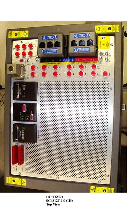
Click to zoom
Application Details
- Equipment Class
- TNB - Licensed Non-Broadcast Station Transmitter
- Date of Grant
- Dec 21, 1998
- Application Purpose
- Original Equipment
- Date of Application
- Oct 14, 1998
- Equipment Note
- SC4812T 1.9GHz CDMA BTS
- Frequency Range
- 1931.25000000 - 1988.75000000
- Company
- Nokia Solutions and Networks
- Country
- United States
Documents & Files
Document Text
Text extracted from the exhibit documents filed with the FCC. Open a document above to read the original.
Users Manual
FCC Filing - SC4812T @1.9 GHz CDMA BTS Frame Cellular Infrastructure Group FCC ID: IHET6YR1 EXHIBIT #10 BTS OPTIMIZATION PROCEDURE NOTE: Documentation for the SC4812T @1.9 GHz CDMA BTS Frame is currently under development and is similar to the optimization manual for FCC ID: IHET5XS1. Please refer to that package for this bulky document.
Cover Letter(s)
FCC Filing - SC4812T @1.9 GHz CDMA BTS Frame Cellular Infrastructure Group October 09, 1998 Federal Communications Commission Authorization & Evaluation Division 7435 Oakland Mills Rd. Columbia, Maryland 21046 Re: Application for Cellular Transceiver Certification Gentlemen: Motorola Inc., 5555 N. Beach Street, Fort Worth, Texas 76137, herein submits: Check Number: 636874 in the amount of $610.00, Application for Equipment Authorization (FCC Form 731) and Exhibits, for Certification of a PCS Cellular Transceiver, FCC ID: IHET6YR1. Motorola is also the manufacturer of this equipment. Motorola requests that the following Exhibits of this filing be kept confidential: Exhibit #5A MPC6 - Multicoupler Preselector Card Schematic Diagram Exhibit #5BGLI2 - Group Line Interface Card Schematic Diagram Exhibit #5CBBX2- Broadband Transceiver Card Schematic Diagram Exhibit #5DMCC x 24E - Multi Channel CDMA Card Schematic Diagram Exhibit #5E CCD - CDMA Clock Distribution Card Schematic Diagram Exhibit #5F CSM2 - Clock Synchronization Module w/GPS Schematic Diagram Exhibit #5G LPA - Linear Power Amplifier Schematic Diagram Exhibit #5H CIO - Combiner Input/Output Card Schematic Diagram Exhibit #5I Switch Card Schematic Diagram Exhibit #5J HSO - High Stability Oscillator Schematic Diagram Exhibit #5K SPAN I/O Schematic Diagrams Exhibit #5L SITE I/O Schematic Diagrams Exhibit #5M RGD-Remote GPS Distribution Schematic Diagram The confidential portions have been identified as such on the Uploading Exhibits Form. The filing fee includes $135.00, the amount for a confidential filing. page 1 of 2
External Photos
FCC Filing - SC4812T @1.9 GHz CDMA BTS Frame APPLICANT: MOTOROLA TRANSCEIVER TYPE: IHET6YR1 SC4812T @1.9 GHz CDMA BTS Frame EXHIBIT #3 List of External Photographs NO. PHOTOGRAPH 01Front View Door Closed 02Front View Door Open 03Rear View with Panel 04Rear View without Panel 05Left Side View 06Right Side View 07Top View
ID Label/Location Info
APPLICANT: MOTOROLAFCC ID: IHET6YR1 EQUIPMENT NAMEPLATE PER CFR., Title 47, Part 2.925 Model No. ______________ MOTOROLA FCC ID: Serial No. ____________ COMPLIES WITH PART 68, FCC RULES FCC REG. NO. IHEUSA-23899-DT-N REN: 0.3B USOC: RJ11C Graphics to be black A name plate of this type, or one similar to it, will be affixed to every base station. This label is permanent, indelible, and tamper evident. Bar Coding IHET6YR1
Internal Photos
FCC Filing - SC4812T @1.9 GHz CDMA BTS Frame APPLICANT: MOTOROLA TRANSCEIVER TYPE: IHET6YR1 SC4812T @1.9 GHz CDMA BTS Frame EXHIBIT #9 List of Internal Photographs NO. PHOTOGRAPH 01MPC Front 02MPC Back 03GLI2 Front 04GLI2 Back 05BBX2 with Cover 06BBX2 without Cover 07BBX2 Back 08MCC x 24E Front 09MCC x 24E Back 10CCD Front 11CCD Back 12CCD Front with Cover 13CSM2 Front 14CSM2 Back 15LPA Front 16LPA Back 17LPA without Cover 18Power Supply Front 19Power Supply Back 20CIO Front 21CIO Back 22Switch Card Front 23Switch Card Back 24AMR Front 25AMR Back 26HSO Front 27HSO Back 28SPAN I/O Front 29SPAN I/O Back
Operational Description
FCC Filing - SC4812T @1.9 GHz CDMA BTS Frame Cellular Infrastructure Group FCC ID: IHET6YR1 EXHIBIT #8 HARDWARE INSTALLATION NOTE: Documentation for the SC4812T @1.9 GHz CDMA BTS Frame is currently under development and is similar to the manual for FCC ID: IHET5XS1. Please refer to that package for installation manual.
Operational Description
FCC Filing - SC4812T @1.9 GHz CDMA BTS Frame Cellular Infrastructure Group FCC ID: IHET6YR1 EXHIBIT #11A DESCRIPTIVE INFORMATION FCC Filing- SC4812 @1.9 GHz CDMA BTS Frame1 DESCRIPTIVE INFORMATION FCC FILING FOR SC4812T @1.9 GHz CDMA BTS FRAME The Information in this exhibit is in accordance with the FCC Rules and Regulations, Vol. II, Part 2, Subpart J. Sections 2.983 through 2.999 are addressed. Section 2.983 (a)Name of Applicant and Manufacturer: MOTOROLA Section 2.983 (b) Identification of Equipment: IHET6YR1 Section 2.983 (c) Quantity Production: Quantity Production is Planned. Section 2.983 (d) Technical Description This Transmitter is intended for use in the Public Cellular Radio Telecommunications Service and is designed in compliance with the FCC Rules and Regulations Title 47, Part 24(E).This transmitter is capable of spread spectrum (CDMA) operation, and allows up to 64 Walsh codes to support Pilot, Sync, Paging and Traffic channels. (1) Types of Emissions This equipment will be capable of operation using wide band spread spectrum techniques employing Direct Sequence Code Division Multiple Access (DS-CDMA) digital communication techniques. For this transmitter, the emission designator is 1M25F9W (per FCC Part 2.201, subpart C). (2)Frequency Range This transmitter operates within the 1930 to 1990 MHz Band (per FCC Part 24). This base station will support CDMA operations on channel numbers 25 through 1175 (1931.25 MHz - 1988.75 MHz. (3) Range of Operating Power The rated maximum average power out of the SC4812T @1.9 GHz CDMA BTS Frame is 44.88 W (46.5 dBm). However, in CDMA the actual power output is based on the number of traffic channels in operation. The minimum power occurs when only a pilot signal is present. The maximum power occurs when a pilot along with synchronization, paging, and traffic channels are present. For a typical system setup, the theoretical difference between minimum power and maximum power is 8dB. The output power is variable in 0.25 dB steps. The range is 12 dB. FCC Filing- SC4812 @1.9 GHz CDMA BTS Frame2 (3) Range of Operating Power (cont.) In addition, the dynamics of a CDMA system allow for what is called “cell breathing”. This allows an operator to vary the range of a cell by controlling the power of the pilot signal. (4) Maximum Power Limits The peak output power of a base station transmitter may not exceed 100 Watts as defined in Part 24.232 (5)Applied voltages and currents into the final transistor elements of the transmitter output: In the CDMA system, the applied voltages and currents into the final transistor elements SRF7042X4 for 44.88 W output: Drain 27.7 VDC Drain Current 1.0 AMPS x 3 Gate Voltage 4 VDC (6) Function of Each Active Device Refer to Exhibit #11B. (7) Complete Circuit Diagrams Refer to Exhibits #5A through #5M. (8) Instruction/Installation Manual Refer to Exhibit #8 (9) Tune-Up/Optimization Procedure Refer to Exhibit #10 FCC Filing- SC4812 @1.9 GHz CDMA BTS Frame3 (10) Means for Frequency Stabilization Refer to Exhibit #6F The Clock Synchronization Module (CSM/CSM2) provides clock and time signals for an SC4812T @1.9 GHz CDMA BTS Frame. In addition, it provides the primary source, a 3 MHz clock, for the transmit synthesizer in the Broadband Transceiver. The CSM/CSM2 relies on a GPS receiver, either riding piggyback onto the CSM/CSM2 card or remotely located in an integrated package with the GPS antenna as the primary time reference for the ovenized oscillator. Two types of redundancy are provided: 1)Dual CSM/CSM2 cards provide redundancy in case of primary CSM/CSM2 failure. 2) Redundancy is also provided by either a High Stability Oscillator (HSO) or a Low Frequency Reference (LFR), such as a Loran C receiver, residing in a separate slot. The HSO is provided in case of GPS system failure. The CSM/CSM2 uses the received signals as a reference to provide the required clock for the site. The CSM/CSM2 distributes CDMA time, a 19.6608 MHz clock, and a two second synchronization pulse every even second of universal time to the CDMA Clock Distribution (CCD) Cards . The CSM/CSM2 is also responsible for configuration and management of the GPS and LFR systems. CSM/CSM2 software determines on a site basis what the GPS and LFR configurations should be. For future Commercial CDMA systems, GPS and LFR configuration information could optionally be downloaded to the CSM/CSM2 from the GLI2. The CSM/CSM2 is managed by the GLI2. The High Stability Oscillator (HSO) or Low Frequency Time Reference (LFR) is used to provide a stable time reference in case of a GPS system failure or shutdown. The output of the LFR card is routed to the CSM/CSM2 cards, which derive the appropriate time references for the Frame. The current LFR is a LoranC receiver. In areas where LoranC is unavailable, the HSO may be used. FCC Filing- SC4812 @1.9 GHz CDMA BTS Frame4 (11) Means for Attenuation of Spurious Emissions Refer to Exhibit #6C Bandpass filters are employed in the transmit RF circuit to attenuate far out spurious emissions. The filter used here is of an air dielectric cavity resonator type. The baseband employs a discrete L-C 7-pole elliptic filter. This filter is used to attenuate sideband noise and close in spurious emissions. In addition, suppression of spurious radiation is obtained by proper shielding techniques. Means for Limiting Modulation Refer to Exhibits #6B and #6F In a CDMA system, the input signal (voice for example) is sampled and coded in a vocoder. This signal is then spread to 1.23 MHz by a pseudo-random spreading code. This spreading code sets the bandwidth of the spread-spectrum signal. If more than one signal is in operation (i.e. more than one voice channel), then the two signals are simply layered one atop the other within the 1.23 MHz band. So, to some extent, the bandwidth of the transmitted signal is limited by the chip rate of the PN spreading code. Primary limiting of the CDMA signal bandwidth is accomplished by the use of a programma…
Text truncated - open the document above for the full version.
Parts List/Tune Up Info
FCC Filing - SC4812T @1.9 GHz CDMA BTS Frame Cellular Infrastructure Group FCC ID: IHET6YR1 EXHIBIT #8 HARDWARE INSTALLATION NOTE: Documentation for the SC4812T @1.9 GHz CDMA BTS Frame is currently under development and is similar to the manual for FCC ID: IHET5XS1. Please refer to that package for installation manual.
Test Report
APPLICANT: MOTOROLA TRANSCEIVER TYPE: IHET6YR1 SC4812T @1.9 GHz CDMA BTS Frame EXHIBIT #6 Test Report Index Exhibit # Description 6ASummary of RF Measurements 6BModulation Characteristics 6CSpurious & Harmonic Emissions Radiated 6DSpurious & Harmonic Emissions Conducted 6EOccupied Bandwidth 6FFrequency Stability FCC Filing - SC4812T @1.9 GHz CDMA BTS Frame Cellular Infrastructure Group FCC ID: IHET6YR1 EXHIBIT #6A SUMMARY OF RF MEASUREMENTS FCC Filing - SC4812T @1.9 GHz CDMA BTS Frame Cellular Infrastructure Group FCC ID: IHET6YR1 EXHIBIT #6B MODULATION CHARACTERISTICS FCC Filing - SC4812T @1.9 GHz CDMA BTS Frame Cellular Infrastructure Group FCC ID: IHET6YR1 EXHIBIT #6C SPURIOUS & HARMONIC EMISSIONS RADIATED FCC Filing - SC4812T @1.9 GHz CDMA BTS Frame Cellular Infrastructure Group FCC ID: IHET6YR1 EXHIBIT #6D SPURIOUS & HARMONIC EMISSIONS CONDUCTED NOTE: The plots for conducted spurious and harmonic emissions are measured in peak mode. The higher (than 44.88 watts) levels measured in peak mode are expected, due to typical CDMA peak to average performance. The average power level was set to 44.88 watts using an HP438A power meter. FCC Filing - SC4812T @1.9 GHz CDMA BTS Frame Cellular Infrastructure Group FCC ID: IHET6YR1 SPURIOUS & HARMONIC EMISSIONS CONDUCTED EMISSIONS IN THE 1 MHz BW LOCATED 1 MHz AWAY FROM THE LOWER EDGE OF THE FREQUENCY BLOCK AT 1928.5 MHz Maximum Power CDMA TX @ 46.5 dBm CH. 25 at (1931.25 MHz) NOTE: The configuration which created the following plots had 30.0 dB of attenuation from the SC4812T 1.9 GHz CDMA BTS Frame output to the spectrum analyzer input. FCC Filing - SC4812T @1.9 GHz CDMA BTS Frame Cellular Infrastructure Group FCC ID: IHET6YR1 SPURIOUS & HARMONIC EMISSIONS CONDUCTED EMISSIONS IN THE 1 MHz BW LOCATED 1 MHz AWAY FROM THE UPPER EDGE OF THE FREQUENCY BLOCK AT 1991.5 MHz Maximum Power CDMA TX @ 46.5 dBm CH. 1175 at (1988.75 MHz) NOTE: The configuration which created the following plots had 30.0 dB of attenuation from the SC4812T 1.9 GHz CDMA BTS Frame output to the spectrum analyzer input. FCC Filing - SC4812T @1.9 GHz CDMA BTS Frame Cellular Infrastructure Group FCC ID: IHET6YR1 SPURIOUS & HARMONIC EMISSIONS CONDUCTED EMISSIONS IN THE 1 MHz BW LOCATED 1 MHz AWAY FROM THE LOWER EDGE OF THE FREQUENCY BLOCK AT 1928.5 MHz Minimum Power CDMA TX @ 23.5 dBm CH. 25 at (1931.25 MHz) NOTE: The configuration which created the following plots had 30.0 dB of attenuation from the SC4812T 1.9 GHz CDMA BTS Frame output to the spectrum analyzer input. FCC Filing - SC4812T @1.9 GHz CDMA BTS Frame Cellular Infrastructure Group FCC ID: IHET6YR1 SPURIOUS & HARMONIC EMISSIONS CONDUCTED EMISSIONS IN THE 1 MHz BW LOCATED 1 MHz AWAY FROM THE UPPER EDGE OF THE FREQUENCY BLOCK AT 1991.5 MHz Minimum Power CDMA TX @ 23.5 dBm CH. 1175 at (1988.75 MHz) NOTE: The configuration which created the following plots had 30.0 dB of attenuation from the SC4812T 1.9 GHz CDMA BTS Frame output to the spectrum analyzer input. FCC Filing - SC4812T @1.9 GHz CDMA BTS Frame Cellular Infrastructure Group FCC ID: IHET6YR1 EXHIBIT #6E OCCUPIED BANDWIDTH NOTE: The occupied bandwidth plots are measured in a 30 kHz resolution bandwidth. The following formula is used to obtain the correct zero dB reference point relative to the bandwidth of the 1.2288 MHz CDMA signal. Power(measured in 30 kHz bandwidth) + 10 log 1.2288MHz 30kHz Example: 30.49 dBm + 16.12 dB≈ 46.61 dBm The output power was set to 44.88 Watts using an HP438A power meter. FCC Filing - SC4812T @1.9 GHz CDMA BTS Frame Cellular Infrastructure Group FCC ID: IHET6YR1 EXHIBIT #6F FREQUENCY STABILITY
Test Setup Photos
MOTOROLA FCC Radiated Testing * *Note: Equipment calibration is in accordance with ISO 9000
Contact Information
Applicant
Steve Mitchell
Technical Contact
Motorola Cellular Infrastructure GroupClifford H Critchett
[email protected]817-245-6122
5555 North Beach Street, 7C · Fort Worth, Texas · United States
Non-Technical Contact
Motorola Cellular Infrastructure GroupMelissa A Van Drie
[email protected]817-245-6039
Technical Specifications
| # | Rule Parts | Frequency Range | Power Output | Emission | Tolerance |
|---|---|---|---|---|---|
| 1 | 24E | 1.93 GHz - 1.99 GHz | 44.88 W | 1M25F9W | 1.5000000000 ppm |
Other Applications from Nokia Solutions and Networks
IHET4KJ1
Apr 28, 2010LTE 700 MHz Public Safety Base Station Transceiver
Equipment Class
TNB - Licensed Non-Broadcast Station Transmitter
IHET5GX1
Oct 14, 2007UBS CDMA XMI Transceiver at 800 MHz
Equipment Class
TNB - Licensed Non-Broadcast Station Transmitter
IHET6HG1
Sep 12, 2007CDMA Base Station
Equipment Class
PCB - PCS Licensed Transmitter
IHET7HN1
Jul 17, 20072.5 GHz Diversity Access Point
Equipment Class
TNB - Licensed Non-Broadcast Station Transmitter
IHET7GT1
Jan 14, 20072.5GHz DIVERSITY ACCESS POINT
Equipment Class
TNB - Licensed Non-Broadcast Station Transmitter