IMK-8455802.11a Cardbus
Proxim Inc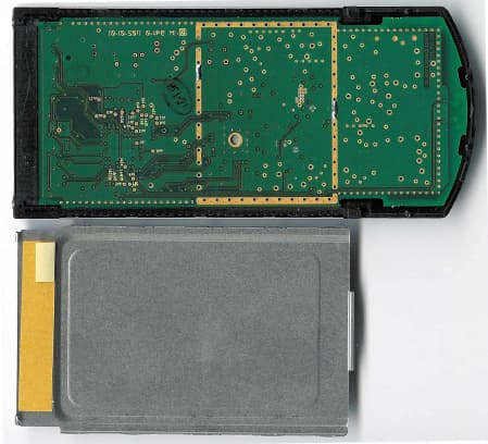
Click to zoom
Application Details
- Equipment Class
- NII - Unlicensed National Information Infrastructure TX
- Date of Grant
- Dec 05, 2002
- Application Purpose
- Original Equipment
- Date of Application
- May 16, 2002
- Equipment Note
- 802.11a Cardbus
- Frequency Range
- 5725.00000000 - 5825.00000000
- Company
- Proxim Inc
- Country
- United States
Documents & Files
Document Text
Text extracted from the exhibit documents filed with the FCC. Open a document above to read the original.
Users Manual
Harmony Harmony 802.11a Network Adapter User's Guide 2 Copyright © 2002 Proxim Corporation, Sunnyvale, CA. All rights reserved. Covered by one or more of the following U.S. patents: 5,231,634; 5,875,179; 6,006,090. This user’s guide and the software described in it are copyrighted with all rights reserved. No part of this publication may be reproduced, transmitted, transcribed, stored in a retrieval system, or translated into any language in any form by any means without the written permission of Proxim Corporation. Trademarks Harmony, the Harmony logo, 2X, Proxim, and the Proxim logo are trademarks of Proxim Corporation. All other trademarks are the property of their respective owners. Limited Warranty, Disclaimer, Limitation Of Liability For a period of three (3) years from the date of purchase by the retail customer, Proxim warrants the Harmony 802.11a CardBus Cards (Models 8450 and 8455) and the Harmony 802.11a PCI Card (Model 8150) against defects in materials and workmanship. Proxim will not honor this warranty if there has been any attempt to tamper with or remove the product’s external foil label. This warranty does not cover and Proxim will not be liable for any damage or failure caused by misuse, abuse, acts of God, accidents, or other causes beyond Proxim’s control, or claim by any entity other than the original purchaser. If, after inspection, Proxim determines there is a defect, Proxim will repair or replace the Harmony 802.11a network adapter at no cost to you. To return defective merchandise to Proxim, please call Proxim Technical Support at 1-408-731-2640 to obtain a Return Merchandise Authorization (RMA) number. In no event shall Proxim Corporation be responsible or liable for any damages arising: • From the use of the product • From the loss of use, revenue or profit of the product • As a result of any event, circumstance, action, or abuse beyond the control of Proxim Corporation Whether such damages be direct, indirect, consequential, special, or otherwise and whether such damages are incurred by the person to whom this warranty extends or a third party. Warranty Return Policy If you have a problem with a Harmony 802.11a CardBus Card (Model 8450 or 8455) or a Harmony 802.11a PCI Card (Model 8150), please call Proxim Technical Support at 1-408-731-2640. Proxim Technical Support will assist with resolving any technical difficulties you may have with your Proxim product. After calling Proxim Technical Support, if your product is found to be defective, you may return the product to Proxim after obtaining an RMA (Return Merchandise Authorization) number. The product must be returned in its original packaging. The RMA number should be clearly marked on the outside of the box. Proxim cannot be held responsible for any product returned without an RMA number, and no product will be accepted without an RMA number. FCC WARNING This equipment has been tested and found to comply with the limits for a Class B digital device, pursuant to Part 15 of the FCC Rules. These limits are designed to provide reasonable protection against harmful interference in a residential installation. This equipment generates, uses, and can radiate radio frequency energy and, if not installed and used in accordance with the instructions, may cause harmful interference to radio communications. However, there is no guarantee that interference will not occur in a particular installation. If this equipment does cause harmful interference to radio or television reception, which can be determined by turning the equipment off and on, the user is encouraged to try to correct the interference by one or more of the following measures: • Reorient or relocate the receiving antenna. • Increase the separation between the equipment and the receiver. • Connect the equipment into an outlet on a circuit different from that which the receiver is connected. • Consult the dealer or an experienced radio/TV technician for help. This device complies with part 15 of the FCC Rules. Operation is subject to the following two conditions: (1) This device may not cause harmful interference, and (2) this device must accept any interference received, including interference that may cause undesired operation. Harmony 802.11a Network Adapter User’s Guide Part # 2050.0471 Rev. C -- D1 3 Declaration of Conformity Déclaration de Conformité Konformitätserklärung The Manufacturer:Proxim Europe B.V. Le Constructeur: Der Hersteller: Address:Prins Bernhardplein 200 Addresse: 1097 JB, P.O. Box 94071, Addresse: 1090 GB Amsterdam, The Netherlands Declares that the Product: Déclare que le Produit: Erklärt, dass das Produkt: Type:Harmony 802.11a Models:8450 CardBus Card 8150 PCI Card meets the essential requirements according to article 3 of the following EC-Directive: est conforme aux exigencies essentielles d’article 3 de la Directive CE: die grundlegenden Anforderungen gemäâ Artikel 3 der nachstehenden EU-Richtlinie erfült: Directive 1999/5/EC of the European Parliament and of the Council of 09 March 1999 relating to Radio and Telecommunications Terminal Equipment (R&TTE), including the mutual recognition of their conformity. Directive 1999/5/EC du Parlement Europeen et du Conseil du 09 mache 1999 concernant les radio et equipments terminaux de telecommunications, incluant la reconnaissance mutuelle de leur conformite. Richtlinie 1999/5/EG des Europäischen Parlaments und des Rates vom 09. März 1999 über Funkanlagen und Telekommunikationsendeinrichtungen und die gegenseitige Anerkennung ihrer Konformität. and that the following harmonized standards have been applied: et que les standards marmonises suivants ont ete appliqués: und dass die folgenden harmonisierten Normen angewandt wurden: EN301893-V1.1.1 / January 2001 EN301489-17 V1.1.1 / September 2000 EN60950 / December 2000 Equipment Class Identifier This Product is a Class-2 under the scope of the R&TTE. Be aware that certain countries use other frequencies or have special restrictions of use. Th…
Text truncated - open the document above for the full version.
Users Manual
Harmony Harmony 802.11a Network Adapter User's Guide 2 Copyright © 2002 Proxim Corporation, Sunnyvale, CA. All rights reserved. Covered by one or more of the following U.S. patents: 5,231,634; 5,875,179; 6,006,090. This user’s guide and the software described in it are copyrighted with all rights reserved. No part of this publication may be reproduced, transmitted, transcribed, stored in a retrieval system, or translated into any language in any form by any means without the written permission of Proxim Corporation. Trademarks Harmony, the Harmony logo, 2X, Proxim, and the Proxim logo are trademarks of Proxim Corporation. All other trademarks are the property of their respective owners. Limited Warranty, Disclaimer, Limitation Of Liability For a period of three (3) years from the date of purchase by the retail customer, Proxim warrants the Harmony 802.11a CardBus Cards (Models 8450 and 8455) and the Harmony 802.11a PCI Card (Model 8150) against defects in materials and workmanship. Proxim will not honor this warranty if there has been any attempt to tamper with or remove the product’s external foil label. This warranty does not cover and Proxim will not be liable for any damage or failure caused by misuse, abuse, acts of God, accidents, or other causes beyond Proxim’s control, or claim by any entity other than the original purchaser. If, after inspection, Proxim determines there is a defect, Proxim will repair or replace the Harmony 802.11a network adapter at no cost to you. To return defective merchandise to Proxim, please call Proxim Technical Support at 1-408-731-2640 to obtain a Return Merchandise Authorization (RMA) number. In no event shall Proxim Corporation be responsible or liable for any damages arising: • From the use of the product • From the loss of use, revenue or profit of the product • As a result of any event, circumstance, action, or abuse beyond the control of Proxim Corporation Whether such damages be direct, indirect, consequential, special, or otherwise and whether such damages are incurred by the person to whom this warranty extends or a third party. Warranty Return Policy If you have a problem with a Harmony 802.11a CardBus Card (Model 8450 or 8455) or a Harmony 802.11a PCI Card (Model 8150), please call Proxim Technical Support at 1-408-731-2640. Proxim Technical Support will assist with resolving any technical difficulties you may have with your Proxim product. After calling Proxim Technical Support, if your product is found to be defective, you may return the product to Proxim after obtaining an RMA (Return Merchandise Authorization) number. The product must be returned in its original packaging. The RMA number should be clearly marked on the outside of the box. Proxim cannot be held responsible for any product returned without an RMA number, and no product will be accepted without an RMA number. FCC WARNING This equipment has been tested and found to comply with the limits for a Class B digital device, pursuant to Part 15 of the FCC Rules. These limits are designed to provide reasonable protection against harmful interference in a residential installation. This equipment generates, uses, and can radiate radio frequency energy and, if not installed and used in accordance with the instructions, may cause harmful interference to radio communications. However, there is no guarantee that interference will not occur in a particular installation. If this equipment does cause harmful interference to radio or television reception, which can be determined by turning the equipment off and on, the user is encouraged to try to correct the interference by one or more of the following measures: • Reorient or relocate the receiving antenna. • Increase the separation between the equipment and the receiver. • Connect the equipment into an outlet on a circuit different from that which the receiver is connected. • Consult the dealer or an experienced radio/TV technician for help. This device complies with part 15 of the FCC Rules. Operation is subject to the following two conditions: (1) This device may not cause harmful interference, and (2) this device must accept any interference received, including interference that may cause undesired operation. Harmony 802.11a Network Adapter User’s Guide Part # 2050.0471 Rev. -- 8455 D6 3 Declaration of Conformity Déclaration de Conformité Konformitätserklärung The Manufacturer:Proxim Europe B.V. Le Constructeur: Der Hersteller: Address:Prins Bernhardplein 200 Addresse: 1097 JB, P.O. Box 94071, Addresse: 1090 GB Amsterdam, The Netherlands Declares that the Product: Déclare que le Produit: Erklärt, dass das Produkt: Type:Harmony 802.11a Models:8450 CardBus Card 8150 PCI Card meets the essential requirements according to article 3 of the following EC-Directive: est conforme aux exigencies essentielles d’article 3 de la Directive CE: die grundlegenden Anforderungen gemäâ Artikel 3 der nachstehenden EU-Richtlinie erfült: Directive 1999/5/EC of the European Parliament and of the Council of 09 March 1999 relating to Radio and Telecommunications Terminal Equipment (R&TTE), including the mutual recognition of their conformity. Directive 1999/5/EC du Parlement Europeen et du Conseil du 09 mache 1999 concernant les radio et equipments terminaux de telecommunications, incluant la reconnaissance mutuelle de leur conformite. Richtlinie 1999/5/EG des Europäischen Parlaments und des Rates vom 09. März 1999 über Funkanlagen und Telekommunikationsendeinrichtungen und die gegenseitige Anerkennung ihrer Konformität. and that the following harmonized standards have been applied: et que les standards marmonises suivants ont ete appliqués: und dass die folgenden harmonisierten Normen angewandt wurden: EN301893-V1.1.1 / January 2001 EN301489-17 V1.1.1 / September 2000 EN60950 / December 2000 Equipment Class Identifier This Product is a Class-2 under the scope of the R&TTE. Be aware that certain countries use other frequencies or have special restrictions of use.…
Text truncated - open the document above for the full version.
External Photos
Top Cover Assembled: Back Side of PCB and Back Cover: Back Side of PCB with Metal Cover: Completed Assembly Backside View
ID Label/Location Info
8455 Label Dimensions and Placement Top Label: Label Dimensions = 2.48 x 1.55 in. Label Material = .002in TC/249 White Mylar. Label Adhesive = Permanent Adhesive. Label Placement: Both top and bottom labels must be centered in the recessed area of the top and bottom metal covers. Bottom Label: (Same Dimension as top label)
Internal Photos
8455 Detailed Assembly Photos Inside View of Covers and PCB: Top Side PCB without Shield:
RF Exposure Info
SAR COMPLIANCE TESTING OF PROXIM CORPORATION MODEL 8455 (FCC ID# IMK-8455) CARDBUS CARD INSERTED INTO A LAPTOP COMPUTER May 14, 2002 Submitted to: Mr. Nathan Mueller Proxim Corporation 837 S. 500 W. # 200 Bountiful, UT 84010 Submitted by: Om P. Gandhi Professor of Electrical and Computer Engineering University of Utah 50 S Central Campus Dr., Rm. 3280 Salt Lake City, UT 84112-9206 SAR COMPLIANCE TESTING OF PROXIM CORPORATION MODEL 8455 (FCC ID# IMK-8455) CARDBUS CARD INSERTED INTO A LAPTOP COMPUTER I. Introduction The U.S. Federal Communications Commission (FCC) has adopted limits of human exposure to RF emissions from mobile and portable devices that are regulated by the FCC [1]. The FCC has also issued Supplement C (Edition 97-01) to OET Bulletin 65 [2] and a more recent version of the same [3] defining both the measurement and the computational procedures that should be followed for evaluating compliance of mobile and portable devices with FCC limits for human exposure to radiofrequency emissions. We have used the measurement procedure for SAR compliance testing of the Proxim Corporation wireless CardBus card ( FCC ID: IMK-8455 ) inserted into a laptop computer. A photograph of the unit with the CardBus card inserted into the laptop computer is given in Fig. 1. A picture of the Proxim Model 8455 CardBus card placed on the laptop is given in Fig. 2. The Proxim Model 8455 wireless CardBus card operates with a nominal conducted RF power output of 21 dBm (126 mW) for the frequency band 5.18-5.825 GHz. For SAR measurements, two configurations of the wireless PC relative to the experimental phantom have been used: a. Since the wireless PC may possibly be placed on a user's lap where the RF antennas would be the closest to the body, a planar phantom model with inside dimensions 12" × 16.5" (30.5 × 41.9 cm) and a base thickness of 2.0 ± 0.2 mm (recommended in [3]) was used for SAR measurements and the wireless PC cards mounted in a portable computer (as in Fig. 1) pressed against the bottom of this phantom (see Fig. 3). b . For a bystander, the "end-on" SAR value is obtained for the PC and the card edge at 90° to the flat phantom with a spacing of 2.5 cm (see Fig. 4). 2 II. Experimental Measurements of SAR Distribution As aforementioned, the measurements of the SAR distributions for the Proxim Corporation Model 8455 wireless CardBus Card inserted into a laptop computer (as in Fig. 1), both for the "above-lap" and "end-on" positions, were done with a planar rectangular box phantom made of acrylic of inside dimensions 12" × 16.5" (30.5 × 41.9 cm) shown in Figs. 3 and 4 for "above-lap" and "end-on" positions, respectively. This box phantom of external dimensions 13" × 17.5" (33 × 44.5 cm) is filled with a tissue-simulant fluid up to a depth of 15 cm. As recommended in [3], the base thickness of the box phantom is 2.0 ± 0.2 mm (0.079"). As seen in Figs. 3 and 4, a 1" thick Styrofoam block is used under the base, except for the region of the wireless laptop to prevent bending of the 2 mm thin base. Also for the SAR testing for the "end- on" position, a separation of 1" (2.5 cm) from the end of the PC card to the bottom of the planar phantom is used. The tissue-simulant fluid uses a composition developed at the University of Utah which consists of 68.0% water, 31.0% sugar and 1% HEC. For this composition, we have measured the dielectric properties using a Hewlett Packard (HP) Model 85070B Dielectric Probe in conjunction with HP Model 8720C Network Analyzer (50 MHz-20 GHz). The measured dielectric properties at a mid band frequency of 5.30 GHz are as follows: ε r = 48.5 ± 1.7 and σ = 5.40 ± 0.08 S/m. From the FCC Supplement C [3], we obtain the desired dielectric properties to simulate the body tissue at 5.30 GHz to be ε r = 48.9 and σ = 5.42 S/m. Thus, the measured properties for the body- simulant fluid are close to the desired values. III. Calibration of the E-Field Probe As in some previously reported SAR measurements at 6 GHz [4], we have calibrated the Narda Model 8021 Miniature Broadband Electric Field Probe of tip diameter 4 mm (0.4 to 10 GHz) using a rectangular waveguide WR 159 that was filled with this body-simulant fluid at 5.30 GHz. By comparing the electric fields expected in the tissue from the analytical expressions of the waveguide theory, we obtain a calibration factor of 2.98 (mW/kg)/μV. This is considerably 3 larger than calibration factors of 0.39 and 0.565 (mW/kg)/μV previously reported for the same probe at 835 MHz and 1900 MHz, respectively [5]. This is to be expected since the sensitivity of the diodes used for the Narda Model 8021 Miniature Broadband Electric Field Probe of tip diameter 4 mm is likely to diminish with frequency. I V . The Measured SAR Distributions The SAR distributions were determined using the automated SAR measurement system developed at the University of Utah [5]. As described in [5], this SAR measurement system has been validated using a number of wireless telephones at 835 and 1900 MHz, respectively. The highest SAR region for each of the measurement frequencies (5.18, 5.32, 5.745, and 5.825 GHz) was identified in the first instance by using a coarser sampling with a step size of 8.0 mm over three overlapping areas for a total scan area of 8.0 × 9.6 cm. After identifying the region of the highest SAR, the SAR distribution was measured with a resolution of 2 mm in order to obtain the peak 1 cm 3 or 1-g SAR. As given in [5], the SAR measurements are performed at 4, 6, 8, 10, 12 mm height from the bottom surface of the body-simulant fluid. The SARs thus measured were extrapolated to obtain values at 1, 3, 5, 7 and 9 mm height and used to obtain 1-g SARs. The uncertainty analysis of the University of Utah SAR measurement system is given in Appendix A. The combined standard uncertainty is ± 8.3%. The SAR distributions measured for transmit frequencies of 5.18, 5.32, 5.745, and 5.845 GHz are given in Tables 1-4 for the "above-lap" position and in Tables 5-8…
Text truncated - open the document above for the full version.
RF Exposure Info
PROJECT: 02U1295 PROXIM 8455 MPE CALCULATION for 1.5 dBi ANTENNA Formula used in the MPE Calculations: E^2/3770 = S, mW/cm2 Pwatts*Ggain = 10^(PdBm-30+GdBi)/10) E, V/m = (Pwatts*Ggain*30)^.5/d, meters d = ((Pwatts*G*30)/3770*S))^0.5 --------- (A) Since S (mW/cm2) =1.00 from 1.1310 Table 1 P (dBm) = 21.77 EUT output power G (dBi) = 1.50 EUT antenna gain Substitute these parameters into the A above, we have MPE safe distance d (cm) = 4.11 NOTE: For mobile or fixed location transmitters, minimum separation distance is 20 cm, even if calculations indicate MPE distance is less
RF Exposure Info
Proxim Model 8455 WideBand Top-Hat Antenna Linearity Analysis 8/19/02 Antenna tested: Small Scale WideBand Top-Hat Antenna, PN: C35-301, as mounted on a Proxim 8455 IEEE802.11a Wireless LAN adapter operating at: 5.15-5.35GHz, 5.725- 5.85GHz. Objective: To demonstrate in brief that radiation from the WB antenna is linear in the range of 50mW to 300mW. Antenna Construction: The WB antenna is a sheet metal stamped structure, solder attached to a printed transformer. Given the construction and comparisons to previously characterized antennas and simulations of similar structure, maximum power ratings are expected to exceed 1W CW before linearity is compromised. This analysis range is well within half of this theoretical maximum. Transmitter: The transmitter is an OFDM 5GHz radio, step controlled and linearized using internal calibration registers. Measurement methods: Both measurement sets were taken as peak measurements through an external LNA (in the linear region) connected to a spectrum analyzer. For ease of comparison, scaling was accomplished using adjustable attenuation on the conducted measurements so that both radiated and conducted measurements were taken in the same range (+/-2dB worst case) on the spectrum analyzer, centered and normalized at the conducted power output (measured at an on-board connector) of 20.66dBm. The receiver antenna is a commercially available half-wave dipole tuned for the test frequency. Max power for the dipole is 10W Conclusions: Though the entire curve is reasonably linear, the linear trend observed is the most critical piece of information in this analysis, demonstrating a predictable, linear relationship between the power into the antenna vs. what is actually radiated. In particular, in the range of 100mW to 126mW (20dBm to 21dBm) is sufficiently well behaved, following the general trend of linearity. WideBand 5GHz Top-Hat 13 14 15 16 17 18 19 20 21 22 23 24 25 12345678 Power out (dBm) conducted radiated
Test Report
FCC CFR47 PART 15 SUBPART E CERTIFICATION TEST REPORT FOR PROXIM INC 802.11a WIRELESS LAN CARDBUS CARD MODEL NUMBER: 8455 BRAND NAME: HARMONY OR SKYLINE 802.11a FCC ID: IMK-8455 REPORT NUMBER: 02U1295 ISSUE DATE: MAY 15, 2002 Prepared for PROXIM INC 510 DEGUIGNE DRIVE SUNNYVALE, CA 94085 USA Prepared by COMPLIANCE CERTIFICATION SERVICES 561F MONTEREY ROAD, MORGAN HILL, CA 95037, USA TEL: (408) 463-0885 FAX: (408) 463-0888 REPORT NO: 02U1295 DATE: MAY 15, 2002 EUT: 802.11a WIRELESS LAN CARDBUS CARD FCC ID: IMK-8455 Page 2 of 106 COMPLIANCE CERTIFICATION SERVICES DOCUMENT NO: CCSUP4031A 561F MONTEREY ROAD, MORGAN HILL, CA 95037 USA TEL: (408) 463-0885 FAX: (408) 463-0888 This report shall not be reproduced except in full, without the written approval of CCS. This document may be altered or revised by Compliance Certification Services personnel only, and shall be noted in the revision section of the document. TABLE OF CONTENT 1. TEST RESULT CERTIFICATION..........................................................................................3 2. EUT DESCRIPTION...............................................................................................................4 3. TEST METHODOLOGY.........................................................................................................4 4. TEST FACILITY.....................................................................................................................4 5. ACCREDITATION AND LISTING.........................................................................................4 5.1. Laboratory Accreditations and Listings................................................................................5 6. MEASURING INSTRUMENT CALIBRATION......................................................................6 6.1. Measurement Uncertainty...................................................................................................6 7. SUPPORT EQUIPMENT / TEST DIAGRAM.........................................................................7 8. APPLICABLE RULES AND BRIEF TEST RESULT..............................................................9 9. TEST SETUP, PROCEDURE AND RESULT........................................................................21 9.1. EMISSION BANDWIDTH.................................................................................................21 9.2. PEAK POWER................................................................................................................29 9.3. PEAK POWER SPECTRAL DENSITY................................................................................36 9.4. PEAK EXCURSION (PEAK – AVERAGE RATIO)..............................................................44 9.5. UNDESIRABLE EMISSION - BAND EDGE & DELTA (PEAK & AVERAGE)......................52 9.6. FREQUENCY STABILITY.................................................................................................62 9.7. UNDESIRABLE EMISSION..............................................................................................63 9.8. POWER LINE CONDUCTED EMISSION..........................................................................94 9.9. RADIATED EMISSION.....................................................................................................97 9.10. SETUP PHOTOS........................................................................................................103 REPORT NO: 02U1295 DATE: MAY 15, 2002 EUT: 802.11a WIRELESS LAN CARDBUS CARD FCC ID: IMK-8455 Page 3 of 106 COMPLIANCE CERTIFICATION SERVICES DOCUMENT NO: CCSUP4031A 561F MONTEREY ROAD, MORGAN HILL, CA 95037 USA TEL: (408) 463-0885 FAX: (408) 463-0888 This report shall not be reproduced except in full, without the written approval of CCS. This document may be altered or revised by Compliance Certification Services personnel only, and shall be noted in the revision section of the document. 1. TEST RESULT CERTIFICATION COMPANY NAME: PROXIM INC. 510 DEGUIGNE DRIVE SUNNYVALE, CA 94085 USA CONTACT PERSON: QUINN KUNZ TELPHONE NO: 801-292-2909 EXT 10 EUT DESCRIPTION: 802.11a WIRELESS LAN CARDBUS CARD MODEL NUMBER: 8455 DATE TESTED: MAY 7, 2002 – MAY 15, 2002 TYPE OF EQUIPMENT INTENTIONAL RADIATOR EQUIPMENT TYPE 5.15 – 5.35 GHz AND 5.725 – 5.850 GHz TRANSCEIVER MEASUREMENT PROCEDURE ANSI 63.4 / 1992, TIA/EIA 603 PROCEDURE CERTIFICATION FCC RULE CFR 47 PART 15.E Compliance Certification Services, Inc. tested the above equipment for compliance with the requirements set forth in CFR 47, PART 15, Subpart E. The equipment in the configuration described in this report, shows the measured emission levels emanating from the equipment do not exceed the specified limit. Note: This document reports conditions under which testing was conducted and results of tests performed. This document may not be altered or revised in any way unless done so by Compliance Certification Services and all revisions are duly noted in the revisions section. Any alteration of this document not carried out by Compliance Certification Services will constitute fraud and shall nullify the document. Approved & Released For CCS By: Tested By: MIKE HECKROTTE THU CHAN CHIEF ENGINEER SENIOR EMC ENGINEER COMPLIANCE CERTIFICATION SERVICES COMPLIANCE CERTIFICATION SERVICES REPORT NO: 02U1295 DATE: MAY 15, 2002 EUT: 802.11a WIRELESS LAN CARDBUS CARD FCC ID: IMK-8455 Page 4 of 106 COMPLIANCE CERTIFICATION SERVICES DOCUMENT NO: CCSUP4031A 561F MONTEREY ROAD, MORGAN HILL, CA 95037 USA TEL: (408) 463-0885 FAX: (408) 463-0888 This report shall not be reproduced except in full, without the written approval of CCS. This document may be altered or revised by Compliance Certification Services personnel only, and shall be noted in the revision section of the document. 2. EUT DESCRIPTION The Proxim 8455 is a high performance 802.11a-only WLAN client product intended for laptop applications. It operates in the 5.15 – 5.35 GHz and 5.275 – 5.850 GHz bands with a maximum average Tx output power of…
Text truncated - open the document above for the full version.
Test Report
REPORT NO: 02U1295 DATE: MAY 15, 2002 EUT: 802.11a WIRELESS LAN CARDBUS CARD FCC ID: IMK-8455 Page 27 of 106 COMPLIANCE CERTIFICATION SERVICES DOCUMENT NO: CCSUP4031A 561F MONTEREY ROAD, MORGAN HILL, CA 95037 USA TEL: (408) 463-0885 FAX: (408) 463-0888 This report shall not be reproduced except in full, without the written approval of CCS. This document may be altered or revised by Compliance Certification Services personnel only, and shall be noted in the revision section of the document. REPORT NO: 02U1295 DATE: MAY 15, 2002 EUT: 802.11a WIRELESS LAN CARDBUS CARD FCC ID: IMK-8455 Page 28 of 106 COMPLIANCE CERTIFICATION SERVICES DOCUMENT NO: CCSUP4031A 561F MONTEREY ROAD, MORGAN HILL, CA 95037 USA TEL: (408) 463-0885 FAX: (408) 463-0888 This report shall not be reproduced except in full, without the written approval of CCS. This document may be altered or revised by Compliance Certification Services personnel only, and shall be noted in the revision section of the document. REPORT NO: 02U1295 DATE: MAY 15, 2002 EUT: 802.11a WIRELESS LAN CARDBUS CARD FCC ID: IMK-8455 Page 29 of 106 COMPLIANCE CERTIFICATION SERVICES DOCUMENT NO: CCSUP4031A 561F MONTEREY ROAD, MORGAN HILL, CA 95037 USA TEL: (408) 463-0885 FAX: (408) 463-0888 This report shall not be reproduced except in full, without the written approval of CCS. This document may be altered or revised by Compliance Certification Services personnel only, and shall be noted in the revision section of the document. 9.2. PEAK POWER TEST SETUP Detector Function Setting of Test Receiver Frequency Range (MHz) Detector Function Resolution Bandwidth Video Bandwidth Above 1000 Peak 1 MHz 300 kHz 1 MHz VBW = EBW / (2¶*30) TEST PROCEDURE The EUT is configured on a test bench as shown above in a continuously transmitting / receiving mode. For each channel measured, the highest reading is corrected for the emissions bandwidth of that channel to yield the peak power. Peak Power = Measured Channel Power from Analyzer. Operating in the 5.15 – 5.35 GHz Band (Normal Mode) Channel Frequency (MHz) Channel Power Measured (dBm) Low 5180 16.41 Middle 5260 21.77 High 5320 17.58 Operating in the 5.15 – 5.35 GHz Band (Turbo Mode) Channel Frequency (MHz) Channel Power Measured (dBm) Low 5210 16.61 Middle 5250 16.54 High 5290 19.13 Operating in the 5.725 – 5.850 GHz Band (Normal Mode) Channel Frequency (MHz) Channel Power Measured (dBm) Low 5745 19.86 Middle 5785 19.73 High 5825 19.76 Operating in the 5.725 – 5.850 GHz Band (Turbo Mode) Channel Frequency (MHz) Channel Power Measured (dBm) Low 5760 19.59 Middle N/A N/A High 5800 19.50 EUT Spectrum Analyzer REPORT NO: 02U1295 DATE: MAY 15, 2002 EUT: 802.11a WIRELESS LAN CARDBUS CARD FCC ID: IMK-8455 Page 30 of 106 COMPLIANCE CERTIFICATION SERVICES DOCUMENT NO: CCSUP4031A 561F MONTEREY ROAD, MORGAN HILL, CA 95037 USA TEL: (408) 463-0885 FAX: (408) 463-0888 This report shall not be reproduced exc…
Text truncated - open the document above for the full version.
Contact Information
Applicant
Keith Glover(Vice President)
Technical Contact
COMPLIANCE CERTIFICATION SERVICESSTEVE CHENG
[email protected]4084630885
561 F MONTEREY RD · MORGAN HILL, California · United States
Non-Technical Contact
COMPLIANCE CERTIFICATION SERVICESCHRISTINE VU
[email protected]4084630885
Test Firm
Compliance Certification Services IncSteve Cheng
Technical Specifications
| # | Rule Parts | Frequency Range | Power Output |
|---|---|---|---|
| 2 | 15E | 5.72 GHz - 5.83 GHz | 100.00 mW |
Other Applications from Proxim Inc
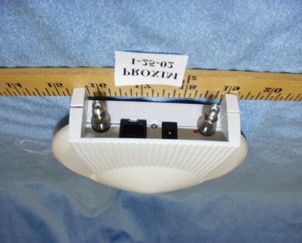
IMK-AP5C
Mar 14, 2002Harmony 802.11a Access Point
Equipment Class
NII - Unlicensed National Information Infrastructure TX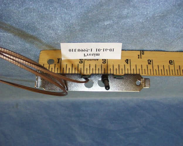
IMK-PCI5
Nov 15, 2001Harmony 8150 PCI Card
Equipment Class
NII - Unlicensed National Information Infrastructure TX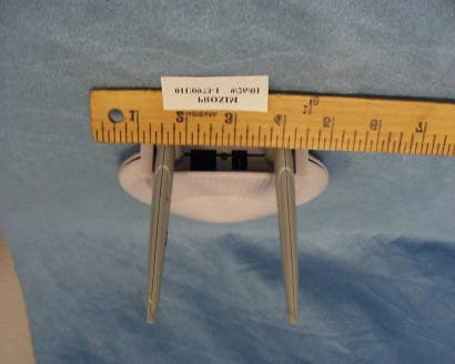
IMK-AP5
Nov 15, 2001Wireless LAN Access Point
Equipment Class
NII - Unlicensed National Information Infrastructure TX
IMK-HRFGW2
Sep 13, 2001Wireless LAN Base Station
Equipment Class
DSS - Part 15 Spread Spectrum Transmitter
IMK-HRFPC2
Jul 19, 2001Symphony Home RF PC Card Adapter
Equipment Class
DSS - Part 15 Spread Spectrum Transmitter