IMK-AP5Wireless LAN Access Point
Proxim Inc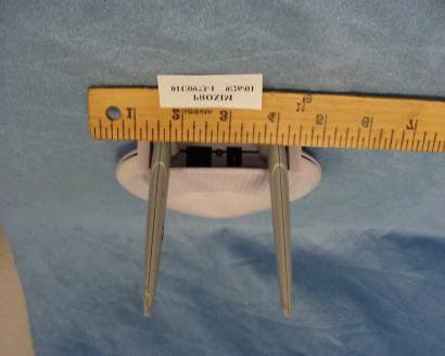
Click to zoom
Application Details
- Equipment Class
- NII - Unlicensed National Information Infrastructure TX
- Date of Grant
- Nov 15, 2001
- Application Purpose
- Original Equipment
- Date of Application
- Nov 15, 2001
- Equipment Note
- Wireless LAN Access Point
- Frequency Range
- 5250.00000000 - 5350.00000000
- Company
- Proxim Inc
- Country
- United States
Documents & Files
Document Text
Text extracted from the exhibit documents filed with the FCC. Open a document above to read the original.
Users Manual
Harmony 802.11a Access Point User's Guide Harmony AP.book Page i Wednesday, October 3, 2001 4:12 PM Copyright © 2001 Proxim, Inc., Sunnyvale, CA. All rights reserved. Covered by one or more of the following U.S. patents: 5,231,634; 5,875,179; 6,006,090. This user’s guide and the software described in it are copyrighted with all rights reserved. No part of this publication may be reproduced, transmitted, transcribed, stored in a retrieval system, or translated into any language in any form by any means without the written permission of Proxim, Incorporated. Trademarks Harmony, the Harmony logo, Proxim, and the Proxim logo are trademarks of Proxim, Inc. All other trademarks are the property of their respective owners. Limited Warranty, Disclaimer, Limitation Of Liability For a period of one (1) year from the date of purchase by the retail customer, Proxim warrants the Harmony 802.11a Access Point Model 8570 against defects in materials and workmanship. Proxim will not honor this warranty if there has been any attempt to tamper with or remove the product's external foil label. This warranty does not cover and Proxim will not be liable for any damage or failure caused by misuse, abuse, acts of God, accidents, or other causes beyond Proxim's control, or claim by any entity other than the original purchaser. If, after inspection, Proxim determines there is a defect, Proxim will repair or replace the Access Point at no cost to you. To return defective merchandise to Proxim please call Proxim Technical Support 1-408-731- 2640 to obtain a Return Merchandise Authorization (RMA) number. In no event shall Proxim, Incorporated be responsible or liable for any damages arising: • From the use of the product • From the loss of use, revenue or profit of the product • As a result of any event, circumstance, action, or abuse beyond the control of Proxim, Incorporated Whether such damages be direct, indirect, consequential, special or otherwise and whether such damages are incurred by the person to whom this warranty extends or a third party. Warranty Return Policy If you have a problem with the Harmony 802.11a Access Point Model 8570, please call Proxim Technical Support at 1-408-731-2640. Proxim Technical Support will assist with resolving any technical difficulties you may have with your Proxim product. After calling Proxim Technical Support, if your product is found to be defective, you may return the product to Proxim after obtaining an RMA (Return Merchandise Authorization) number. The product must be returned in its original packaging. The RMA number should be clearly marked on the outside of the box. Proxim cannot be held responsible for any product returned without an RMA number, and no product will be accepted without an RMA number. FCC WARNING This equipment has been tested and found to comply with the limits for a Class B digital device, pursuant to Part 15 of the FCC Rules. These limits are designed to provide reasonable protection against harmful interference in a residential installation. This equipment generates, uses, and can radiate radio frequency energy and, if not installed and used in accordance with the instructions, may cause harmful interference to radio communications. However, there is no guarantee that interference will not occur in a particular installation. If this equipment does cause harmful interference to radio or television reception, which can be determined by turning the equipment off and on, the user is encouraged to try to correct the interference by one or more of the following measures: • Reorient or relocate the receiving antenna. • Increase the separation between the equipment and the receiver. • Connect the equipment into an outlet on a circuit different from that which the receiver is con- nected. • Consult the dealer or an experienced radio/TV technician for help. Harmony 802.11a Access Point Model 8570 User’s Guide Part # 7360.0150 Rev. A AP.book Page ii Wednesday, October 3, 2001 4:12 PM i Table of Contents Chapter 1 - Introduction .......................................................................................1 The Harmony Family ......................................................................................... 2 Requirements ................................................................................................... 3 Package contents ............................................................................................. 3 Access Point Overview ..................................................................................... 4 Top Panel LEDs ........................................................................................... 4 Status LED ............................................................................................ 4 Wireless LED ......................................................................................... 5 Ethernet LED ......................................................................................... 5 Rear Panel .................................................................................................. 5 Ethernet Port ........................................................................................ 5 Ethernet Link/Activity LED .................................................................... 5 Power Port ............................................................................................ 5 Chapter 2 - Installation .........................................................................................7 Pre-installation Considerations ........................................................................ 7 Regulatory Warnings .................................................................................. 7 FCC Guidelines ...................................................................................... 7 Radio Frequency interference requirements ......................................... 7 Installation ...................................................…
Text truncated - open the document above for the full version.
Users Manual
Page 1 10/1/01 Harmony 8570 Access Point Technical Description Document # 610.00xx PRODUCT: The product is a WLAN adapter operating in the 5.15 – 5.35 GHz band with a maximum TX output power of 50mW. It is a small desktop box with associated wall plug mounted 12VDC power supply, dual external antennas and a 10/100baseT port for connection to standard wired LAN. The peak gain for each antenna is 6dBi. Refer to the manual for MPE statement. This device can either be stand alone connected to an RJ-45 LAN hub port, or be connected to the RJ-45 port of a computing device. USER CONNECTIONS: There is a single RJ-45 connector supplied for the single 10/100baseT port. The LED next to the RJ-45 changes colors to indicate the different connection speeds and blinks to indicate Ethernet activity. The 12VDC power is connected via a 2.5mm coaxial power connector. TEST CONNECTIONS: There are two 50 ohm RF ports on the PCA, one for each of the two antenna connections. Each antenna is terminated with a Radiall UMP2.0 snap-on plug. A slide-on version of the plug can be used during FCC certification for conducted measurements. ACCESSORIES: Proxim P/N 4000.0007 wall mounted unregulated power supply, 100-120V/50-60Hz input, 12V 1A nominal output. Proxim P/N 4000.0030 universal power supply, 100-240V/47-63Hz, 0.8A input, 12V, 1.5A nominal output. Proxim P/N 6001.0124 unshielded twisted pair RJ-45 cable assembly. INTERNAL CLOCK AND RF OSCILLATOR FREQUENCIES: Processor ASIC 33MHz Ethernet controller 25MHz RF synthesizer PLL frequencies of 40, 80, or 160MHz derived from a 32 MHz oscillator TX and RX frequencies 5180-5320MHz, 20MHz steps LO Leakage 4144-4256MHz Mixer Product 6216-6384MHz Baseband bandwidth 20MHz SIGNAL FLOW: The memory and Ethernet controller communicate with the processor IC. The MAC/baseband processor integrates the media access control (MAC), the baseband radio functions, A/D and D/A converters, transceiver control functions and a PCI/Cardbus interface. The Ethernet controller and processor ASIC each support their own on board clock oscillators at 25 and multiples of 33MHz to include 100MHz and 200MHz. In transmit, the synthesizer tunes to one of the TX frequencies listed above. Data is initiated at the Ethernet interface. The Ethernet controller processes serial data to the SDRAM which is then processed by the internal PCI controller within the processor IC to the MAC/baseband processor. Current outputs from the DAC of the MAC/baseband processor are low-pass filtered through the external reconstruction filter. The I and Q signals are converted to RF thru a dual-conversion architecture, from baseband to IF and from IF to RF signals. These signals are driven off-chip through a power amplifier, through the antenna switch, and to the antenna connector. Page 2 10/1/01 In receive, the synthesizer tunes to one of the RX frequencies listed above. The receive signal path is from the antenna connector, through the antenna switch, a band pass filter, an LNA, a receive balun, and to the integrated transceiver IC. Inside the transceiver IC, the RF mixer converts the output of the on-chip LNA to an intermediate frequency. The IF mixer converts this signal down to baseband I and Q signals. The I and Q signals are low-pass filtered by the external channel select filters, and amplified by a baseband PGA controlled by digital logic. The baseband signals continue through external anti-alias filters before being sent to the ADC of the MAC/baseband processor. Data at the PCI interface of the MAC/baseband processor is processed by the PCI controller within the processor IC to SDRAM which is then processed by the Ethernet controller to serial data to be sent to the Ethernet interface.
RF Exposure Info
REPORT NO.01U0973-1 FCC ID: IMK-AP5 DATE:09/25/2001 EUT: ACCESS POINT Page 46 of 66 COMPLIANCE CERTIFICATION SERVICES DOCUMENT NO: CCSUP4010B 561F MONTEREY ROAD, MORGAN HILL CA 95037 TEL:(408)463-0885 FAX:(408)463-0888 This report shall not be reproduced except in full, without the written approval of CCS. RF EXPOSUER (F) (f) U-NII devices are subject to the radio frequency radiation exposure requirements specified in § 1.1307(b), § 2.1091 and § 2.1093 of this chapter, as appropriate. All equipment shall be considered to operate in a "general population/uncontrolled" environment. Applications for equipment authorization of devices operating under this section must contain a statement confirming compliance with these requirements for both fundamental emissions and unwanted emissions. Technical information showing the basis for this statement must be submitted to the Commission upon request. § 1.1310 Radio Frequency Radiation Exposure TABLE 1—LIMITS FOR MAXIMUM PERMISSIBLE EXPOSURE (MPE) Frequency range | Electric field Magnetic field Power density Averaging time (MHz) Strength Strength (mW/cm 2 ) (minutes) (V/m) (A/m) (B) Limits for General Population/Uncontrolled Exposure 0.3–1.34 ..................... ..... 614 1.63 *(100) 30 1.34–30 ..........................824/f 2.19/f *(180/f 2 ) 30 30–300 ............................ 27.5 0.073 0.2 30 300–1500 ....................................................... ..............................f/1500 30 1500–100,000 ................................................ .............................. .. 1.0 30 Test result: TABLE 1 (B) LIMITS FOR GENERAL POPULATION/UNCONTROLLED EXPOSURE F(MHz) (POWER DENSITY (mW/cm²) 1500 - 100,000 1 Transmitter Output power is 0.049 Watts and will be used with a 1 dBi (3.98 numerically) antenna Computation method: P = E ² / 3770 √E² =√1 mW/cm² * 3770 E = 61.4 V/m E = √ 30* P * G D REPORT NO.01U0973-1 FCC ID: IMK-AP5 DATE:09/25/2001 EUT: ACCESS POINT Page 47 of 66 COMPLIANCE CERTIFICATION SERVICES DOCUMENT NO: CCSUP4010B 561F MONTEREY ROAD, MORGAN HILL CA 95037 TEL:(408)463-0885 FAX:(408)463-0888 This report shall not be reproduced except in full, without the written approval of CCS. D = √ 30 * 0.049 * 3.98 61.4 V/m D = 3.93 cm 3.93 / 2.54 = 1.55 inch MPE DISTANCE REQUIREMENT IS 1.55 INCH. A WARNING STATEMENT WITH A MPE DISTANCE REQUIREMENT OF 20CM IS PLACED IN THE MANUAL.
Test Report
ELECTROMAGNETIC EMISSIONS COMPLIANCE REPORT UNLICENSED NATIONAL INFORMATION INFRASTRUCTURE DEVICES CERTIFICATION TO FCC PART 15 SUBPART E REQUIREMENT TEST REPORT For ACCESS POINT UNLICENSED NATIONAL INFORMATION INFRASTRUCTURE DEVICES TRANSCEIVER FCC ID: IMK-AP5 MODEL NO: PROXIM HARMONY 8570 AP REPORT NO: 01U0973-1 SEPTEMBER 26, 2001 Prepared for PROXIM 510 DEGUIGNE DRIVE SUNNYVALE, CA. 94086 USA Prepared by COMPLIANCE CERTIFICATION SERVICES 561F MONTEREY ROAD, MORGAN HILL, CA. 95037, U.S.A. TEL: (408) 463-0885 FAX: (408) 463-0888 TABLE OF CONTENTS PAGE 1. VERIFICATION OF COMPLIANCE............................................................................................................3 2. DESCRIPTION OF EQUIPMENT UNDER TEST (EUT)...........................................................................4 3. TEST LOCATION............................................................................................................................................5 4. LABORATORY ACCREDITATIONS AND LISTINGS.............................................................................6 5. SUPPORT/ TEST EQUIPMENT....................................................................................................................7 Support Equipment..............................................................................................................................................7 Test Equipment....................................................................................................................................................7 I/O Cable Configuration.....................................................................................................................................8 Test Configuration Diagram...............................................................................................................................8 6. TEST PROCEDURES AND TEST RESULTS..............................................................................................9 MODIFICATIONS..................................................................................................................................................9 RADIATED EMISSIONS TEST REQUIREMENT: 15.209...............................................................................................10 AC LINE CONDUCTED EMISSIONS TEST REQUIREMENT: 15.207...........................................................................12 RESTRICTED BAND TEST REQUIMENT: 15:205...................................................................................................16 BANDEDGE..........................................................................................................................................................21 PEAK POWER FOR UNII TEST REQUIREMENT: 15.407(A)1-2...........................................................................26 PEAK POWER SPECTRAL DENSITY TEST REQUIREMENT: 15.407(A)5......................................................................31 PEAK EXCURSION TO AVERAGE RATIO: 15.407(A)6...............................................................................................33 OUT OF BAND EMISSION 15.407 (B) 1-2.................................................................................................................35 15.407 SUPPLEMENT TEST...............................................................................................................................43 15.407 SUPPLEMENT TEST......................................................................................................................................44 INTEGRAL ANTENNA (D).........................................................................................................................................45 RF EXPOSUER (F)..................................................................................................................................................46 7. TEST SETUP PHOTO.........................................................................................................................................48 RADIATED EMISSSION SETUP PHOTOS....................................................................................................................48 CONDUCTED EMISSION SETUP PHOTOS....................................................................................................................49 HI FREQUENCY SETUP PHOTOS...............................................................................................................................50 ANTENNA PORT MEASUREMENT PHOTOS...............................................................................................................51 Attachments • Eut Photographs • Proposed FCC ID Label • Agent Authorization • Request for Confidentiality • Technical Description • User’s Manual • Antenna Requirements • Confidential Package REPORT NO.01U0973-1 FCC ID: IMK-AP5 DATE:09/25/2001 EUT: ACCESS POINT Page 3 of 66 COMPLIANCE CERTIFICATION SERVICES DOCUMENT NO: CCSUP4010B 561F MONTEREY ROAD, MORGAN HILL CA 95037 TEL:(408)463-0885 FAX:(408)463-0888 This report shall not be reproduced except in full, without the written approval of CCS. 1. VERIFICATION OF COMPLIANCE COMPANY NAME : PROXIM 510 DEGUIGNE DRIVE SUNNYVALE, CA 94086 INFO CONTACT : KEITH GLOVER TELEPHONE NO : 408-731-2711/408-731- 2706 TECHNICAL CONTACT: JEFFREY LIEW TELEPHONE NO : 408-731-2734 EUT DESCRIPTION : 802.11a ACCESS POINT MODEL NAME : PROXIM HARMONY MODEL 8570 ACCESS POINT DATE TESTED : SEPTEMBER 26, 2001 LIMIT APPLY TO: FCC PART 15 SECTION 15.407 TECHNICAL LIMITS TEST RESULT Peak Transmit Power @ 5.15-5.25GHz < 17dBm Complies Peak Transmit Power @ 5.25-5..35GHz < 24dBm Complies Power Density @ 5.15-5.25GHz < 4dBm / 1M Complies Power Density @ 5.25-5..35GHz < 11dBm / 1M Complies Peak Excursion to Average Ratio < 13dB Complies Out of Band EIRP < -27 dBm/MHz Complies LIMIT APPLY TO: FCC PART 15 SECTION 15.205 Restricted Band of Operation Complies LIMIT APPLY TO: FC…
Text truncated - open the document above for the full version.
Test Setup Photos
REPORT NO.01U0973-1 FCC ID: IMK-AP5 DATE:09/25/2001 EUT: ACCESS POINT Page 48 of 66 COMPLIANCE CERTIFICATION SERVICES DOCUMENT NO: CCSUP4010B 561F MONTEREY ROAD, MORGAN HILL CA 95037 TEL:(408)463-0885 FAX:(408)463-0888 This report shall not be reproduced except in full, without the written approval of CCS. 7. TEST SETUP PHOTO RADIATED EMISSSION SETUP PHOTOS REPORT NO.01U0973-1 FCC ID: IMK-AP5 DATE:09/25/2001 EUT: ACCESS POINT Page 49 of 66 COMPLIANCE CERTIFICATION SERVICES DOCUMENT NO: CCSUP4010B 561F MONTEREY ROAD, MORGAN HILL CA 95037 TEL:(408)463-0885 FAX:(408)463-0888 This report shall not be reproduced except in full, without the written approval of CCS. CONDUCTED EMISSION SETUP PHOTOS REPORT NO.01U0973-1 FCC ID: IMK-AP5 DATE:09/25/2001 EUT: ACCESS POINT Page 50 of 66 COMPLIANCE CERTIFICATION SERVICES DOCUMENT NO: CCSUP4010B 561F MONTEREY ROAD, MORGAN HILL CA 95037 TEL:(408)463-0885 FAX:(408)463-0888 This report shall not be reproduced except in full, without the written approval of CCS. HI FREQUENCY SETUP PHOTOS REPORT NO.01U0973-1 FCC ID: IMK-AP5 DATE:09/25/2001 EUT: ACCESS POINT Page 51 of 66 COMPLIANCE CERTIFICATION SERVICES DOCUMENT NO: CCSUP4010B 561F MONTEREY ROAD, MORGAN HILL CA 95037 TEL:(408)463-0885 FAX:(408)463-0888 This report shall not be reproduced except in full, without the written approval of CCS. ANTENNA PORT MEASUREMENT PHOTOS
Contact Information
Applicant
Keith Glover(Vice President)
Test Firm
Compliance Certification Services IncSteve Cheng
Technical Specifications
| # | Rule Parts | Frequency Range | Power Output |
|---|---|---|---|
| 2 | 15E | 5.25 GHz - 5.35 GHz | 49.00 mW |
Other Applications from Proxim Inc
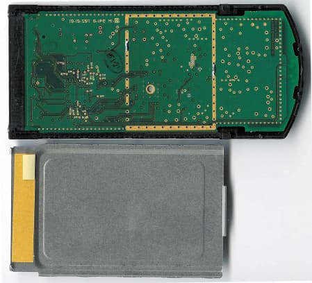
IMK-8455
Dec 05, 2002802.11a Cardbus
Equipment Class
NII - Unlicensed National Information Infrastructure TX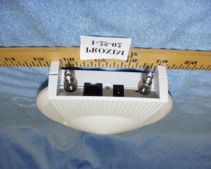
IMK-AP5C
Mar 14, 2002Harmony 802.11a Access Point
Equipment Class
NII - Unlicensed National Information Infrastructure TX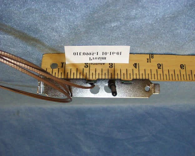
IMK-PCI5
Nov 15, 2001Harmony 8150 PCI Card
Equipment Class
NII - Unlicensed National Information Infrastructure TX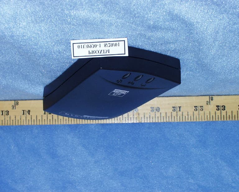
IMK-HRFGW2
Sep 13, 2001Wireless LAN Base Station
Equipment Class
DSS - Part 15 Spread Spectrum Transmitter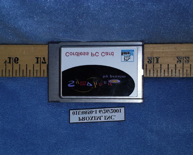
IMK-HRFPC2
Jul 19, 2001Symphony Home RF PC Card Adapter
Equipment Class
DSS - Part 15 Spread Spectrum Transmitter