IMK-ILCPCIWireless LAN Adapter
Proxim Inc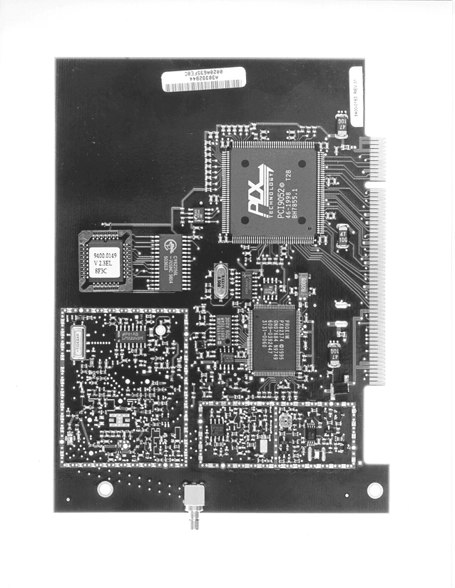
Click to zoom
Application Details
- Equipment Class
- DSS - Part 15 Spread Spectrum Transmitter
- Date of Grant
- May 02, 1999
- Application Purpose
- Original Equipment
- Date of Application
- Mar 17, 1999
- Equipment Note
- Wireless LAN Adapter
- Frequency Range
- 2402.00000000 - 2480.00000000
- Company
- Proxim Inc
- Country
- United States
Documents & Files
Document Text
Text extracted from the exhibit documents filed with the FCC. Open a document above to read the original.
Test Report
Elliott Laboratories, Inc. -- EMC DepartmentTest Report Report Date: March 11, 1999 File: R30698Page 2 of 17 pages TABLE OF CONTENTS COVER PAGE....................................................................................... 1 TABLE OF CONTENTS............................................................................ 2 TABLE OF CONTENTS Continued.............................................................. 3 SCOPE................................................................................................ 4 OBJECTIVE.......................................................................................... 4 STATEMENT OF COMPLIANCE................................................................ 4 EMISSION TEST RESULTS...................................................................... 5 LIMITS OF CONDUCTED INTERFERENCE VOLTAGE........................... 5 LIMITS OF ANTENNA CONDUCTED POWER...................................... 5 LIMITS OF RADIATED INTERFERENCE FIELD STRENGTH................... 5 MEASUREMENT UNCERTAINTIES.................................................. 7 COMPLIANCE EXPLANATION........................................................ 7 EQUIPMENT UNDER TEST (EUT) DETAILS................................................. 8 GENERAL................................................................................... 8 INPUT POWER............................................................................. 8 PRINTED WIRING BOARDS............................................................ 8 SUBASSEMBLIES......................................................................... 8 ENCLOSURE............................................................................... 9 ANTENNA.................................................................................. 9 EMI SUPPRESSION DEVICES.......................................................... 9 MODIFICATIONS.......................................................................... 9 SUPPORT EQUIPMENT.................................................................. 9 EXTERNAL I/O CABLING.............................................................. 10 TEST SOFTWARE........................................................................ 10 TEST SITE........................................................................................... 11 GENERAL INFORMATION............................................................. 11 CONDUCTED EMISSIONS CONSIDERATIONS................................... 11 RADIATED EMISSIONS CONSIDERATIONS...................................... 11 MEASUREMENT INSTRUMENTATION..................................................... 12 INSTRUMENT CONTROL COMPUTER............................................. 12 LINE IMPEDANCE STABILIZATION NETWORK (LISN)....................... 12 POWER METER........................................................................... 13 FILTERS/ATTENUATORS.............................................................. 13 ANTENNAS................................................................................ 13 ANTENNA MAST AND EQUIPMENT TURNTABLE.............................. 13 INSTRUMENT CALIBRATION........................................................ 13 TEST PROCEDURES.............................................................................. 14 EUT AND CABLE PLACEMENT...................................................... 14 CONDUCTED EMISSIONS............................................................. 14 RADIATED EMISSIONS................................................................. 14 CONDUCTED EMISSIONS FROM ANTENNA PORT............................. 14 SPECIFICATION LIMITS AND SAMPLE CALCULATIONS.............................. 15 CONDUCTED EMISSIONS SPECIFICATION LIMITS, SECTION 15.207.... 15 RADIATED EMISSIONS SPECIFICATION LIMITS, SECTION 15.209........ 15 SAMPLE CALCULATIONS - CONDUCTED EMISSIONS........................ 16 SAMPLE CALCULATIONS - RADIATED EMISSIONS........................... 17 Elliott Laboratories, Inc. -- EMC DepartmentTest Report Report Date: March 11, 1999 File: R30698Page 3 of 17 pages TABLE OF CONTENTS Continued EXHIBIT 1:Test Equipment Calibration Data................................................. 1 EXHIBIT 2:Test Data Log Sheets............................................................... 2 EXHIBIT 3:Radiated Emissions Test Configuration Photographs.......................... 3 EXHIBIT 4:Conducted Emissions Test Configuration Photographs....................... 4 EXHIBIT 5:Proposed FCC ID Label & Label Location...................................... 5 EXHIBIT 6: Detailed Photographs of Proxim Model 4110-05 Construction............... 6 EXHIBIT 7:Operator's Manual for Proxim Model 4110-05................................. 7 EXHIBIT 8:Block Diagram of Proxim Model 4110-05...................................... 8 EXHIBIT 9:Schematic Diagrams for Proxim Model 4110-05............................... 9 EXHIBIT 10: Theory of Operation for Proxim Model 4110-05.............................. 10 Elliott Laboratories, Inc. -- EMC DepartmentTest Report Report Date: March 11, 1999 File: R30698Page 4 of 17 pages SCOPE An electromagnetic emissions test has been performed on the Proxim Spread Spectrum Wireless LAN Adapter model 4110-05 pursuant to Subpart C of Part 15 of FCC Rules for intentional radiators. Conducted and radiated emissions data has been collected, reduced, and analyzed within this report in accordance with measurement guidelines set forth in ANSI C63.4-1992 as outlined in Elliott Laboratories test procedures. The intentional radiator above has been tested in a simulated typical installation to demonstrate compliance with the relevant FCC performance and procedural standards. Final system data was gathered in a mode that tended to maximize emissions by varying orientation of EUT, orientation of power and I/O cabling, antenna search height, and antenna polarization. Every practical effort was made to perform an impartial test using approp…
Text truncated - open the document above for the full version.
Test Report
EMC Test Log Client:Proxim, Inc.Date:2/24/99Test Engr: Rudy Suy Product:4110-05File:T30505Proj. Eng:Mark Briggs Objective:Final QualificationSite:SVOATS#2Contact:Pete Garcia Spec:FCC Part 15Page: 1 of 4Approved: Revision1.0 Ambient Conditions Temperature:8 . 9 °C Humidity:7 3 % Test Objective The objective of this test session is to perform final qualification testing the EUT defined below relative to the specifications defined above. Test Summary Run #1 - Channel Separation and Utilization {15.247(a) (1)} see test data log. Channel separation was measured and calculated to be 995.3KHz (79 channels in 78.6 MHz) The 20dB bandwidth was measured to be: Low Channel925 KHz Central Channel 958 KHz High Chennel942 KHz Run #1 - Output Power {15.247(b)} see test data log. Low Channel19.7 dBm Central Channel19.8 dBm High Chennel19.8 dBm Maximum output power was 19.8 dBm (0.096 Watts), meeting maximum permitted of 1 Watt. Run #3a - Maximized Radiated Emissions, 1-25 GHz , Channel #1 (Low Channel) PASSResults: FCC B-3.4 dB [email protected] MHzVertical Run #3b - Maximized Radiated Emissions, 1-25 GHz , Channel #39 (Center Channel) PASSResults: FCC B-7.3 dB [email protected] MHzVertical Run #3c - Maximized Radiated Emissions, 1-25 GHz , Channel #79 (High Channel) PASSResults: FCC B-7.2 dB [email protected] MHzVertical EMC Test Log Client:Proxim, Inc.Date:2/24/99Test Engr: Rudy Suy Product:4110-05File:T30505Proj. Eng:Mark Briggs Objective:Final QualificationSite:SVOATS#2Contact:Pete Garcia Spec:FCC Part 15Page: 2 of 4Approved: Revision1.0 Equipment Under Test (EUT) General Description The EUT Symphony PCI Card is a wireless LAN adapter with a low power frequency hopping spread spectrum (FHSS) radio system operating in the 2400-2483.5 MHz band. The Symphony PCI Card uses 79 channels, each 1 MHz wide. The system hops over one of 15 pseudo random sequences. On the average, each channel is used equally. Please refer to "RANGELAN2 Frequency Hopping Theory of Operation" attached to this submission. (Note that confidentiality has been requested for the Theory of Operation exhibit) Normally, the EUT would be placed on a table top during operation. The EUT was, therefore, placed in this position during emissions testing to simulate the end user environment. The electrical rating of the EUT is 120/240 V, 50/60 Hz. Equipment Under Test (EUT) Manufacturer/Model/DescriptionSerial NumberFCC ID Number Proxim, Symphony PCI, Spread Spectrum Wireless LAN Adapter A30392835IMK-ILCPCI Power Supply and Line Filters DescriptionManufacturerModel None-- The EUT power was derived from the host computer power supply. Printed Wiring Boards in EUT Manufacturer/DescriptionAssembly #Rev.Serial NumberCrystals (MHz) Proxim PCI Card8400-016301A303928358, 32 Subassemblies in EUT Manufacturer/DescriptionAssembly NumberRev.Serial Number None--- EUT Enclosure(s) The EUT does not have an enclosure as it is designed to be installed within the enclosure of a host computer. EMC Test Log Client:Proxim, Inc.Date:2/24/99Test Engr: Rudy Suy Product:4110-05File:T30505Proj. Eng:Mark Briggs Objective:Final QualificationSite:SVOATS#2Contact:Pete Garcia Spec:FCC Part 15Page: 3 of 4Approved: Revision1.0 EMI Suppression Devices (filters, gaskets, etc.) DescriptionManufacturerPart Number None-- Modifications The following modifications were made to the EUT in order to comply with the requirements: None Local Support Equipment Manufacturer/Model/DescriptionSerial NumberFCC ID Number Dell, Dimension P133v, PC8Q28FE2JHANNIBAD Dell, D1728D-LS, Monitor04036A8M60A3LCMG737 Dell, SK-1000REW, Keyboard12741-71H-9024GYUR26SK Dell, M-S34, MouseLZA70606597DZL210472 HP, 2225C+, Printer3028S76892DS16XU2225 Proxim, Antenna 1900.0051-- Remote Support Equipment Manufacturer/Model/DescriptionSerial NumberFCC ID Number None-- Interface Cabling Cable DescriptionLength (m)From Unit/PortTo Unit/Port Shielded Parallel Cable2.5PC/ ParralelPrinter Shielded Keyboard Cable2.0PC/ Keyboard PortKeyboard Shielded Mouse Cable2.0PC/ Mouse PortMouse Shielded Video Cable1.5PC/ Video PortMonitor Shielded Antenna Cable1.5PC/EUT RF PortAntenna Test Software The host PC contained test software running during testing which continuously exercised the EUT. EMC Test Log Client:Proxim, Inc.Date:2/24/99Test Engr: Rudy Suy Product:4110-05File:T30505Proj. Eng:Mark Briggs Objective:Final QualificationSite:SVOATS#2Contact:Pete Garcia Spec:FCC Part 15Page: 4 of 4Approved: Revision1.0 General Test Conditions During radiated testing, the host PC was connected to 120V, 60Hz power input. The host PC and all local support equipment were located on the turntable for radiated testing and conducted testing. Equipment Under Test Placed on Non Conductive Table Inside Non Conductive Turntable Building 2.5 meter X 2.5 meter Vertical Ground Plane Electrically Connected to OATS Ground Plane Along Bottom Edge Vertical Ground Plane Raised on Outside of Building During Conducted Testing Only Test Data Tables See attached data Emissions Test Data Client: Proxim, Inc.Date:2/24/99Test Engr: Rudy Suy Product: 4110-05File:T30505Proj. Engr: Mark H & B ObjectiveFinal QualificationSite:SVOATS #2Contact:Jeff Spec:FCC Part 15Distance:3 mApproved: Ambient Conditions Temperature:8 °C Humidity:87 % Elliott Lab equipment: Analyzer #284, Horn #487, pre-amp #870 & High pass filter #247 Run #1: Channel Separation and Utilization {15.247(a) (1)} Channel separation was measured and calculated to be 995.3KHz (79 channels in 78.6 MHz) The 20dB bandwidth was measured to be: Low Channel 925 KHz Center Channel 958 KHz High Channel 942 KHz The 20dB bandwidth was measured using a 30kHz resolution bandwidth rather than 100 kHz bandwidth. Proxim have a waiver from the FCC allowing this deviation. The channel separation exceeds the 20dB bandwidth and the 20dB bandwidth is less than 1MHz, therefore the unit complies. Channel occupancy was 395 mSeconds with the unit transmitting a packet size of 1500 with a 0mS delay (worst case). Each channel was used twice in a 60…
Text truncated - open the document above for the full version.
Contact Information
Applicant
Keith Glover(Vice President)
Technical Contact
Elliott Laboratories Inc.Mark Briggs
[email protected]408 245 7800
684 W. Maude Ave. · Sunnyvale, California · United States
Non-Technical Contact
Elliott Laboratories, Inc.Mark Briggs
[email protected]408-245-7800
Technical Specifications
| # | Rule Parts | Frequency Range | Power Output | Tolerance |
|---|---|---|---|---|
| 1 | 15C | 2.40 GHz - 2.48 GHz | 96.00 mW | 100.0000000000 ppm |
Other Applications from Proxim Inc
IMK-8455
Dec 05, 2002802.11a Cardbus
Equipment Class
NII - Unlicensed National Information Infrastructure TX
IMK-AP5C
Mar 14, 2002Harmony 802.11a Access Point
Equipment Class
NII - Unlicensed National Information Infrastructure TX
IMK-PCI5
Nov 15, 2001Harmony 8150 PCI Card
Equipment Class
NII - Unlicensed National Information Infrastructure TX
IMK-AP5
Nov 15, 2001Wireless LAN Access Point
Equipment Class
NII - Unlicensed National Information Infrastructure TX
IMK-HRFGW2
Sep 13, 2001Wireless LAN Base Station
Equipment Class
DSS - Part 15 Spread Spectrum Transmitter