IMK-STMP-10-1
Proxim Inc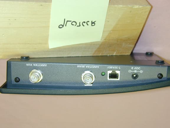
Click to zoom
Application Details
- Equipment Class
- DSS - Part 15 Spread Spectrum Transmitter
- Date of Grant
- Aug 06, 2000
- Application Purpose
- Original Equipment
- Date of Application
- May 31, 2000
- Frequency Range
- 2417.00000000 - 2457.00000000
- Company
- Proxim Inc
- Country
- United States
Documents & Files
Document Text
Text extracted from the exhibit documents filed with the FCC. Open a document above to read the original.
Users Manual
STRATUM TM MP Point-to-Multipoint Wireless Ethernet Bridge User’s Guide Draft A (5/2000) i Copyright © 2000 Proxim, Inc., Sunnyvale, CA. All rights reserved. This manual and the software described in it are copyrighted with all rights reserved. No part of this publication may be reproduced, transmitted, transcribed, stored in a retrieval system or translated into any language in any form by any means without the written permission of Proxim, Incorporated. Trademarks Stratum TM , Stratum MP, and Proxim are trademarks of Proxim, Inc. All other trademarks are the property of their respective owners. Limited Warranty, Disclaimer, Limitation Of Liability For a period of two (2) years from the date of purchase by the retail customer, Proxim warrants the Stratum MP against defects in materials and workmanship. Proxim will not honor this warranty if there has been any attempt to tamper with or remove the product’s external foil label. This warranty does not cover and Proxim will not be liable for any damage or failure caused by misuse, abuse, acts of God, accidents, or other causes beyond Proxim's control, or claim by other than the original purchaser. If, after inspection, Proxim determines there is a defect, Proxim will repair or replace the Stratum MP at no cost to you. To return defective merchandise to Proxim please call Proxim Technical Support 1-408-731- 2640 to obtain a Return Merchandise Authorization (RMA) Number. In no event shall Proxim, Incorporated be responsible or liable for any damages arising: q From the use of the product; q From the loss of use, revenue or profit of the product; or q As a result of any event, circumstance, action, or abuse beyond the control of Proxim, Incorporated; Whether such damages be direct, indirect, consequential, special, or otherwise and whether such damages are incurred by the person to whom this warranty extends or to a third party. Warranty Return Policy If you have a problem with the Stratum MP, please call Proxim Technical Support at 1-408-731-2640. Proxim Technical Support will assist with resolving any technical difficulties you may have with your Proxim product. After calling Proxim Technical Support, if your product is found to be defective, you may return the product to Proxim after obtaining an RMA (Return Materials Authorization) number. The product must be returned in its original packaging. The RMA number should be clearly marked on the outside of the box. Proxim cannot be held responsible for any product returned without an RMA number, and no product will be accepted without an RMA number. Part # 7630.xxxx Rev. A ii FCC WARNING This device complies with Part 15 of the FCC Rules. Operation is subject to the following two conditions: (1) This device may not cause harmful interference, and (2) this device must accept any interference received, including interference that may cause undesired operation. This equipment has been tested and found to comply with the limits for a Class B digital device, pursuant to Part 15 of the FCC Rules. These limits are designed to provide reasonable protection against harmful interference in a residential installation. This equipment generates, uses, and can radiate radio frequency energy and, if not installed and used in accordance with the instructions, may cause harmful interference to radio communications. However, there is no guarantee that interference will not occur in a particular installation. If this equipment does cause harmful interference to radio or television reception, which can be determined by turning the equipment off and on, the user is encouraged to try to correct the interference by one or more of the following measures: qReorient or relocate the receiving antenna. qIncrease the separation between the equipment and the receiver. qConnect the equipment into an outlet on a circuit different from that which the receiver is connected. qConsult the dealer or an experienced radio/TV technician for help. Modifications to this product not expressly approved by Proxim, Inc., could void the FCC approval and the user’s right operate the product. This equipment complies with FCC Regulations 15.247. The Stratum is intended for point-to-multipoint or point-to-point operations over an unobstructed line-of-sight path. iii EUROPEAN TELECOMMUNICATIONS STANDARDS INSTITUTE Statement of Compliance Information to User This equipment has been tested and found to comply with the European Telecommuni- cation Standard ETS 300.328. This standard covers Wideband Data Transmission Systems referred to in the CEPT recommendation T/R 10.01. This type of accepted equipment is designed to provide reasonable protection against harmful interference when the equipment is operated in a commercial environment. This equipment generates, uses and can radiate radio frequency energy and, if not installed and used in accordance with the instruction manual, may cause harmful interference to radio communications. SAFETY WARNING Before aiming the antenna or working near the antenna, read this entire manual and follow the instructions carefully. Be sure to provide adequate grounding and lightning protection. Do not install the antenna near overhead electrical wires. Warning! It is the responsibility of the user to ensure that the unit is properly installed in compliance with the FCC’s guidelines for maximum permissible radio frequency expo- sure outlined in CFR 47 Section 1.1307(b)(1), preventing excess exposure to all persons. The installed unit should be positioned to guarantee no direct continuous exposure to people within 20 cm (8 inches) of the antenna. Proper operation of this radio according to the instructions found in this manual will result in the user exposure to be substantially below the FCC recommended limits. Microwave radiation can cause tissue heating, potentially affecting the eyes, and causing permanent damage to vision. iv v Contents [WORK IN PROGRESS] 1. Introduction ............................................…
Text truncated - open the document above for the full version.
Attestation Statements
Federal Communications Commission 7435 Oakland Mills Road Columbia, MD 21046 USA Authority to Act as Agent to the Federal Communications Commission On our behalf, I appoint KTL Dallas, Inc. to act as agent in the preparation of this application for equipment authorization to the Federal Communications Commission. I certify that submitted Exhibits properly describe the device or system for which equipment authorization is sought. I also certify that each unit manufactured, imported or marketed, as defined in the Commission's regulations will have affixed to it a label identical to that submitted for approval with this application. APPLICANT ANTI-DRUG ABUSE CERTIFICATION: In signing this letter, Applicant certifies that, in the case of an individual applicant, he or she is not subject to a denial of federal benefits, that includes FCC benefits, pursuant to Section 5301 of the Anti-Drug Abuse Act of 1988, 21 U.S.C. 853(a), or, in the case of a non-individual applicant (e.g. corporation, partnership or other unincorporated association), no party to the application is subject to a denial of federal benefits, that includes FCC benefits, pursuant to that section. For the definition of a "party" for these purposes, see 47 CFR 1.2002(b). Dated this 9th Day of May, 2000 Agency agreement expiration date: September, 2000 By: John Cafarella Title: Director Telephone: 781-224-4004 Applicant: Proxim Inc.
Attestation Statements
REQUEST FOR CONFIDENTIALITY Proxim Inc. requests confidentiality with regard to the following documents in the filing for equipment approval identified by FCC ID. No. IMK-STMP-10-1 (1) All Schematic diagrams (2) All Block Diagrams (3) Technical Description It is the opinion of Proxim Inc. disclosure of this information would result in significant loss of revenue. This information should be kept confidential for 2 years. By: John Cafarella - Director Date: 5/9/00 Proxim Inc. 510 DeGuigne Dr. Sunnyvale, CA 94086
Cover Letter(s)
June 1, 2000 Federal Communications Commission Equipment Authorization Branch 7435 Oakland Mills Road Columbia, MD 21046 USA Reference: EA97764Proxim Inc. FCC ID: IMK-STMP-10-1 To Whom It May Concern: The Contact Information at Proxim Inc. is as follows: Contact Name: Ken Bennett Telephone #:(781)–224-4011 Fax #:(781)-246-0157 Email:[email protected] Please feel free to contact me with any questions you may have. Rega rds, Susan A. Griffith KT L Dallas, Inc. 802 N. Kealy Street Lewisville, Texas 75057-3136 Tel: (972)-436-9600 ext. 284 Fax: (972)-436-2667 email: [email protected]
External Photos
FCC Label Location
ID Label/Location Info
IMK-STMP-10-1
Operational Description
Measurement of Processing Gain of the Stratum MP May 1, 2000 I. A GENERAL DEFINITION OF THE PROCESSING GAIN The maximum available processing gain for a direct-sequence spread-spectrum system depends on the transmitted waveform, while the actual processing gain is measured at the receiver. The implementation loss (L sys ) is generally the difference between these. To determine the maximum available (theoretical) processing gain, usually the number of chips N c in the symbol waveform is considered as the nominal value, and certainly as the maximum value. But the generation of a complex waveform requires a more detailed calculation of the maximum available processing gain. The issue of independent degrees of freedom is the fundamental effect. The best method to calculate this is to assume an ideal receiver mathematically and match filter the received waveform. This maximum theoretical system processing gain represents the theoretical rejection of a center-band interfering signal, averaged over all chip-code patterns. The practical processing gain of the system must also take into account the SNR required for adequately low demodulation errors and the system implementation losses. The practical processing gain Gp is defined by 1 Gp = (S/N) req + Mj + Lsys (1) (all in dB) where !" (S/N) req is the minimum signal-to-noise ratio after de-spreading at which the given modulation can provide adequate error performance, !" Mj is the maximum ratio of interference power to the signal power, measured at the system input, for which the system can provide the adequate error performance, !" Lsys is the system implementation losses in SNR due to practical implementation limitations. II. CONSIDERATION OF ACTUAL PROCESSING GAIN First, the values used for S/N and Lsys will be discussed, then the measured values of Mj will be presented. A. REQUIRED SNR The data modulation employed is a form of bi-orthogonal signalling in which one of 16 waveforms plus differential phase is transmitted, conveying five bits of information during each 16-chip data symbol. Each digital waveform symbol goes through a waveform pulse shaping circuit that produces a continuous phase modulation (CPM) of the carrier, that results in a nearly-square spectral shape with low spectral side-bands. The theoretical coherent S/N performance in terms of probability of symbol error (Pse) can be computed using the similar calculations as 1 Dixon, R, Spread Spectrum Systems, Chapter 1 (New York: Wiley, 1994) shown for simple bi-orthogonal signaling in the graph on page 259 in Wozencraft and Jacobs 1 and assuming an ideal matched filter receiver . In fact, the manufacturer has performed simulation, numerical computation and experimentation (using unfiltered, perfectly timed received waveforms) to verify this performance. The theoretical processing gain of the chip waveform including the pulse shaping is 10.3 dB when using an ideal matched filter receiver. Adequate system performance is achieved when the radios have degraded to 90% of their maximum throughput. This level of throughput results in a Pse of 4*10 -5 (recall that each symbol is 5 data bits), resulting in an operating point output SNR = 14.8 dB. B. ANTICIPATED SYSTEM LOSS Lsys is the system implementation losses in SNR due to practical implementation limitations. System loss is due to a multitude of effects which include various filters, signal quantization, computation errors, timing misalignment, etc. The very tight filtering required to conform to FCC part 15 regulations, causes mismatch between the transmitted waveform and the much-less-filtered reference waveforms in the correlator bank. (The 2400-to-2483.5-MHz band resides between two protected bands which constrain the absolute levels of signal power which may be produced, unlike the relative-power-level constraint of the part 15.247 alone). This causes a loss of approximately 1.3 dB. This was measured by removing the filters on experimental boards. Signal quantization as well as round-off and truncation within the digital correlation subsystem result in approximately 0.45 dB departure from ideal. Timing error in the placement of the correlation processor relative to the received signal results in an average loss of 0.25 dB. The total implementation loss is consequently 2.0 dB. 1 Wozencraft and Jacobs, "Principles of Communications". III. MEASUREMENT PROCEDURE OF THE PROCESSING GAIN The practical processing gain may be measured using the CW jamming margin method. Figure 1 shows the test configuration . The actual test site is shown in Appendix-A. Figure 1 The “HP Internet advisor”, a data generator, is the source of continuous Ethernet frames. The rate of frame sourcing and all frame parameters can be set. The output of the “HP Internet Advisor” is fed to the Ethernet port on the Stratum MP (Transmit). A “Compaq Contura” PC is used on a local RS-232 control port on the Stratum MP for monitoring of the transmitter. An “HP8648C” signal generator is used as a jammer (causes CW interference). The desired signal and CW jamming signal are combined and then the sum is split for observation of power and for feeding to the Stratum MP (Receive). The Jammer-to-Signal (J/S) ratio is measured using HP 436A power meter. The power meter readout of the desired signal must be compensated using the transmit stream duty factor of the desired signal frames. The detailed compensation procedure is described in Appendix-B. The spectrum analyzer is exchanged with the power meter only to verify that operation is normal and all spectra are as anticipated. The output signal of the receiving radio is a stream of Ethernet frames that is fed through the “HPJ2610A Stack Hub” 10BaseT port to the “DELL Latitude Xpi” Ethernet card. The “DELL Latitude Xpi” is running “Lanalyzer”, a LAN monitoring software package supplied by Novell, used for measuring the rate of frames that are received without any errors (i.e. passed a 32-bit CRC check by the radio). Although the …
Text truncated - open the document above for the full version.
Test Report
KTL Test Report: 9L0766RUS2 Applicant: Proxim Inc. 401 Edgewater Drive, Suite 530 Wakefield, MA 01880 Equipment Under Test: Stratum MP FCC ID: IMK-STMP-10-1 In Accordance With: FCC Part 15, Subpart C, 15.247 Direct Sequence Spread Spectrum Transmitters Tested By: KTL Dallas Inc. 802 N. Kealy Lewisville, Texas 75057-3136 Authorized By: Tom Tidwell, RF Group Manager Date: May 31, 2000 Total Number of Pages: 50 KTL Dallas FCC PART 15, SUBPART C DIRECT SEQUENCE SPREAD SPECTRUM TRANSMITTER EQUIPMENT:Stratum MPPROJECT NO.:9L0766RUS2 Page 2 of 50 Table of Contents Section 1. Summary of Test Results.......................................................................3 Section 2. Equipment Under Test (E.U.T.).............................................................5 Section 3. Powerline Conducted Emissions............................................................6 Section 4. Minimum 6 dB Bandwidth...................................................................10 Section 5. Maximum Peak Output Power.............................................................14 Section 6. RF Exposure........................................................................................15 Section 7. Spurious Emissions (conducted)..........................................................16 Section 8. Spurious Emissions (radiated)..............................................................22 Section 9. Peak Power Spectral Density...............................................................32 Section 10. Minimum Processing Gain.................................................................35 Section 11. Test Equipment List...........................................................................36 Annex A - Test Details..........................................................................................38 Annex B - Test Diagrams......................................................................................48 KTL Dallas FCC PART 15, SUBPART C DIRECT SEQUENCE SPREAD SPECTRUM TRANSMITTER EQUIPMENT:Stratum MPPROJECT NO.:9L0766RUS2 Page 3 of 50 Section 1.Summary of Test Results Manufacturer:Proxim Model No.:Stratum MP Serial No.:Sample No. 10 General:All measurements are traceable to national standards. These tests were conducted on a sample of the equipment for the purpose of demonstrating compliance with Part 15, Subpart C, Paragraph 15.247 for Direct Sequence Spread Spectrum devices. Radiated tests were conducted is accordance with ANSI C63.4-1992. Radiated emissions are made on an open area test site. A description of the test facility is on file with the FCC. New SubmissionProduction Unit Class II Permissive ChangePre-Production Unit THIS TEST REPORT RELATES ONLY TO THE ITEM(S) TESTED. THE FOLLOWING DEVIATIONS FROM, ADDITIONS TO, OR EXCLUSIONS FROM THE TEST SPECIFICATIONS HAVE BEEN MADE. See “ Summary of Test Data”. NVLAP LAB CODE: 100426-0 KTL Dallas Inc. authorizes the above named company to reproduce this report provided it is reproduced in its entirety and for use by the company’s employees only. Any use which a third party makes of this report, or any reliance on or decisions to be made based on it, are the responsibility of such third parties. KTL Dallas Inc. accepts no responsibility for damages, if any, suffered by any third party as a result of decisions made or actions based on this report. This report applies only to the items tested. KTL Dallas FCC PART 15, SUBPART C DIRECT SEQUENCE SPREAD SPECTRUM TRANSMITTER EQUIPMENT:Stratum MPPROJECT NO.:9L0766RUS2 Page 4 of 50 Summary Of Test Data NAME OF TESTPARA. NO.SPEC.MEAS.RESULT Powerline Conducted Emissions 15.207(a) 48 dBμV 47.75 dBuV PeakComplies Minimum 6 dB Bandwidth15.247(a)(2)500 kHz19 MHzComplies Maximum Peak Power Output 15.247(b)(1) 1 Watt @ antenna 14.5 mW (1.83 W EIRP) Complies Spurious Emissions (Antenna Conducted) 15.247(c)-20 dBc/100kHz-40 dBcComplies Spurious Emissions (Restricted Bands) 15.247(c) Table 15.209(a) 45 dBuV/m (Peak)Complies Peak Power Spectral Density15.247(d)+8 dBm/3kHz-10 dBmComplies Processing Gain15.247(e)10 dB> 10 dBComplies Footnotes:None KTL Dallas FCC PART 15, SUBPART C DIRECT SEQUENCE SPREAD SPECTRUM TRANSMITTER EQUIPMENT:Stratum MPPROJECT NO.:9L0766RUS2 Page 5 of 50 Section 2.Equipment Under Test (E.U.T.) General Equipment Information Frequency Band: 902 – 928 MHz 2400 – 2483.5 MHz 5725 – 5850 MHz Channel Spacing: 2417MHz - 2457MHz Emissions Designator: 24M0G7W User Frequency Adjustment: Software controlled KTL Dallas FCC PART 15, SUBPART C DIRECT SEQUENCE SPREAD SPECTRUM TRANSMITTER EQUIPMENT:Stratum MPPROJECT NO.:9L0766RUS2 Page 6 of 50 Description of Operation The E.U.T. is a wireless ethernet bridge. The following antenna configurations are possible: Dipole antenna0 dBiMounted directly to rf output port Omni-directional antenna (monopole)5.1 dBiRoof-top mount Omni-directional antenna (monopole)9 dBiRoof-top mount Flat panel antenna8.5 dBiRoof-top mount Flat panel antenna12 dBiRoof-top mount Dish antenna (parabolic)21 dBiRoof-top mount System Diagram E.U.T. Server Roof-top KTL Dallas FCC PART 15, SUBPART C DIRECT SEQUENCE SPREAD SPECTRUM TRANSMITTER EQUIPMENT:Stratum MPPROJECT NO.:9L0766RUS2 Page 7 of 50 Section 3.Powerline Conducted Emissions NAME OF TEST: Powerline Conducted EmissionsPARA. NO.: 15.207(a) TESTED BY: Kevin RoseDATE: May 15 2000 Test Results:Complies. Measurement Data: See attached plots. Equipment Used: 1036, 1043, 1188 Temperature: 20 °C Relative Humidity: 43% KTL Dallas FCC PART 15, SUBPART C DIRECT SEQUENCE SPREAD SPECTRUM TRANSMITTER EQUIPMENT:Stratum MPPROJECT NO.:9L0766RUS2 Page 8 of 50 Powerline Conducted Emissions Plots KTL Dallas FCC PART 15, SUBPART C DIRECT SEQUENCE SPREAD SPECTRUM TRANSMITTER EQUIPMENT:Stratum MPPROJECT NO.:9L0766RUS2 Page 9 of 50 Powerline Conducted Emissions Plots KTL Dallas FCC PART 15, SUBPART C DIRECT SEQUENCE SPREAD SPECTRUM TRANSMITTER EQUIPMENT:Stratum MPPROJECT NO.:9L0766RUS2 Page 10 of 50 Section 4.Minimum 6 dB Bandwidth NAME OF TEST:…
Text truncated - open the document above for the full version.
Contact Information
Applicant
Keith Glover(Vice President)
Technical Contact
KTL Dallas, Inc.Thomas N Tidwell
[email protected](972)-436-9600
802 N. Kealy Street · Lewisville, Texas · United States
Non-Technical Contact
KTL Dallas, Inc.Susan A Griffith
[email protected](972)-436-9600
Test Firm
Nemko Dallas, Inc.Michael Cantwell
Technical Specifications
| # | Rule Parts | Frequency Range | Power Output |
|---|---|---|---|
| 1 | 15C | 2.42 GHz - 2.46 GHz | 14.50 mW |
Other Applications from Proxim Inc
IMK-8455
Dec 05, 2002802.11a Cardbus
Equipment Class
NII - Unlicensed National Information Infrastructure TX
IMK-AP5C
Mar 14, 2002Harmony 802.11a Access Point
Equipment Class
NII - Unlicensed National Information Infrastructure TX
IMK-PCI5
Nov 15, 2001Harmony 8150 PCI Card
Equipment Class
NII - Unlicensed National Information Infrastructure TX
IMK-AP5
Nov 15, 2001Wireless LAN Access Point
Equipment Class
NII - Unlicensed National Information Infrastructure TX
IMK-HRFGW2
Sep 13, 2001Wireless LAN Base Station
Equipment Class
DSS - Part 15 Spread Spectrum Transmitter