IMRWLPCE2411RWireless LAN PC Card
Agere Systems Nederland B.V.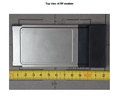
Click to zoom
Application Details
- Equipment Class
- DSS - Part 15 Spread Spectrum Transmitter
- Date of Grant
- Nov 27, 2001
- Application Purpose
- Original Equipment
- Date of Application
- Nov 27, 2001
- Equipment Note
- Wireless LAN PC Card
- Frequency Range
- 2412.00000000 - 2462.00000000
- Company
- Agere Systems Nederland B.V.
- Country
- Netherlands
Documents & Files
Document Text
Text extracted from the exhibit documents filed with the FCC. Open a document above to read the original.
Users Manual
PC Card Quick Start Flyer 017824/A August 2001 Vérifiez le contenu du kitInsérez le CD-ROM Überprüfen Sie den PaketinhaltLegen Sie die CD-ROM ein Verifica il contenuto del kitInserisci il CD-ROM Revise el contenido del kitInserte el CD-ROM Verify Kit ContentsInsert CD-ROM PCC.book Page 1 Thursday, August 9, 2001 7:31 PM Suivez les instructions a.Choisissez votre langue b.Sélectionnez Installation d’un produit. Installez le logiciel c.Sélectionnez Connexion à un réseau sans fil d.Identifiez les paramètres, et installez le pilote et Gestionnaire des Clients Segui le istruzioni visualizate a.Scegli una lingua b.Scegli Installare un prodotto Installa il software c.Scegli Connesione a una rete wireless d.Identifica le impostazioni ed installare il programma Client Manager Siga las instructiones a.Seleccione su idioma b.Seleccione Instalación de un producto Instale el Software c.Seleccione Conexión a una red inalámbrica d.Identifique la configuración e Instale el controlador y Client Manager Follow Instructions on your ScreenInstall Software before Hardware a. Select your language b. Select Install Product c. Select Connect to Wireless Network d. First Identify Settings and next Install Driver and Client Manager Befolgen Sie die Bildschirmanweisungen a.Wählen Sie Ihre Sprache b.Wählen Sie Installieren eines Produktes Installieren Sie der Software c.Wählen Sie Herstellen der Verbindung zu einem Funknetzwerk d.Installieren Sie die Treiber und Client Manager PCC.book Page 2 Thursday, August 9, 2001 7:31 PM Insérez la PC CardUtilisez votre réseau sans fil a.Cliquez ici pour parcourir le CD ou pour retourner a la page prinicpale b.Cliquez ici pour accéder à la table des matières. Setzen Sie den PC Card einFangen Sie an zu Arbeiten mit dem Funknetzwerk a.Benutzen Sie diese Schaltflächer zum navigieren b.Wählen Sie Suchen nach Informationen für CD-Inhalt Inserisci la PC CardInizia ad utilizzare la rete wireless a.Fai clic sul questi pulsanti per percorere il CD. b.Sclegli questo link per trovare più informazioni Inserte PC CardCómo empezar a utilizar la red inalámbrica a.Haga clic en estos botónes para navigar en el sistema e para retomar Home b.Seleccione esto link para más informaciones Insert PC CardStart using your Wireless Network a. Use these buttons to navigate the CD-ROM contents b. Select this link to find more information PCC.book Page 3 Thursday, August 9, 2001 7:31 PM © 2000-2001 Agere Systems Inc., All Rights Reserved. Finding Information ■For more information, insert the CD-ROM into your computer and select “Find Information”. ■For context-sensitive help with the ORiNOCO software, click the Help button or press the [F1] function key. ■For regulatory information, consult the flyer “Information to the User”. ■If you have any problems installing or using this product, contact your Reseller. ■For the latest information, documentation and software updates, visit our website at: http://www.orinocowireless.com. Ulteriori informazioni ■Per ulteriori informazione, inserisci il CD-ROM e sceglie “Ricerca de informazioni”. ■Per attivare la guida contestuale con il software ORiNOCO, fare clic sul pulsante Help oppure premere il tasto funzione [F1]. ■Consultare il documento “Information to the User” per informazioni sulle normative. ■In caso di difficoltà durante l’installazione o l’uso di questo prodotto, contattare il rivenditore. ■Per ulteriori informazioni, e per gli aggiornamenti del software e della documentazione visitare nostro sito web all’indirizzo: http://www.orinocowireless.com. Suchen nach Informationen ■Zu weiteren Informationen legen Sie die CD-ROM ein und wählen Sie “Suchen nach Informationen”. ■Um kontextsensitive Hilfe zu ORiNOCO-Software zu erhalten, klicken Sie auf die Schaltfläche Hilfe oder drücken Sie die Funktionstaste [F1]. ■Zu rechtlichen Bestimmungen lesen Sie bitte das Informationsblatt “Information to the User”. ■Wenn Probleme bei der Installation oder Verwendung dieses Produkts auftreten sollten, wenden Sie sich bitte an Ihren Händler. ■Informationen, aktuelle Software und Dokumentation erhalten Sie auf unser Website unter: http://www.orinocowireless.com. Búsqueda de información ■Para más informaciones, inserte el CD-ROM e seleccione “Cómo buscar información”. ■Si desea acceder a la ayuda sensible al contexto con el software ORiNOCO, haga clic en el botón Help o pulse la tecla [F1]. ■Para obtener información sobre normativas, consulte el folleto “Information to the User”. ■Si tiene problemas al instalar o utilizar este producto, póngase en contacto con su distribuidor. ■Para más informaciones y para obtener las últimas versiones del software y de la documentación, visite nuestro sitio Web en: http://www.orinocowireless.com. Comment trouver des informations? ■Pour ultérieure information, inserez le CD-ROM et selectionnez “Recherche d’Information”. ■Pour une aide en ligne contextuelle avec le logiciel ORiNOCO, cliquez sur le bouton Aide ou appuyez sur touche de fonction [F1]. ■Consulter le dépliant “Information to the User” pour obtenir des informations concernant la réglementation. ■Si vous rencontrez des problèmes lors de l’installation ou de l’utilisation de ce produit, veuillez contacter votre revendeur. ■Pour l’information, la documentation et le logiciel les plus récents consulter notre site web à l’adresse: http://www.orinocowireless.com. PCC.book Page 5 Thursday, August 9, 2001 7:31 PM
Cover Letter(s)
Nederland B.V.____________________________________________________________________________________ (formerly Lucent Technologies Nederland B.V.) Zadelstede 1-10 3431 JZ Nieuwegein The Netherlands Phone: +31 30 6097666 Fax: +31 30 6097556 Federal Communications Commission Authorization & Evaluation Division 7435 Oakland Mills Road Columbia, MD 21046, USA Nieuwegein, 09 November 2001 Re: Request for confidentiality, IMR WLPCE2411R Dear Sir/Madam, Pursuant to 47 CFR 0.457(d) and O/459 we hereby request confidentiality status of Agere Systems documents - no. 017753 (files with schematic drawings used in this application). - no. 017758 (files with parts list drawings) - block diagram and its description Sincerely yours, .............................. Bert Vos, Regulatory Certifications
Cover Letter(s)
American Telecommunications Certification Body Inc. 6731 Whittier Ave, McLean, VA 22101 November 11, 2001 RE: Agere Systems FCC ID: IMRWLPCE2411R Please address the following items on this Application. 1.) Please note the Parts List is not needed on any Part 15 Applications. Do you still wish to have this Exhibit uploaded? 2.) Confidentiality is requested on the Schematics but not for Block Diagram or Parts list. Do you wish for these Exhibits to be included in any Request for Confidentiality? If so, a new letter must be provided. 3.) TCBs are not yet permitted to accept measured SAR data for any device except Part 22 and 24 cellular telephones. If you wish to submit SAR data it must only be done through the FCC application process. To continue with your submission through a TCB you must submit calculated MPE data instead. Attached you will find the TCB RF Exposure Procedures document of November 15, 2000. I recommend you submit as a Transmitter Category VI(b) device, assuming the peak radiated and conducted power does not exceed 50mW. I will be happy to supply further guidance if required. 4.) It is unclear from your Application what antennas are employed. Please provide type, and/or part and model numbers, and antenna gain as part of the RF Exposure exhibit.. 5.) FYI: The test report indicates Processing Gain is not required. This is incorrect. Processing gain continues to be needed on any DSS systems; however non-hopping, non-hybrid DSS systems can qualify as DTS if their power is below 100mW. Since processing gain data is provided I will file as DSS unless advised otherwise. 6.) Please advise if the power reading is with a peak or average meter. 7.) Please separate the Test Setup photos into their own unique and separate Exhibit. This is an FCC requirement for all Part 15 work. 8.) Please demonstrate how the radiated Restricted Band provisions of 15.205 are met, especially the bands 2310 to 2390 MHz, 2483.5 to 2500 MHz, and any harmonics which may fall within the table listed in this section.. 9.) Please define the antenna connector used per 15.203. Please provide clear photographs of antennas used with this device. 10.) Measured power output shows ~13.6dBm. Requested power on 731 shows +15dBm. It is FCC policy to use measured values. Please advise. William H. Graff Examining Engineer President and Director of Engineering mailto:[email protected] The items indicated above must be submitted before processing can continue on the above referenced application. Failure to provide the requested information may result in application termination. Correspondence should be considered part of the permanent submission and may be viewed from the Internet after a Grant of Equipment Authorization is issued. Please do not respond to this correspondence using the email reply button. In order for your response to be processed expeditiously, you must submit your documents through the AmericanTCB.com website. Also, please note that partial responses increase processing time and should not be submitted. Any questions about the content of this correspondence should be directed to the sender.
Cover Letter(s)
EMV-Prüfzentrum EMI/EMC-Testcenter FCC-ID: IMRWLPCE2411RAddendum 1 to Test Reports No. 56305-10552-1/-3 Page 1 of 1 Page(s) Straubing, November 9, 2001 Maximum Peak Output Power Measurement (§ 15.247.b) The maximum peak output power was measured with a power meter connected to the antenna connector (conducted measurement) while EUT was operating in transmit mode at the appropriate center frequency. The correction factor noted on the test records is caused by the attenuation of the adapter cable between antenna connector and power sensor in addition to the attenuation of the DC block. The maximum power values were recorded. Test equipment used: No. TypeModelSerial NumberManufacturer 08Power MeterNRVS836856/015Rohde & Schwarz 09Power SensorNRV-Z52837901/030Rohde & Schwarz 67Cable for Antenna ConnectorAgere 68DC Block 0.01-18GHz8037Inmet Corp. Note 1: The power sensor NRV-Z52 manufactured by Rohde & Schwarz is a thermocouple sensor which is indicating the RMS power. Note 2: The duty cycle of the EUTs documented in test reports no. 56305-10552-1 and 56305-10552-3 is > 99%
Cover Letter(s)
'a'3013442050 07/25/96 16:44 ~OOl FCC LAB FEDERAL COMMUNICATIONS COMMISSION Equipment Authorization Division,Application Processing Branch 7435 Oakland Mills Road, Columbia, MD 21046 Telephone: (301) 725-1585,ext 230 Facsimile: (301) 344-2050 DATE:O72596 FROM: Gregory M. Czumak REFERENCE: your fax dated 19JUL96 NO. OF PAGES: one TO: Bert Vos ORGANlZA TION:Lucent Dear Bert: This is in response to your fax dated July 19, 1996. From the information provided, it appears that the proposed antenna connector does comply with Section 15.203. If you have additional questions on this subject, please do not hesitate to contact me by fax or phone. c..C-~ ~ ,SV\-to(et..b~ W. K~Uo¥ '9607/18 14:26z 31 332534512 RADIAL 01 ~Th further to yQU1' fax dated Ju1y 16 we hereby submit our reaclion. T<1 m~ un IS it ] thc wc I begin with we want to thank you for including the excerpt from the FCC text, because it fKes it clear to us that you have a serious worry .However, from it we can not establish imbiguousJy whether or not we comply, because as you already stated the definition of what ;tandard is not unambiguous. We can say, with regard to the MC-card co1Ulector series, that a proprietary Radiall design. It is not in any way standardized and it is our experience that type of application it is intended for, nearly always requires specialized dcsigns, which ,old mean that it is not in our interest to pursue normalization. thE Wi ph uru if im dc' Wc WJIbest regards. i/)/:J £ V,lt;I1'~. Marc Teeuwissen, technical sales support.
Cover Letter(s)
FCC ID: IMRWLPCE2411R DA 001407 Identified Points Answers for this application 1. The modular transmitter must have its own RF shielding. This is intended to ensure that the module does not have to rely upon the shielding provided by the device into which it is installed in order for all modular transmitter emissions to comply with Part 15 limits. It is also intended to prevent coupling between the RF circuitry of the module and any wires or circuits in the device into which the module is installed. Such coupling may result in non-compliant operation. Product has its own RF shielding. 2. The modular transmitter must have buffered modulation/data inputs (if such inputs are provided) to ensure that the module will comply with Part 15 requirements under conditions of excessive data rates or over-modulation. Yes 3. The modular transmitter must have its own power supply regulation. This is intended to ensure that the module will comply with Part 15 requirements regardless of the design of the power supplying circuitry in the device into which the module is installed. Product has power regulator from 5Vdc to 3.3Vdc 4. The modular transmitter must comply with the antenna requirements of Section 15.203 and 15.204(c). The antenna must either be permanently attached or employ a “unique” antenna coupler (at all connections between the module and the antenna, including the cable). Any antenna used with the module must be approved with the module, either at the time of initial authorization or through a Class II permissive change. The “professional installation” provision of Section 15.203 may not be applied to modules. The Product has unique antenna connector. 5. The modular transmitter must be tested in a stand-alone configuration, i.e., the module must not be inside another device during testing. This is intended to demonstrate that the module is capable of complying with Part 15 emission limits regardless of the device into which it is eventually installed. Unless the transmitter module will be battery powered, it must comply with the AC line conducted requirements found in Section 15.207. AC or DC power lines and data input/output lines connected to the module must not contain ferrites, unless they will be marketed with the module (see Section 15.27(a)). The length of these lines shall be length typical of actual use or, if that length is unknown, at least 10 centimeters to insure that there is no coupling between the case of the module and supporting equipment. Any accessories, peripherals, or support equipment connected to the module during testing shall be unmodified or commercially available (see Section 15.31(i)). Product has been tested in test jig, connected to a PC. 6. The modular transmitter must be labeled with its own FCC ID number, and, if the FCC ID is not visible when the module is installed inside another device, then the outside of the device into which the module is installed must also display a label referring to the enclosed module. This exterior label can use wording such as the following: “Contains Transmitter Module FCC ID: XYZMODEL1” or “Contains FCC ID: XYZMODEL1.” Any similar wording that expresses the same meaning may be used. The Grantee may either provide such a label, an example of which must be included in the application for equipment authorization, or, must provide adequate instructions along with the module which explain this requirement. In the latter case, a copy of these instructions must be included in the application for equipment authorization. Product will bear the label with the above FCC ID 1 of 2 FCC ID: IMRWLPCE2411R 7. The modular transmitter must comply with any specific rule or operating requirements applicable to the transmitter and the manufacturer must provide adequate instructions along with the module to explain any such requirements. A copy of these instructions must be included in the application for equipment authorization. For example, there are very strict operational and timing requirements that must be met before a transmitter is authorized for operation under Section 15.231. For instance, data transmission is prohibited, except for operation under Section 15.231(e), in which case there are separate field strength level and timing requirements. Compliance with these requirements must be assured. No spcific requirements. There is a manual too. 8. The modular transmitter must comply with any applicable RF exposure requirements. For example, FCC Rules in Sections 2.1091, 2.1093 and specific Sections of Part 15, including 15.319(i), 15.407(f), 15.253(f) and 15.255(g), require that Unlicensed PCS, UNII and millimeter wave devices perform routine environmental evaluation for RF Exposure to demonstrate compliance. In addition, spread spectrum transmitters operating under Section 15.247 are required to address RF Exposure compliance in accordance with Section 15.247(b)(4). Modular transmitters approved under other Sections of Part 15, when necessary, may also need to address certain RF Exposure concerns, typically by providing specific installation and operating instructions for users, installers and other interested parties to ensure compliance. Yes, see Statement included in the application package. 9. If compliance with one or more of the numbered requirements, listed above, cannot be demonstrated, it may be possible to obtain a “Limited Modular Approval” (LMA). This will be issued in those instances where the Grantee can demonstrate that it will retain control over the final installation of the device, such that compliance of the end product is assured. In such a case, an operating condition on the grant of equipment authorization for the module would state that the module is only approved for use when installed in devices produced by a specific manufacturer, typically the Grantee. If LMA is sought, the application for equipment authorization must make this fact clear. It must also specifically state how control of the end product, into whic…
Text truncated - open the document above for the full version.
Cover Letter(s)
Nederland B.V._________________________________________________________________________________ (formerly Lucent Technologies Nederland B.V.) Zadelstede 1-10 3431 JZ Nieuwegein The Netherlands Phone: +31 30 6097666 Fax: +31 30 6097556 American TCB, Inc. 6731 Whittier Avenue McLean, VA 22101 USA Nieuwegein, 13 November 2001 Re: FCC ID: IMRWLPCE2411R Reaction to questions dated November 11, 2001 Dear Sir/Madam, Reaction/answers to the questions: 1. Until last time with FCC Parts list was always required. We wish to keep it in the file. 2. Yes, we would like to include the other items and a new letter will be provided (Conf letter 2 LETAgere (Luc).pdf 3. In principle the application package consists of 2 parts, one for the PC Card with Integral antenna, and some additional information to cover also use of specific external antennae (see attachment A). The card with integral antenna has rated output power of 32 mW e.i.r.p. and according to your information a SAR report would not be required. We will send a new RF Exposure Compliance paper covering both applications, but still would like to have the available SAR report uploaded to FCC as additional information. Please withdraw the previously sent RF Exposure document. 4. The new RF Exposure Compliance(_3) paper contains the antennae information. 5. Text in report that Processing Gain is not required is incorrect and will be removed. A new report will be made but please use the current one now for FCC. 6. Peak power measurement is explained in additional paper from Senton (010552_Power measurement.pdf) 7. A separate file from Senton with photos taken during testing (010552_1_Annex B.pdf) will be sent. 8. In report 01552-1 in sections 7.5 and 7.6 the test methods indicate compliance to 15.205. Also please check e.g. page 110 of the report where results are shown and indication is given whether high level is in restricted band or else. 9. Attached are some pages on the antenna connector we (still) use (connector 2.pdf). 10. I assume your data on power output comes from page 39 of report 56305-01552-1. The value 13.6 dBm is meter reading, but a correction factor has been added in the table and the final value is then 14.7 dBm. On form 731 the RATED value is required and we think 15 dBm is then correct. Sincerely yours, Bert Vos, Regulatory Certifications Attachment A FCC ID: IMRWLPCE2411R Explanation of complete package: 1. Basic application Is for PC Card Extended with Integral TX antenna. This antenna has gain of 0 dBi. The report for this application is no. 56305-10552-1 2. Extended application Is for use of same card with external antennae (Range Extender) with following characteristics: - model AIN24-OD-0202, omni-directional type with gain of 2.5 dBi - model AIN24-OD-03, omni-directional type with gain of 3 dBi Package contains extra report (no. 56305-10552-3) giving extra test results Notes: - RF Exposure Statement covers both Integral and External Antennae
External Photos
FCC ID: IMRWLPCE2411R PHOTOS OF THE PRODUCT 1. PHOTOS OF EXTERNAL OF PRODUCT PC CARD
ID Label/Location Info
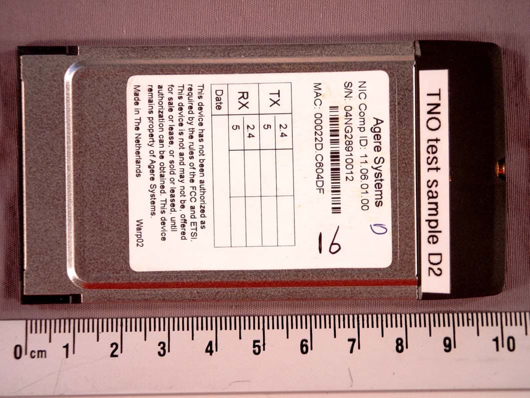
FCC ID: IMRWLPCE2411R LABEL CONTENTS AND PLACEMENT
Internal Photos
FCC ID: IMRWLPCE2411R 1. PHOTOS OF INTERNAL OF PRODUCT PC CARD
Operational Description
NederlandB.V. August 2001 DESCRIPTION ORINOCO IEEE PC Card Extended High Speed (FC) This ORINOCO IEEE PC Card product provides a ORINOCO compatible wireless connection for portable and mobile computers in accordance with IEEE standard 802.11 DSSS. It can work at 11, 5.5, 2 or 1 Mbps. The operation is in accordance with IEEE 802.11. The product, one piece of hardware, contains the following blocks: - PCMCIA interface - Wireless Medium Access Control (WMAC); this chip is used for handshaking with the PCMCIA bus and for handling the IEEE protocol; it also does frequency management and interfaces to FlashROM for parameters on frequencies and Call codes. Here also selection for 11, 5.5, 2 or 1 Mbps is handled. - Digital signal processor takes care of all modulation/demodulation for DSSS for all above rates and can do selection out of 2 receiving antennae - Antenna function, provides a diversity antenna and connection to optional external antenna. It provides two antenna elements, one for transmitting while one of the two can be selected for reception. Optionally it can be equipped with: - a factory installable data encryption feature (WEP), and Block Diagram DIGITAL SIGNAL PROCESSOR WMAC Antenna Conn . PCMCIA Interface Connector The technical specification is as follows on the next page. NederlandB.V. Aug01 TECHNICAL SPECIFICATION ORINOCO IEEE PC Card Extended High Speed (FC) 2.4 GHz Data Signalling Rate: 11, 5.5, 2 or 1 Mbit/s Media Access Protocol: According to IEEE 802.11 DSSS, CSMA/CA (Collision Avoidance) Bit Error Rate: Better than 10-8 Base-Band Modulation: - 2 Mbps: Differential Quadrature Phase Shift (before spreading) Keying (DQPSK) 2 bits/symbol - 11 and 5.5 Mbps: Complementary Code Keying Differential Quadrature Phase Shift Keying (DQPSK CCK) Spread Spectrum: Direct Sequence with 11 chips/symbol interval. Pseudo random Barker code sequence: { 1 -1 1 1 -1 1 1 1 -1 -1 -1 } Chipping Rate: 11 Mchips/s Carrier Frequency: Selectable from factory pre-programmed set according to IEEE 802.11: 2412, 2417, 2422, 2427, 2432, 2437, 2442, 2447, 2452, 2457 and 2462 MHz Peak Output Power: < 32 mW rms power (15 dBm) RF Power Density: < 8 dBm/3kHz or <10 dBm/MHz Antenna (indoor): Integral, Omni-Directional (OD): - Gain 0 dBi - Polarization diversity Hor/Vert External, e.g. Range Extender AIN24-OD-0202: - Gain 0 dBi - Polarization diversity Hor/Vert. Spurious Emissions etc: - Satisfies the USA Federal Comm. Commission (FCC) rules Part 15.247 - Satisfies the EU requirements to EN 300 328
Test Report
EMV-Pr ̧fzentrum EMI/EMC-Testcenter Page 1 of 157 Pages Straubing, September 5, 2001 T E S T - R E P O R T No. 56305-10552-1 for PC24E-11-FC/R RF-modem for wireless LAN Applicant:Agere Systems Nederland B.V. Purpose of testing:To show compliance with FCC Code of Federal Regulations, Part 15 Subpart C, Section ß15.247 Note: The test data of this report relate only to the individual item which has been tested. This report shall not be reproduced except in full extent without the written approval of the testing laboratory. EMV-Pr ̧fzentrum EMI/EMC-Testcenter FCC-ID: IMRWLPCE2411RTest Report No. 56305-10552-1 Page 2 of 157 Pages Table of Contents 1. Administrative Data ............................................................................................. 3 2. Identification of Test Laboratory .......................................................................... 4 3. Summary of Test Results .................................................................................... 5 4. Operation Mode of EUT....................................................................................... 6 5. Configuration of EUT and Peripheral Devices ..................................................... 7 6. Setup of Host....................................................................................................... 8 7. Measuring Methods ............................................................................................. 9 7.1. Minimum 6 dB Bandwidth (ß 15.247.a2) ..................................................... 10 7.2. Maximum Peak Output Power (ß 15.247.b) ................................................ 11 7.3. Peak Power Density (ß 15.247.d) ............................................................... 11 7.4. Conducted Emission 0.45 MHz - 30 MHz (ß15.207) ................................... 12 7.5. Radiated Emission 30 MHz - 1 GHz (ß15.209, ß15.247.c, ß15.205.a,b) ............................................................................................... 14 7.6. Radiated Emission 1 GHz - 25 GHz (ß15.209, ß15.247.c, ß15.205.a,b) ............................................................................................... 16 8. Equipment List................................................................................................... 18 9. Photographs Taken During Testing ................................................................... 20 10. List of Measurements ........................................................................................ 26 11. Test Results ...................................................................................................... 28 EMV-Pr ̧fzentrum EMI/EMC-Testcenter FCC-ID: IMRWLPCE2411RTest Report No. 56305-10552-1 Page 3 of 157 Pages 1.Administrative Data Equipment Under Test (EUT):PC24E-11-FC/R Serial number(s):01UT33300016 Type of equipment:RF-modem using DSSS technology for wireless connection for e.g. portable and mobile computers which have a PC-card-bus (PCMCIA). Parts/accessories:see "Configuration of EUT and Peripheral Devices" on page 7 FCC-ID:IMRWLPCE2411R Applicant:Agere Systems Nederland B.V. (full address)Zadelstede 1-10 NL-3431 JZ Nieuwegein The Netherlands Contract identification:--- Contact person:Mr. Wout Kerkhof Manufacturer:Agere Systems Nederland B.V. Receipt of EUT:August 21, 2001 Date of test:August 24 to September 5, 2001 Note:--- Responsible for testing:Rainer Heller Responsible for test report:Rainer Heller EMV-Pr ̧fzentrum EMI/EMC-Testcenter FCC-ID: IMRWLPCE2411RTest Report No. 56305-10552-1 Page 4 of 157 Pages 2.Identification of Test Laboratory Test Laboratory:Senton GmbH EMI/EMC Test Center (full address):Aeussere Fruehlingstrasse 45 D-94315 Straubing Germany Contact person:Mr. Johann Roidt Communication:Telephone(+49) 0 94 21 / 55 22-0 Fax (+49) 0 94 21 / 55 22-99 eMail:[email protected] FCC registration number:90926 Industry Canada file number:IC 3050 EMV-Pr ̧fzentrum EMI/EMC-Testcenter FCC-ID: IMRWLPCE2411RTest Report No. 56305-10552-1 Page 5 of 157 Pages 3.Summary of Test Results The tested sample complies with the requirements set forth in the Code of Regulations Part 15 Subpart C, Section ß15.247 (intentional radiators) of the Federal Communication Commission (FCC). Johann RoidtRainer Heller Technical ManagerTest Engineer EMV-Pr ̧fzentrum EMI/EMC-Testcenter FCC-ID: IMRWLPCE2411RTest Report No. 56305-10552-1 Page 6 of 157 Pages 4.Operation Mode of EUT All tests were performed using the "WaveLAN-II Engineering Test Program", Version v02.23 (Aug 22 2001). According to applicant three different kinds of modulation are used for transmission specified by the appropriate bit rate: Transmit mode (TX): Operating frequencyRated output power (conducted) [dBm]Test [GHz]Bit rate 2 MbpsBit rate 5.5 MbpsBit rate 11 Mbps performed 1 2.412+15+15+15X 2.417+15+15+15 2.422+15+15+15 2.427+15+15+15 2.432+15+15+15 2.437+15+15+15 2.442+15+15+15X 2.447+15+15+15 2.452+15+15+15 2.457+15+15+15 2.462+15+15+15X Receive mode (RX): Operating frequency [GHz] Test performed 2.412 2.417 2.422 2.427 2.432 2.437 2.442X 2.447 2.452 2.457 2.462 1 Full testing with bit rate 11 Mbps only EMV-Pr ̧fzentrum EMI/EMC-Testcenter FCC-ID: IMRWLPCE2411RTest Report No. 56305-10552-1 Page 7 of 157 Pages 5.Configuration of EUT and Peripheral Devices RF-modem module PC24E-11-FC/R was tested operating with internal antenna and mounted in PC-card slot of notebook AT & T Globalyst 200 via PC-card extender (RF- modem module completely outside the notebook). This setup was selected to test the EUT as a modular device. In table 1 used accessories and host equipment are listed (with Agere part numbers). ItemModel or part no. Serial no.DesignationManufacturer RF-modem01512401UT33300016PC24E-11-FC/RAgere PC-card extender 2 ---C050A-9000PCCextend 50ASycard Technology Notebook---017-28730433Globalyst 200AT & T AC adapter---9411AC adapter 3150-K909-V001 AT & T Table 1: EUT and accessories 2 Shielding improved by connecting housing of PC-card …
Text truncated - open the document above for the full version.
Test Report
EMV-Prüfzentrum EMI/EMC-Testcenter Page 1 of 96 Pages Straubing, October 8, 2001 T E S T - R E P O R T No. 56305-10552-3 for PC24E-11-FC/R RF-modem for wireless LAN Applicant:Agere Systems Nederland B.V. Purpose of testing:To show compliance with FCC Code of Federal Regulations, Part 15 Subpart C, Section §15.247 Note: The test data of this report relate only to the individua…
Text truncated - open the document above for the full version.
Contact Information
Applicant
Maarten Visee(Hardware/Development Manager)
Test Firm
TUV SUD Product Service GmbH PS-EMC-STRRainer Heller
Technical Specifications
| # | Rule Parts | Frequency Range | Power Output |
|---|---|---|---|
| 1 | 15C | 2.41 GHz - 2.46 GHz | 32.00 mW |
Other Applications from Agere Systems Nederland B.V.
IMR1106CB
Oct 25, 20042.4/5 GHz IEEE 802.11g/a WLAN Cardbus card
Equipment Class
NII - Unlicensed National Information Infrastructure TX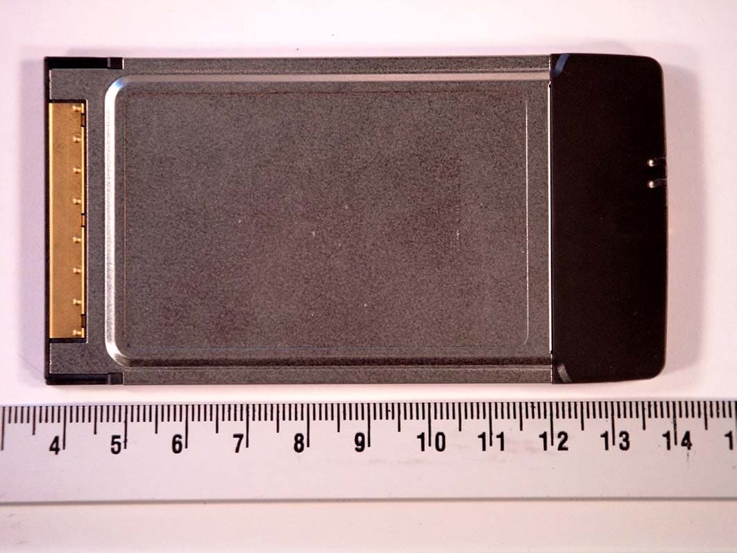
IMR1102CB
Jul 08, 2004IEEE 802.11 a/b/g CardBus Card
Equipment Class
NII - Unlicensed National Information Infrastructure TX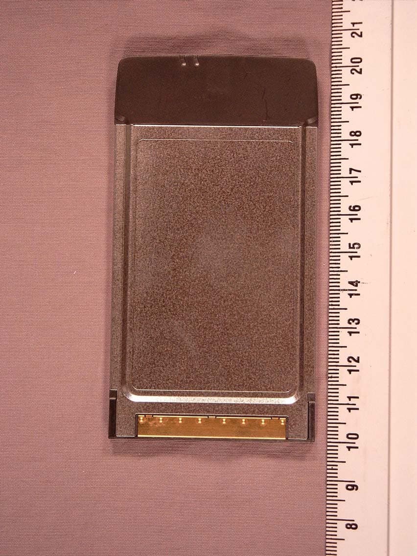
IMR1103CB-D
Jul 01, 2004IEEE 802.11 a/b/g CardBus Card
Equipment Class
NII - Unlicensed National Information Infrastructure TX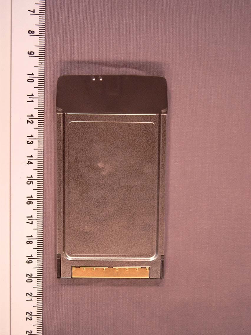
IMRCB1102
Mar 28, 2004IEEE 802.11 a/b/g CardBus Card
Equipment Class
DTS - Digital Transmission System
IMRPC2411B
Dec 11, 2002Wireless LAN PC Card 2.4 GHz
Equipment Class
JBP - Part 15 Class B Computing Device Peripheral