IVS1000TRRemote Control Transmitter
Touchtronics Inc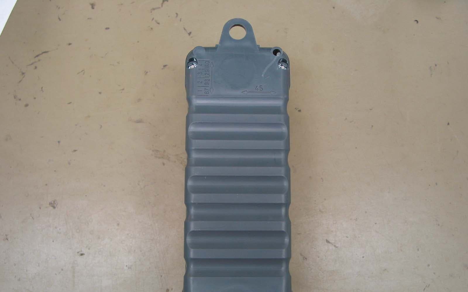
Click to zoom
Application Details
- Equipment Class
- DSC - Part 15 Security/Remote Control Transmitter
- Date of Grant
- Apr 20, 2010
- Application Purpose
- Original Equipment
- Date of Application
- Apr 20, 2010
- Equipment Note
- Remote Control Transmitter
- Frequency Range
- 433.90000000 - 433.90000000
- Company
- Touchtronics Inc
- Country
- United States
Documents & Files
Document Text
Text extracted from the exhibit documents filed with the FCC. Open a document above to read the original.
Users Manual
Radio Frequency (RF) Remote Control System Service Manual POWERTouch 1200 Manual NST11424-2 2010-04-05 Rev F 57315 Nagy Drive Elkhart, IN 46517 TTIouchronics, nc. Ph: 800-294-2570 Fx: 574-293-1611 www.touchtronics.com [email protected] 1230-R Harness w/ Sealing Gasket Sealed Receiver: Moisture & Dust Model # P12xx-R Sealed (see pg 2 for model number chart) Range - 300 Feet Typical - Up to 600 Feet Output - 4 Relays Optional - 7 Relays Input - 2 (+12v) A1 & A2 Optional - 6 (+12v or Ground) B1 - B6 . Frequency - 433MHz Codes - Rolling Codes - Secure Encryption Voltage - 12VDC - 24VDC Current - 5 Amps Max per Output - 10 Amp Input - Standard - 30 Amp Input - Optional Antenna - Fixed - Standard (shown) Optional - TNC Whip - Flex Whip / Roof Mount - Flex Whip / Glass Mount Harness - 9” Standard, 14 pin Battery - All transmitter styles (except TR style) - Coin Style, Lithium, CR2032 - 100,000 1-second pulses - 10 year shelf life - TR Style - 2 x “AA” Batteries System Specifications P1000-TM1P1000-TM2P1000-TM4 P1000-TK1P1000-TK2P1000-TK4 P1000-TF2P1000-TF2-LKP1000-TF4 P1000-TX2P1000-TX4P1000-TX6 P1000-TX2SP1000-TX4SP1000-TX6S No ON/OFF Switch With ON/OFF Switch P1000-TF6 TK, TF & TR Series Sealed Transmitters P1000-TR4P1000-TR3P1000-TR2 Receiver Installation Determine mounting location of receiver and antenna - typically under the dash or behind a wall. Antenna Installation 1. The antenna must be installed in an open, non-metal area in order to receive RF (radio frequency) transmissions. 2. Antenna range will be reduced if located: A) within 6 feet of a large motor B) near large bundles of wires C) near other RF devices D) touching any metal To Increase Antenna Range A) Install exterior mount NMO Antenna See page 4 for accessory antenna options Each time a button is pressed on the transmitter, the corresponding output will turn On. For example, if button #1 is pressed, output #1 will turn On as long as the button is held. If an input signal is sent to inputs A1 or A2, or any inputs B1 - B6, the corresponding output will turn On as long as the signal is present. (A1 or B1 = Output #1 is ON. A2 or B2 = Output #2 is ON) Each output is factory set as momentary. To change output from momentary to latching (push on / push off) see DIP Switch options detail on page 3. ENROLLING NEW TRANSMITTERS - Self-Learning Receiver 1. Remove and reconnect power to unit. This will place unit into LEARN mode for 5-seconds. 2. Press any button on transmitter once. Wait 5-seconds and confirm the transmitter has been enrolled by pressing any button and verifying the correct output turned ON. OR 1. Remove cover from receiver enclosure. 2. Locate LEARN switch (*small, push-button style switch located in the corner of the printed circuit board). 3. Press and release the LEARN switch The Red LEARN LED next to the switch will flash 4. Press any button on NEW transmitter. 6. Red LEARN LED double blinks to confirm enrollment. 7. Press any button on the new transmitter to confirm that the new transmitter code has been enrolled. 8. Replace receiver enclosure cover. Erasing Enrolled Codes 1. Press and hold the LEARN switch (*see # 2 above) for 10-seconds. 2. Red status LED will flash while holding LEARN switch 3. Release LEARN switch when Red LED double flashes to confirm ALL transmitter codes are erased. System Operation Code Enrollment Installation 1210-R 1211-R 1212-R 1213-R 1220-R 1221-R 1222-R 1223-R 1230-R 1231-R 1232-R 1233-R 1240-R 1241-R 1242-R 1243-R Receiver Model 4 - Relays7 - Relays12VDC24VDC30AConnectorFixedAntennaTNCAntennaA1 & A2 Switch InputsB1 - B6 Switch InputsInputStatus LEDs Sealed Receiver Model Number Chart Page -2- ON OFF 1 Out# 1 DIP Switch Options (DIP switch located on PCB inside receiver enclosure) ONOFF Out# 3 Out# 2 Out# 4 Out# 5 Out# 6 2 3 4 5 6 7 8 DIP Switches 1 - 6 control outputs 1 - 6 respectively: OFF = Momentary (Standard) ON = Latching (Optional) #10 Screw #10 Star W asher #10 Ring T erminal V ehicle Frame Scrape paint and clean area before installing ground screw . A loose chassis gr ound connection WILL cause intermittent operation! Call factory for more information on other DIP switch options, including hydraulic pump, cascade and courtesy lights. ANTENNA (FIXED or TNC) Output 1J2-8Output 2J2-9Output 3J2-10Output 4J2-1 1 Output 6J2-13Output 5J2-12Output 7J2-14 Switch Input A2, J2-2 Switch Input A1, J2-1 Logic Power , J2-4 Logic Ground, J2-3 LOGIC 123456789 10 1 1 121314 12123456 WHT/REDGR Y/RED BLK/WHTRED/WHTNOT USED REDREDYELORGBLUGRNPNKVIOT AN REDNOT USED YEL/BLKORG/BLKBLU/BLKGRN/BLKPNK/BLKVIO/BLK +12V / A1 +12V / A2 CHASSIS GROUND+12V LOGIC POWERPOWER / 5 AMP POWER / 5 AMP OUTPUT 1 - 5 AMP (+) OUTPUT 2 - 5 AMP (+) OUTPUT 3 - 5 AMP (+) OUTPUT 4 - 5 AMP (+) OUTPUT 5 - 5 AMP (+) OUTPUT 6 - 5 AMP (+) OUTPUT 7 - 5 AMP (+) POWER / 30 AMP +12v or GND / B1+12v or GND / B2+12v or GND / B3+12v or GND / B4+12v or GND / B5+12v or GND / B6 ST ANDARD RELA YS 1-4 OPTIONALRELA YS 5-7 J3J2J1 ALL INPUTS, B1-B6, ARE LOGIC SIGNALS (1mA)ACTIVE WITH EITHER+12V OR GROUND. INPUT A1, A2 Logic Signals (1mA) BA TTER Y BA TTER Y 10 AMP BA TTER Y 30 AMP Optional / Customer Supplied Optional / Customer Supplied Output 7Used only with DIP Switch Option 7 & 8 Call Factory for Custom Applications T ouchT ronics, Inc. 1-800-294-2570 BA TTER Y All output signals can be either +12VDC or Ground. For +12VDC output signals, supply +12vdc to: J1-1, J2-6 and J2-7 For Ground output signals, supply +12vdc to: J1-1 and J2-7 Page -3- 123456789 10 1 1 121314 12123456 SealingGasket Limited One (1) Year Warranty 1) Each individual product is warranted under the TouchTronics Limited Warranty program for 1 full year from date of purchase or a maximum of 2 years from the date of manufacture. 2) No product will be covered under the TouchTronics Limited Warranty program that has a manufacture date older than 2 years. 3) To receive technical support or warranty service, call our technical support center during regular busines…
Text truncated - open the document above for the full version.
Cover Letter(s)
TouchTronics, Inc. 57315 Nagy Drive www.touchtronics.com ph: 800-294-2570 Elkhart, IN 46517 [email protected] fx: 574-293-1611 FCC ID: IVS1000TR IC: 6265A-1000TR Request for Confidentiality In accordance with United States 47 C.F.R. Section 0.459 and Industry Canada RSP-100 Section 10, we, TouchTronics, Inc., hereby request confidentiality for the schematic diagrams, part lists, and component specifications presented for certification. In support of the Request for Confidentiality, the following is stated: Enclosed within this application is technical information which we deem to be trade secrets and proprietary. If made public, the information might be used to our disadvantage. To assist in assuring that we receive the full value of our product and protect its competitive posture, we respectfully request this grant of confidentiality. Regards, Alice E. Poseley President April 6, 2010 ______________________ Date
ID Label/Location Info
Label and Location for IVS1000TR Label artwork (2 x actual size): Label Size: 1” x 0.75” The label is placed on the outer back side of the hand-held unit and on the inner back side:
Test Report
Amber Helm Development L.C. 92723 Michigan Hwy-152 Sister Lakes, MI 49047 A copy of this Report will be on file with AHD to: March, 2020 Page 1 of 25 EMC Test Report #1001328FX Issued 04/09/2010 Regarding the FCC Part 15, SubPart C testing 4 Button Transmitter Model Number: P1000-TR Category: Periodic Intentional Radiator Judgments: FCC Part 15 Part 15.231 – Compliant Industry Canada RSS-210 Issue 7, ICES-003 and RSS-Gen - Compliant NVLAP LAB CODE 200129-0 Prepared for: Ron Mathia TouchTronics 57315 Nagy Dr. Elkhart, IN 46517 Test Date(s): 2/10/10-3/23/10 Report prepared by: Report reviewed by David J. Miller, NCE Gordon L. Helm, NCE Data recorded by: _________________________ Gordon L. Helm, NCE Test Engineer, AHD Test report # 1001328 Tested 2/10/10-3/23/10 FCC 15.231 for 4 Button Transmitter AHD EMC Lab, 92723 Michigan Hwy-152, Sister Lakes, MI 49047 (269) 429-8352 Page 2 of 25 Table of Contents Statements concerning this report ....................................................................................................3 FCC Required user statements:........................................................................................................4 Industry Canada Required user statements: .....................................................................................5 Summary of Results .........................................................................................................................6 Changes Made to Achieve Compliance:....................................................................................... 7 EUT Descriptions.............................................................................................................................7 Specifications:............................................................................................................................... 7 Input Power: 2 AA batteries .....................................................................................................7 Outputs Signals: 434 MHz Pulse Modulation ......................................................................... 7 EUT Block Diagram: .................................................................................................................... 7 EUT Pictures ................................................................................................................................. 8 Equipment Test Setup: .....................................................................................................................9 Support Equipment & Cabling...................................................................................................... 9 Setup Pictures.............................................................................................................................. 10 Measurement Report ......................................................................................................................13 Standards Applied to Test ........................................................................................................... 13 Equipment Configuration............................................................................................................ 13 Test Methodology ....................................................................................................................... 13 Radiated: ................................................................................................................................. 13 Variance from Test Procedure: ............................................................................................... 13 Test Data ..................................................................................................................................... 14 Radiated Spurious Emissions:................................................................................................. 14 Radiated Transmit Emissions ................................................................................................. 14 Environment................................................................................................................................ 18 APPENDIX A ................................................................................................................................19 Measurement Procedures ............................................................................................................ 19 Line Conducted ....................................................................................................................... 19 Radiated .................................................................................................................................. 20 Measurement Facilities & Equipment ........................................................................................ 21 Cable Loss................................................................................................................................... 21 Antenna Factors .......................................................................................................................... 23 AHD Accreditation ..................................................................................................................... 24 NARTE Seal.......................................................................................................................... 25 Test report # 1001328 Tested 2/10/10-3/23/10 FCC 15.231 for 4 Button Transmitter AHD EMC Lab, 92723 Michigan Hwy-152, Sister Lakes, MI 49047 (269) 429-8352 Page 3 of 25 Statements concerning this report NVLAP Accreditation: NVLAP Lab Code 200129-0 The scope of AHD accreditation are the test methods of: IEC/CISPR 22: Limits and methods measurement of radio disturbance characteristics of information technology equipment. FCC Method – 47 CFT Part 15: Digital Devices. AS/NZS 3548: Electromagnetic Interference – Limits and Methods of Measurement of Information Tec…
Text truncated - open the document above for the full version.
Test Setup Photos
Test report # 1001328 Tested 2/10/10-3/23/10 FCC 15.231 for 4 Button Transmitter AHD EMC Lab, 92723 Michigan Hwy-152, Sister Lakes, MI 49047 (269) 429-8352 Page 10 of 25 Setup Pictures • Radiated Prescreen Setup Page 11 • Radiated Setup Front View Page 11 • Radiated Setup Rear View Page 12 • Transmit Setup Flat Orientation Page 12 • Transmit Setup Side Orientation Page 13 • Transmit Setup End Orientation Radiated Prescreen Setup Radiated Setup Front View Test report # 1001328 Tested 2/10/10-3/23/10 FCC 15.231 for 4 Button Transmitter AHD EMC Lab, 92723 Michigan Hwy-152, Sister Lakes, MI 49047 (269) 429-8352 Page 11 of 25 Radiated Setup Rear View Transmit Setup Flat Orientation Test report # 1001328 Tested 2/10/10-3/23/10 FCC 15.231 for 4 Button Transmitter AHD EMC Lab, 92723 Michigan Hwy-152, Sister Lakes, MI 49047 (269) 429-8352 Page 12 of 25 Transmit Setup Side Orientation Transmit Setup End Orientation
Contact Information
Applicant
David W Evans(Senior Design Engineer)
Test Firm
AHD EMC LaboratoryGordon Helm
Technical Specifications
| # | Rule Parts | Frequency Range | Power Output |
|---|---|---|---|
| 1 | 15.231 | 433.9 MHz - 433.9 MHz | - |
Other Applications from Touchtronics Inc
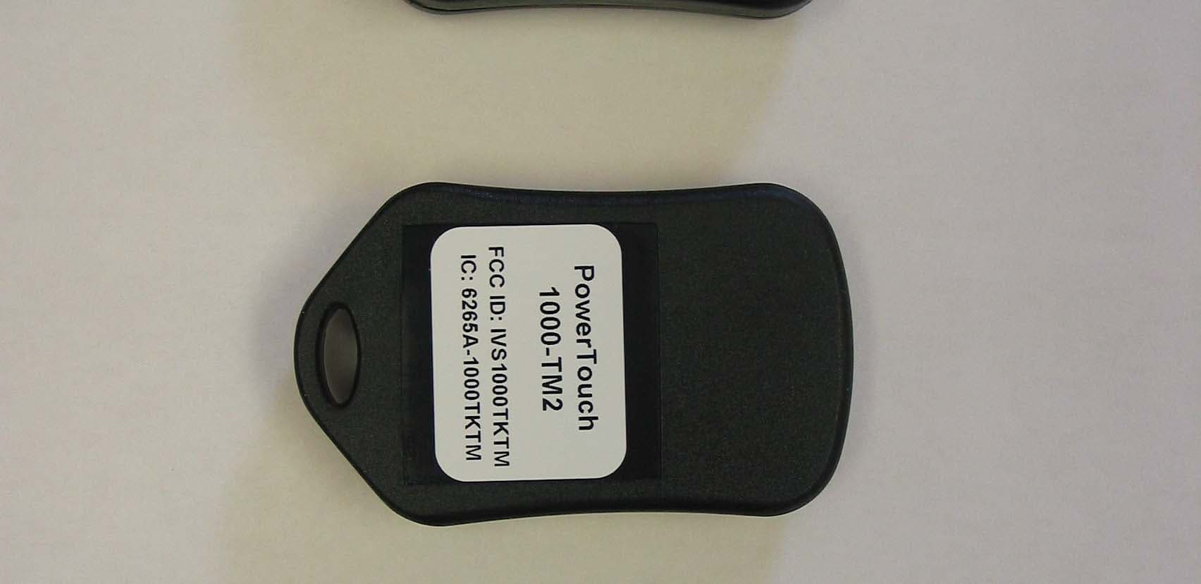
IVS1000TKTM
Mar 24, 2008Security/Remote Control Transmitter
Equipment Class
DSC - Part 15 Security/Remote Control Transmitter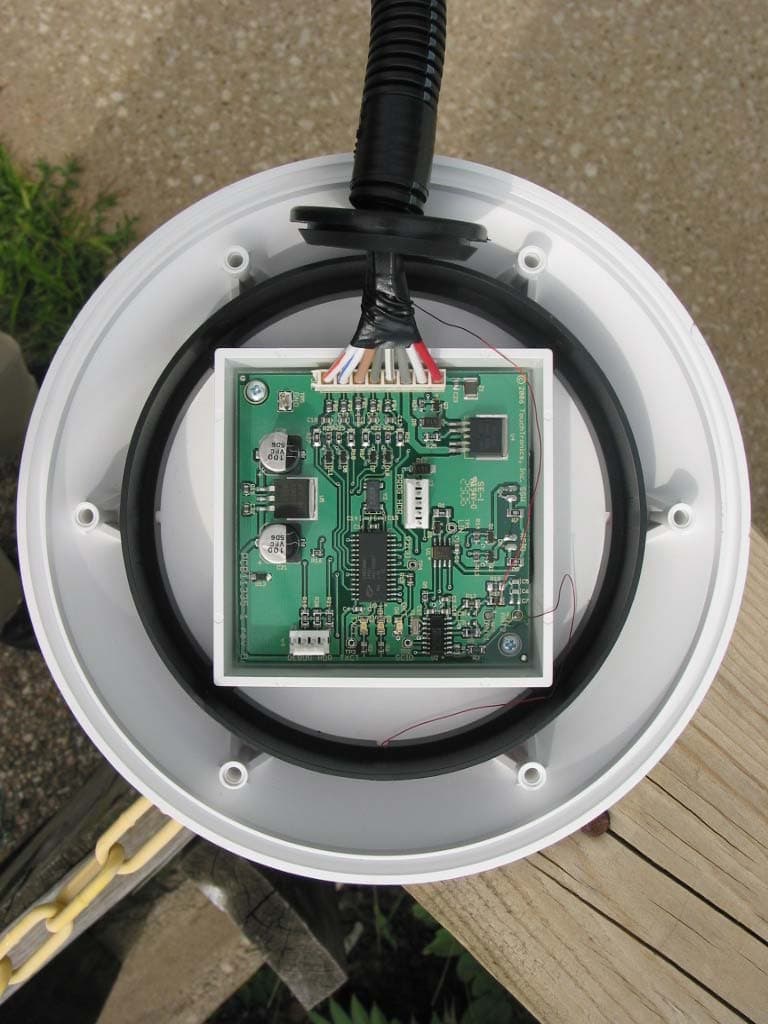
IVSM110
Sep 12, 2006Keyless Entry RFID Reader
Equipment Class
DCD - Part 15 Low Power Transmitter Below 1705 kHz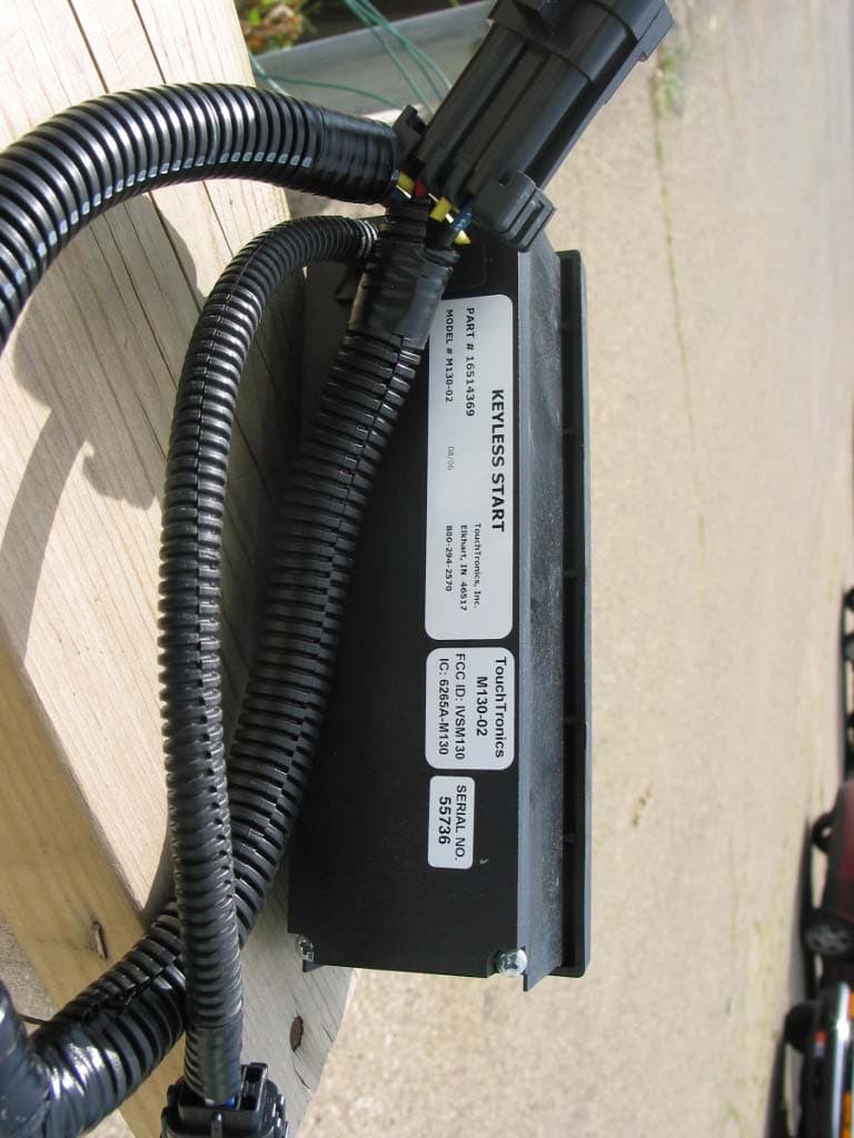
IVSM130
Sep 12, 2006Keyless Start RFID Reader
Equipment Class
DCD - Part 15 Low Power Transmitter Below 1705 kHz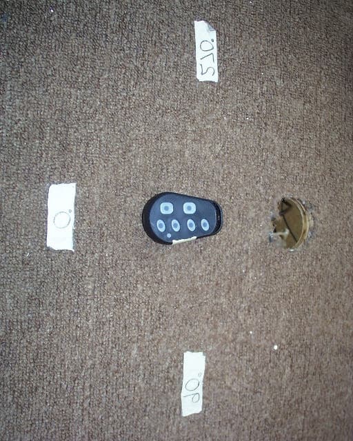
IVS1000TF
Mar 20, 2006Security/Remote Control Transmitter
Equipment Class
DSC - Part 15 Security/Remote Control Transmitter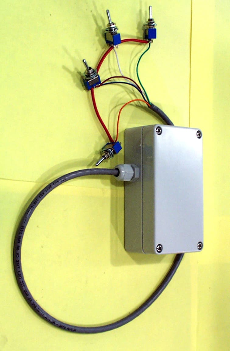
IVS1800TIMTW
Feb 12, 2006Security/Remote Control Transmitter
Equipment Class
DSC - Part 15 Security/Remote Control Transmitter