IVSM130Keyless Start RFID Reader
Touchtronics Inc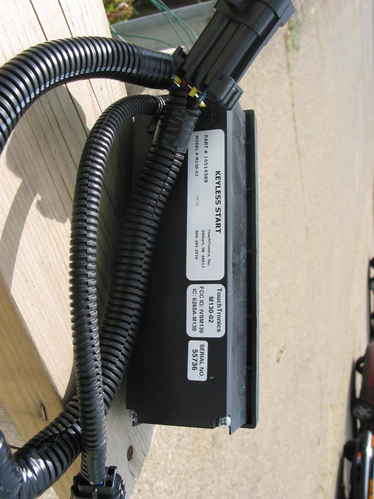
Click to zoom
Application Details
- Equipment Class
- DCD - Part 15 Low Power Transmitter Below 1705 kHz
- Date of Grant
- Sep 12, 2006
- Application Purpose
- Original Equipment
- Date of Application
- Sep 12, 2006
- Equipment Note
- Keyless Start RFID Reader
- Frequency Range
- 0.12320000 - 0.13420000
- Company
- Touchtronics Inc
- Country
- United States
Documents & Files
Document Text
Text extracted from the exhibit documents filed with the FCC. Open a document above to read the original.
Users Manual
O O P P E E R R A A T T I I N N G G I I N N S S T T R R U U C C T T I I O O N N S S K K E E Y Y L L E E S S S S E E N N T T R R Y Y / / S S T T A A R R T T / / S S E E C C U U R R I I T T Y Y S S Y Y S S T T E E M M KEYLESS TRUCK ENTRY - WRISTBAND KEY Swipe the area 4”-6” in f ront of the antenna using the a uthorized Wristband Key. The d oor will unlock for 6-seconds. While the door is unlocked, open the door and enter the truck. Antennas are located near each door. The door will unlock for 6-seconds. If the door is open longer than 6-seconds, the door will auto-lock when the door is closed. 1 ANTENNA STATUS LEDs a. There is a red and a green status LED installed on each antenna. b.The red LED will flash once anytime the unlock switch is pressed. c. The red LED will flash twice anytime an authorized Wristband Key is presented to the antenna. d. The green LED will turn on solid anytime the door is unlocked (6-seconds). e.The red LED will flash more than twice if there is a system failure (no data communication) between the Master curb side antenna and any of the other antennnas. 3 K EYLESS TRUCK EXIT - UNLOCK SWITCH Press the unlock switch and the corresponding door will unlock for 6-seconds. While the door is unlocked, open the door and exit the truck. There is one unlock switch for each door. The curb side and driver Unlock switches are located on the dash, the bulkhead and rear door u nlock switches are installed inside the cargo compartment near it’s door. 2 MANUAL TRUCK ENTRY & EXIT a.Only the rear door has a manual key to unlock the truck cargo compartment and gain entry to the truck. The cab can then be entered through the bulkhead door using the Unlock switch or the manual lever inside the door latch. Note: If the manual key is used for entry the security alarm will need to be deactivated within 5 seconds by presenting a valid Wristband Key to any antenna. See Cargo Compartment Security Section 6. b. All of the doors can be unlocked manually from inside the truck. 4 Side Door Bulkhead Rear Door CARGO COMPARTMENT SECURITY a. Anytime both the bulkhead and rear doors are closed and locked, and the ignition is OFF, the cargo compartment security zone is armed. b. The cargo compartment security zone is disarmed anytime an authorized W ristband Key is presented to the bulkhead or rear door antenna. c. If the driver remains inside the cargo comp artment and closes both bulkhead and rear doors, the cargo comp artment security zone will allow the driver to exit the cargo area by pressing either Unlock switch, located at the Bulkheard or Rear Door . d. The cargo compartment zone alarm triggers when either the bulkhead or rear door is opened manually and NO Valid Wristband Key is presented to any antenna within 5-seconds. 5 CAB & CARGO DOME LAMPS a. The cab and cargo dome lamps are automatically turned on for 60-seconds when any door is opened. b. The cab and cargo dome lamps are automatically turned on for 10-seconds when any door is opened and the ignition is on. c. The cab and cargo dome lamps if turned on automatically will turn of f any time the truck is st arted. d. The cab and cargo dome lamps will turn on maually anytime the Dome Light Dash Switch is pressed and will ONLY turn off if the Dome Light Switch is pressed again. 6 POWER REDUCTION MODE a. The system enters the Power Reduction Mode, commonly called the Sleep Mode, anytime no activity is detected for 30-minutes. b. The system exits the Power Reduction Mode anytime a valid Wristband Key is presented, an Unlock switch is pressed or the alarm is triggered. 7 ARMING AND DISARMING THE SECURITY SYSTEM Arming the Security System a. Truck is armed anytime all doors are closed. b. Cargo compartment is armed anytime BOTH doors are closed. Disarming the Security System a. Wristband Key is presented to any Antenna or the Keyless Start unit and doors are closed. b. Pressing any Unlock switch just prior to opening the corresponding door. Alarm T riggered a. If the alarm is triggered, the siren will sound and the dome light s will flash. b. The Doors Ajar LED will flash until the Keyless Start detects a valid Wristband Key. Disarming the Security System if the Alarm is Triggered a. Wristband Key is presented to any door or the Keyless Start unit. b. Truck ignition is on. c. Master Key is presented to any Antenna or the Keyless Start unit. 57315 Nagy DriveW arranty Elkhart, IN 46517& Fax: 574-293-1611Technical Support www.touchtronics.com574-294-2570 T O U C H T R O N I C S, I N C. v v 10 KEYLESS START STATUS LEDs a. The red Doors Ajar LED will turn on solid anytime the driv- er, bulkhead or rear doors are open and the truck is off. The red Doors Ajar LED will flash if the alarm has been triggered. b. The green Run LED will be on solid anytime the truck is running. The green Run LED will flash when a valid Wristband Key is authorized until the Engine Start button is pressed or will timeout at 25 seconds. c. The yellow Start LED will be on solid when Engine Start button is pressed and the engine can be started. The yellow Start LED will flash if the Engine Start button is pressed and the engine can’t be started due to a failed door switch or antenna connector. d. The red CK SYS LED will flash twice anytime a valid Wristband Key is presented. The red CK SYS LED will flash continuously during start-up mode if there is a system failure at any antenna. If the truck enters sleep mode, the CK SYS LED will flash at 5-second ratio until truck exits sleep mode. KEYLESS STARTING & STOPPING a. Close the driver, bulkhead and rear doors. b. Swipe the authorized Wristband Key across the target area on the left side of the Keyless Start unit. c. The red CK SYS LED will flash twice, which indicates a valid Wristband Key has been received and the Keyless Start unit will turn on. The green Run LED will flash for 25 seconds indicating the truck is ready to be started and the switch backlights will also be on. d. Check the Doors Ajar LED on the Keyless Start un…
Text truncated - open the document above for the full version.
Test Report
Engineering Test Report No. 37012-01 Measurement of RF Interference from a Model M130 Transmitter For : Touchtronics, Inc. Elkhart, IN P.O. No. : 8532 Date Received : August 3, 2006 Date Tested : August 3, 2006 Test Personnel : Daniel E. Crowder Specification : FCC "Code of Federal Regulations” Title 47 Part 15, Subpart C Test Report By : Daniel E. Crowder Approved By : Raymond J. Klouda Registered Professional Engineer of Illinois - 44894 Elite Electronic Engineering Inc. 1516 Centre Circle Downers Grove, IL 60515 Tel : (630) 495-9770 Fax: (630) 495-9785 www.elitetest.com Engineering Test Report No. 37012-01 THIS REPORT SHALL NOT BE REPRODUCED, EXCEPT IN FULL, WITHOUT THE WRITTEN APPROVAL OF ELITE ELECTRONIC ENGINEERING INC. Page 2 of 11 TABLE OF CONTENTS PARAGRAPH DESCRIPTION OF CONTENTS PAGE NO. 1.0 INTRODUCTION ................................................................................................................................................ 3 1.1 Description of Test Item.................................................................................................................................... 3 1.2 Purpose ............................................................................................................................................................. 3 1.3 Deviations, Additions and Exclusions ............................................................................................................... 3 1.4 Applicable Documents -.................................................................................................................................... 3 1.5 Subcontractor Identification .............................................................................................................................. 3 1.6 Laboratory Conditions..................................................................................................................................... 3 2.0 TEST ITEM SETUP AND OPERATION............................................................................................................. 3 2.1 Power Input...................................................................................................................................................... 3 2.2 Grounding......................................................................................................................................................... 3 2.3 Support Equipment........................................................................................................................................... 4 2.4 Interconnect Cables........................................................................................................................................... 4 2.5 Operational Mode ............................................................................................................................................. 4 3.0 TEST EQUIPMENT............................................................................................................................................. 4 3.1 Test Equipment List .......................................................................................................................................... 4 3.2 Calibration Traceability ................................................................................................................................... 4 4.0 REQUIREMENTS, PROCEDURES AND RESULTS.......................................................................................... 4 4.1 Powerline Conducted Emissions ..................................................................................................................... 4 4.1.1 Requirements............................................................................................................................................ 4 4.2 Radiated Emissions.......................................................................................................................................... 4 4.2.1 Requirements............................................................................................................................................ 4 4.2.2 Procedures .................................................................................................................................................... 5 4.2.2.1 Preliminary Radiated Measurements ............................................................................................... 5 4.2.2.2 Final Radiated Measurements ........................................................................................................... 5 4.2.3 Results ...................................................................................................................................................... 5 5.0 CONCLUSIONS................................................................................................................................................... 5 6.0 CERTIFICATION ................................................................................................................................................ 6 7.0 ENDORSEMENT DISCLAIMER........................................................................................................................ 6 TABLE I - EQUIPMENT LIST ................................................................................................................................ 7 Engineering Test Report No. 37012-01 Page 3 of 11 Measurement of RF Emissions from the M130 transmitter 1.0 INTRODUCTION: 1.1 Description of Test Item - This document represents the results of the series of radio interference measurements performed on a model M130 transmitter, (hereinafter referred to as the test item). The test item was designed to transmit at approximately 135 kHz using an internal antenna. The test item was manufactured and submitted for testing by Touchtronics, Inc. located in Elkhart, IN. 1.2 Purpose - The test series was performed…
Text truncated - open the document above for the full version.
Test Setup Photos
Radiated Emissions Worst Case Horizontal Polarization Radiated Emissions Worst Case Vertical Polarization
Contact Information
Applicant
David W Evans(Senior Design Engineer)
Test Firm
Elite Electronic Engineering Co.Daniel Crowder
Technical Specifications
| # | Rule Parts | Frequency Range | Power Output |
|---|---|---|---|
| 1 | 15C | 0.1232 MHz - 0.1342 MHz | - |
Other Applications from Touchtronics Inc
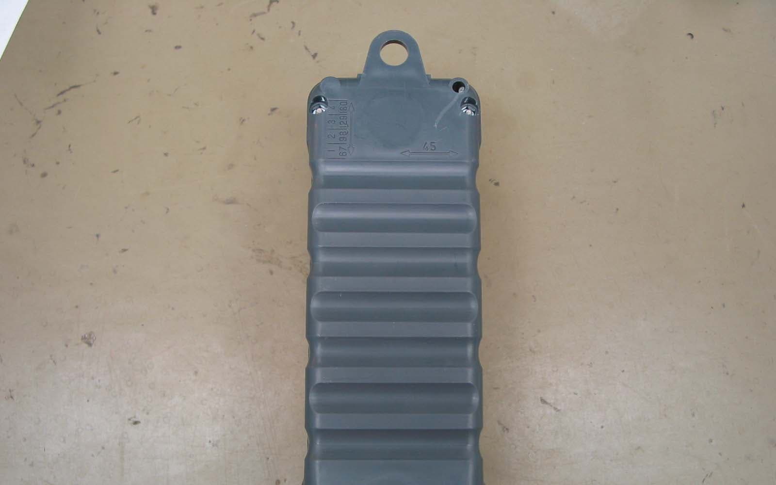
IVS1000TR
Apr 20, 2010Remote Control Transmitter
Equipment Class
DSC - Part 15 Security/Remote Control Transmitter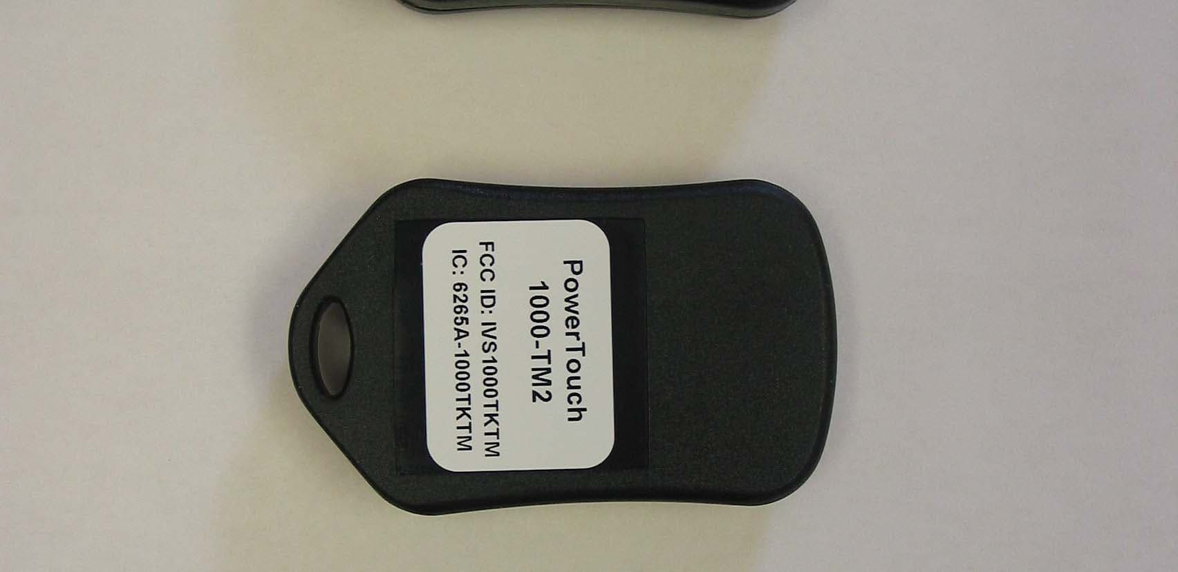
IVS1000TKTM
Mar 24, 2008Security/Remote Control Transmitter
Equipment Class
DSC - Part 15 Security/Remote Control Transmitter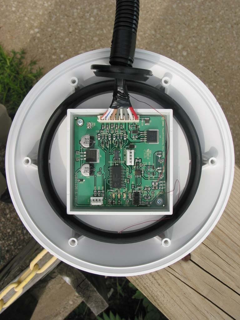
IVSM110
Sep 12, 2006Keyless Entry RFID Reader
Equipment Class
DCD - Part 15 Low Power Transmitter Below 1705 kHz
IVS1000TF
Mar 20, 2006Security/Remote Control Transmitter
Equipment Class
DSC - Part 15 Security/Remote Control Transmitter
IVS1800TIMTW
Feb 12, 2006Security/Remote Control Transmitter
Equipment Class
DSC - Part 15 Security/Remote Control Transmitter