IWD4881048810A & 48810B REPEATERS
Radio Frequency Systems Inc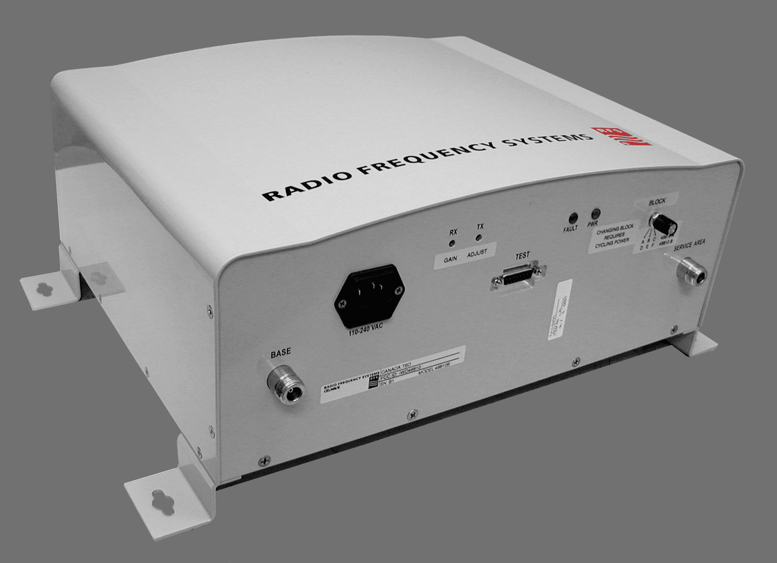
Click to zoom
Application Details
- Equipment Class
- AMP - Amplifier
- Date of Grant
- Jan 31, 2002
- Application Purpose
- Original Equipment
- Date of Application
- Dec 20, 2001
- Equipment Note
- 48810A & 48810B REPEATERS
- Frequency Range
- 1930.00000000 - 1990.00000000
- Company
- Radio Frequency Systems Inc
- Country
- United States
Documents & Files
Document Text
Text extracted from the exhibit documents filed with the FCC. Open a document above to read the original.
Users Manual
48810A & 48810B User's Manual 200 Pondview Drive, Meriden, CT 06450 • (877) 737-9675 • Fax (203) 821-3852 www.rfsworld.com Disclaimer All information and statements contained herein are accurate to the best of the knowledge of Radio Frequency Systems, but Radio Frequency Systems does not make any warranty with respect thereto, including without limitation any results, which may be obtained from the products described herein or the infringement by such products of any proprietary rights of any persons. Use or application of such information or statements is at the user’s sole risk, without any liability on the part of Radio Frequency Systems. Nothing herein shall be construed as license of or recommendation for use, which infringes upon any proprietary rights of any person. Product material and specifications are subject to change without notice. All sales of the products described herein are subject to Radio Frequency System's standard terms of sale and the specific terms of any particular sale. Table of Contents General Statements 1 Maximum Permissible Exposure Limits 2 Product Overview 3 Field Tune-up, Alignment or Calibration 3 FCC ID and Canada Certification Numbers 3 Theory of Operation 3 Electrical Specifications 4 Mechanical Specifications 4 Environmental Specifications 4 Intermodulation, Power, and AGC 4 AGC Automatic Shutdown 5 Manual Gain Adjustment 5 AC/DC Power 6 Grounding and Surge Protection 6 Antenna Isolation 6 Installation 7 Diagnostics/Troubleshooting 8 Test Points 9 Component Location 11 Maintenance, Repair and Warranty 12 Periodic Maintenance 12 Ordering and Returning Components 12 General Statements Thank you for selecting this RFS product. We are confident that you will find this product in proper working order, meeting all stated specifications. If not, please contact customer service immediately at 1-800-321-4700 and we will resolve the issue without hesitation. Please read this manual. A full understanding of product operation will support optimal performance and prevent accidental damage not covered by the stated warranty. Do not operate this product without proper loads on both antenna ports. You must connect both antenna ports to an antenna or a 50-Ohm load, rated for at least 1 watt. These products receive and amplify RF signals in the 1900 MHz PCS band. As such, these products are intended for use by the licensee of the respective service and should not be used without the expressed permission of the licensee. The 48810 PCS Band Repeater can be used to cover indoor or outdoor areas. It is designed and optimized for low cost, high reliability, and ease of use. This manual provides information on the proper operation and care of the repeater, however, Radio Frequency Systems can provide the total package of components and hardware for any type of repeater installation. See our catalog for the full line of antennas, coaxial cables, and accessories at www.rfsamericas.com . For assistance with this repeater installation and/or design of the distribution network to get the best coverage possible contact RFS Applications Engineering at 1-800-659-1880 48810 Ground Kit Wall/ Roof Feedthru 1/2" or 7/8" Coaxial cable Distribution Network Surge Arrestor Jumpers BaseService Radiaflex 1/2" Plenum Riser Rated Coax 1/2 or 7/8" Cable Taps 1/2" Plenum Coax Donor Antenna Hangers and Standoffs In-building Antennas In-band or Cross-band Combiners 2, 3, or 4 Way Splitters 1 Maximum Permissible Exposure Limits THIS PRODUCT IS CATEGORICALLY EXCLUDED FROM ROUTINE ENVIRONMENTAL EVALUATION ACCORDING TO CFR 47, SECTION 1.1037 AND 2.1091. Repeaters like the 48810 generate radio signals and thereby give rise to electromagnetic fields. The installer is expected to have a complete understanding of CFR Title 47, Sections 1.1307, 1.1310 and 2.1091. A brief discussion follows but is not intended to be a substitute. Additional information can also be obtained from OET Bulletin 65. Antenna installation should be performed by qualified technicians only. Installation instructions are not optional and are for the purpose of satisfying FCC RF Exposure Compliance. All antennas (donor and service) are to be fixed-mounted and physically secured to one location. Maximum donor antenna gain is 28 dB. Maximum service area antenna gain is 10 dB. There are two types of antennas attached to this unit. Installation considerations for both of these will be discussed separately. Donor antennas receive the base site TX signals and transmit the mobile TX signals back to the base site (uplink paths). These are typically mounted on rooftops or tower structures in occupational / controlled esposure areas. The maximum composite power of the uplink path is +15 dBm (32 mW). Section 1.307(b)(1) excludes from routine environmental evaluation, facilities, operations and transmitters that, according to Table 1 (titled "Cellular Radiotelephone Service"), are less than 1000W ERP for building mounted antennas and less than 1000W and greater than 10 meters above ground for non building-mounted antennas. As such, with maximum power from the uplink path @ +15 dBm (32 mW) and a maximum antenna gain of 28 dB, the donor antenna installation will not exceed 20 Watts (+43 dBm) and is categorically excluded. However, according to Section 1.1307 (b)(1), the appropriate exposure limits of 1.1310 are applicable to all facilities, operations, and transmitters. Therefore, the MPE (Maximum Permissible Exposure) of Section 1.1310 applies to the donor antenna installation. OET Bulletin 65 provides methods of calculating power density based upon the ERP and distance. It would be impossible to cover every possible configuration in this manual. Likewise, it would be unreasonable to dictate the exact parameters of every installation; therefore, it is the responsibility of the qualified technician to know and ensure that Sections 1.1307 and 1.1310 of CFR Title 47 are being met. Service antennas are also fixed mounted and covered by t…
Text truncated - open the document above for the full version.
Block Diagram
Duplexers Service Base Power Amplifier LNA Converter Power Amplifier LNA Converter Rx or Uplink Tx or Downlink Control Board Test Manual Gain HF Filter HF Filter Power and Fault LEDs Band Select Block Diagram 48810
ID Label/Location Info
I W D 488 10
Test Report
Master: FCC-PR24-E Date: July 24, 2001 Test Report:1W04499 Applicant:Radio Frequency Systems 4100 SW Research Way Corvallis, OR 97333 USA Equipment Under Test:48810A & 48810B (EUT)PCS Band Signal Booster FCC ID:1WD48810 In Accordance With:FCC Part 24, Subpart E Tested By:Nemko Canada Inc. 3325 River Road, R.R. 5 Ottawa, Ontario K1V 1H2 Authorized By: R. Grant, Wireless Group Manager Date: Total Number of Pages:111 Nemko Canada Inc. FCC PART 24, SUBPART E PROJECT NO.: 1W04499 EQUIPMENT: 48810A & 48810B FCC ID: IWD48810 Page 2 of 111 Table of Contents Section 1. Summary of Test Results.......................................................................................... 3 Section 2. General Equipment Specification ........................................................................... 5 Section 3. RF Power Output .....................................................................................................6 Section 4. Occupied Bandwidth.............................................................................................. 19 Section 5. Spurious Emissions at Antenna Terminals........................................................... 62 Section 6. Field Strength of Spurious................................................................................... 105 Section 7. Frequency Stability.............................................................................................. 107 Section 8. Block Diagrams..................................................................................................... 108 Section 9. Test Equipment List ............................................................................................. 111 Nemko Canada Inc. FCC PART 24, SUBPART E PROJECT NO.: 1W04499 EQUIPMENT: 48810A & 48810B FCC ID: IWD48810 Page 3 of 111 Section 1.Summary of Test Results General All measurements are traceable to national standards. These tests were conducted on a sample of the equipment for the purpose of demonstrating compliance with FCC Part 24, Subpart E. THIS TEST REPORT RELATES ONLY TO THE ITEM(S) TESTED. THE FOLLOWING DEVIATIONS FROM, ADDITIONS TO, OR EXCLUSIONS FROM THE TEST SPECIFICATIONS HAVE BEEN MADE. See “ Summary of Test Data”. TESTED BY: Glen Westwell, Wireless TechnologistDATE: December 20, 2001 Nemko Canada Inc., a testing laboratory, is accredited by the Standards Council of Canada. The tests included in this report are within the scope of this accreditation. The results apply only to the samples tested. Nemko Canada Inc. authorizes the above named company to reproduce this report provided it is reproduced in its entirety and for use by the company’s employees only. Any us e whic h a third p a rty ma k e s o f this re p o rt, o r a ny re lia nc e o n o r d e c is io ns to b e ma d e b a s e d o n it, a re the re s p o ns ib ility of such third parties. Nemko Canada Inc. accepts no responsibility fo r d a ma ge s , if a ny, s uffe re d b y a ny third p a rty a s a re s ult o f d e c is io ns ma d e o r a c tio ns b a s e d o n this re p o rt. This report applies only to the items tested. Nemko Canada Inc. FCC PART 24, SUBPART E PROJECT NO.: 1W04499 EQUIPMENT: 48810A & 48810B FCC ID: IWD48810 Page 4 of 111 Summary Of Test Data Name Of TestPara. No.Result RF Power Output2.1046Complies Occupied Bandwidth2.1049Complies Spurious Emissions at Antenna Terminals2.1051Complies Field Strength of Spurious Emissions2.1053Complies Frequency Stability2.1055Complies Test Conditions: IndoorTemperature: 23 °C Humidity:37 % OutdoorTemperature: 3 °C Humidity:48 % Nemko Canada Inc. FCC PART 24, SUBPART E PROJECT NO.: 1W04499 EQUIPMENT: 48810A & 48810B FCC ID: IWD48810 Page 5 of 111 Section 2.General Equipment Specification Manufacturer:Radio Frequency Systems Model No.:48810A & 48810B Serial No.:A1 & B1 Date Received In Laboratory:December 5, 2001 Nemko Identification No.:Item #1 & 2 Supplementary Voltage:120 VAC Frequency Range:48810ADownlink:1930-1945MHz (BLK A) 1950-1965MHz (BLK B) 1975-1990MHz (BLK C) Uplink:1850-1865MHz (BLK A) 1870-1885MHz (BLK B) 1895-1910MHz (BLK C) 48810BDownlink:1945-1950MHz (BLK D) 1965-1970MHz (BLK E) 1970-1975MHz (BLK F) Uplink:1865-1870MHz (BLK D) 1885-1890MHz (BLK E) 1890-1895MHz (BLK F) Output Impedance:50 ohms RF Output (Rated):15dBm (31.6 mW) Emission Designator:F9W, DXW, GXW Nemko Canada Inc. FCC PART 24, SUBPART E PROJECT NO.: 1W04499 EQUIPMENT: 48810A & 48810B FCC ID: IWD48810 Page 6 of 111 Section 3.RF Power Output Para. No.: 2.1046 Test Performed By: Glen WestwellDate of Test: December 17, 2001 Minimum Standard:Para. No.: 24.232. Test Results:Complies. Measurement Data:See attached graphs. The maximum RF Output Power is within +/- 1 dB of the manufacturers’ rating. The RF Output Power is de-rated according to the number of channels via AGC and is equal to P MAX – 10Log N. P MAX = Maximum RF Output Power N = Number of Channels Nemko Canada Inc. FCC PART 24, SUBPART E PROJECT NO.: 1W04499 EQUIPMENT: 48810A & 48810B FCC ID: IWD48810 Page 7 of 111 Nemko Canada Inc. FCC PART 24, SUBPART E PROJECT NO.: 1W04499 EQUIPMENT: 48810A & 48810B FCC ID: IWD48810 Page 8 of 111 Nemko Canada Inc. FCC PART 24, SUBPART E PROJECT NO.: 1W04499 EQUIPMENT: 48810A & 48810B FCC ID: IWD48810 Page 9 of 111 Nemko Canada Inc. FCC PART 24, SUBPART E PROJECT NO.: 1W04499 EQUIPMENT: 48810A & 48810B FCC ID: IWD48810 Page 10 of 111 Nemko Canada Inc. FCC PART 24, SUBPART E PROJECT NO.: 1W04499 EQUIPMENT: 48810A & 48810B FCC ID: IWD48810 Page 11 of 111 Nemko Canada Inc. FCC PART 24, SUBPART E PROJECT NO.: 1W04499 EQUIPMENT: 48810A & 48810B FCC ID: IWD48810 Page 12 of 111 Nemko Canada Inc. FCC PART 24, SUBPART E PROJECT NO.: 1W04499 EQUIPMENT: 48810A & 48810B FCC ID: IWD48810 Page 13 of 111 Nemko Canada Inc. FCC PART 24, SUBPART E PROJECT NO.: 1W04499 EQUIPMENT: 48810A & 48810B FCC ID: IWD48810 Page 14 of 111 Nemko Canada Inc. FCC PART 24, SUBPART E PROJECT NO.: 1W04499 EQUIPMENT: 48810A & 48810B FCC ID: IWD48810 Page 15 of 111 Nemko Canada Inc. FCC …
Text truncated - open the document above for the full version.
Test Report
Frequency Stability Test Results:Complies. The maximum frequency drift is _0_ Hz. Measurement Data:Standard Test Voltage:STV: 120Vac Standard Test Freq.:STF: 1958MHz , 1878MHz STF: 1968MHz , 1888MHz Test ConditionFrequency (kHz)Frequency Drift (kHz) STV1958000, 1878000 1968000, 1888000 0 0 115% STV“0 85% STV“0 -30 °C “0 -20 °C “0 -10 °C “0 0 °C “0 +10 °C “0 +30 °C “0 +40 °C “0 +50 °C “0
Contact Information
Applicant
Paul Carney(Senior RF Engineer)
Technical Contact
NEMKO CANADA INC.RUBY DULMAGE
[email protected]800-563-6336
3325 RIVER ROAD · OTTAWA, ONTARIO · Canada
Non-Technical Contact
NEMKO CANADA INC.RUBY DULMAGE
[email protected]800-563-6336
Test Firm
Nemko Canada Inc.Stuart Beck
Technical Specifications
| # | Rule Parts | Frequency Range | Power Output | Emission |
|---|---|---|---|---|
| 6 | 24E | 1.93 GHz - 1.99 GHz | 32.00 mW | DXW |
Other Applications from Radio Frequency Systems Inc

IWD-W3900008
Feb 08, 2010PCS 1900 Pico-repeater
Equipment Class
PCB - PCS Licensed Transmitter
IWD-W3900006
Feb 08, 2010CDMA/CELL 850 Pico-repeater
Equipment Class
TNB - Licensed Non-Broadcast Station Transmitter
IWD-W3900005
Feb 08, 2010iDEN 800 Pico-repeater
Equipment Class
TNB - Licensed Non-Broadcast Station Transmitter
IWD-W3900007
Feb 08, 2010iDEN 900 Pico-repeater
Equipment Class
PCB - PCS Licensed Transmitter
IWD-W3900009
Feb 08, 2010PCS 1900 Pico-repeater
Equipment Class
PCB - PCS Licensed Transmitter