IWD4890048910, 48920 and 48930 Bi-directional amplifiers
Radio Frequency Systems Inc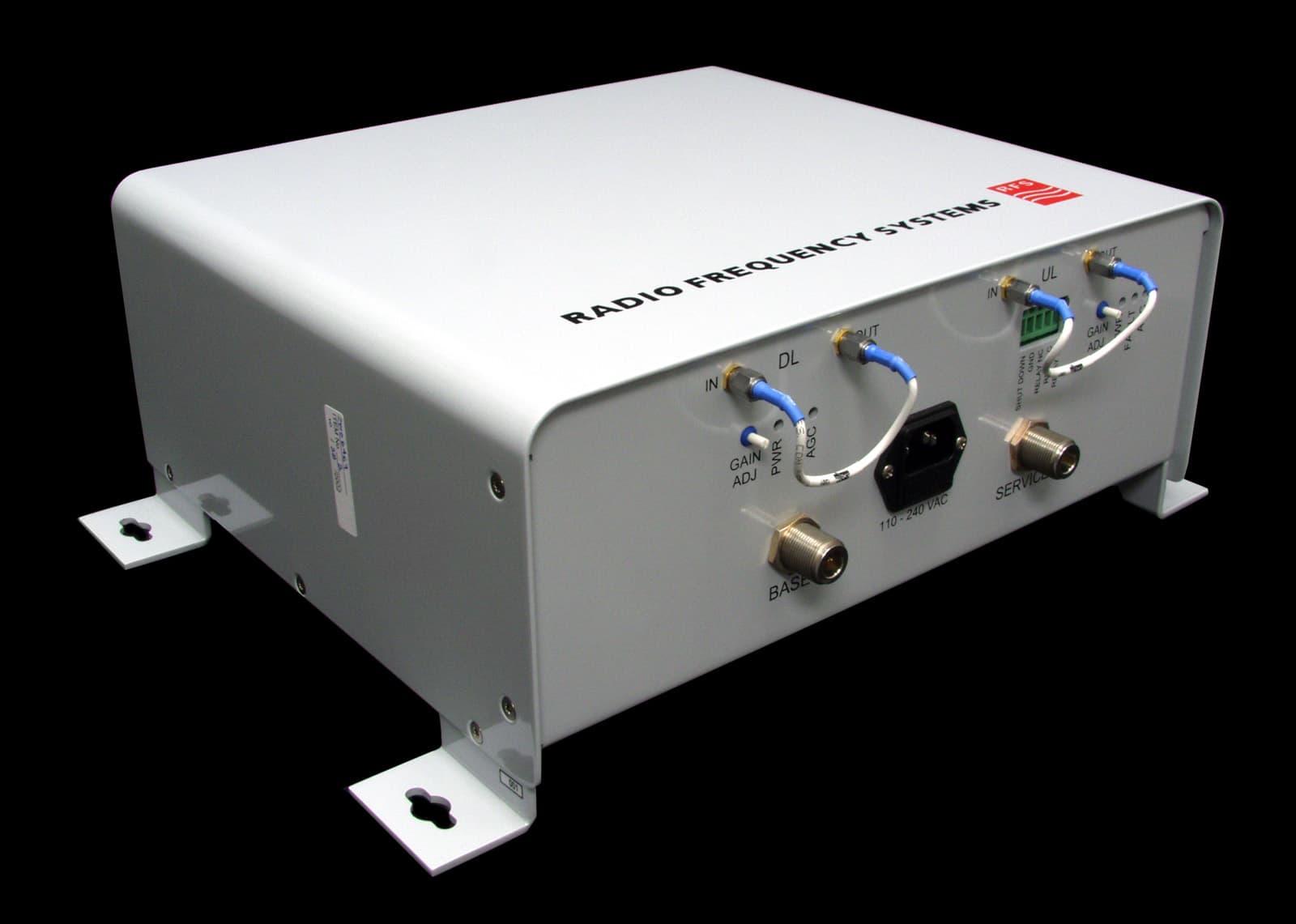
Click to zoom
Application Details
- Equipment Class
- AMP - Amplifier
- Date of Grant
- Feb 13, 2003
- Application Purpose
- Original Equipment
- Date of Application
- Dec 02, 2002
- Equipment Note
- 48910, 48920 and 48930 Bi-directional amplifiers
- Frequency Range
- 869.00000000 - 894.00000000
- Company
- Radio Frequency Systems Inc
- Country
- United States
Documents & Files
Document Text
Text extracted from the exhibit documents filed with the FCC. Open a document above to read the original.
Users Manual
48910, 920, 930 User's Manual 200 Pondview Drive, Meriden, CT 06450 • (877) 737-9675 • Fax (203) 821-3852 www.rfsworld.com 22 Disclaimer All information and statements contained herein are accurate to the best of the knowledge of Radio Frequency Systems, but Radio Frequency Systems does not make any warranty with respect thereto, including without limitation any results, which may be obtained from the products described herein or the infringement by such products of any proprietary rights of any persons. Use or application of such information or statements is at the user’s sole risk, without any liability on the part of Radio Frequency Systems. Nothing herein shall be construed as license of or recommendation for use, which infringes upon any proprietary rights of any person. Product material and specifications are subject to change without notice. All sales of the products described herein are subject to Radio Frequency System's standard terms of sale and the specific terms of any particular sale. 33 TABLE OF CONTENTS GENERAL STATEMENTS..................................................................................................................................4 MAXIMUM PERMISSIBLE EXPOSURE LIMITS........................................................................5 PRODUCT OVERVIEW...........................................................................................................................................6 FIELD TUNE-UP, ALIGNMENT OR CALIBRATION...........................................................................................................6 FCC ID AND CANADA CERTIFICATION NUMBERS......................................................................................................6 THEORY OF OPERATION........................................................................................................................................................7 ELECTRICAL SPECIFICATIONS.............................................................................................................................................8 MECHANICAL SPECIFICATIONS...........................................................................................................................................8 ENVIRONMENTAL SPECIFICATIONS...................................................................................................................................8 INTERMODULATION, POWER, AND AGC.........................................................................................................................9 AGC AUTOMATIC SHUTDOWN..........................................................................................................................................10 MANUAL GAIN ADJUSTMENT.............................................................................................................................................10 AC/DC POWER.......................................................................................................................................................................10 GROUNDING AND SURGE PROTECTION........................................................................................................................10 EXTERNAL FILTER PORTS..................................................................................................................................................11 INSTALLATION.............................................................................................................................................................11 ANTENNA ISOLATION.............................................................................................................................................................13 DIAGNOSTICS/TROUBLESHOOTING..............................................................................................13 TEST POINT DESCRIPTIONS..............................................................................................................................................................13 FACEPLATE...............................................................................................................................................................................13 COMPONENT LOCATION................................................................................................................................14 MAINTENANCE, REPAIR AND WARRANTY............................................................................15 44 General Statements Thank you for selecting this RFS product. We are confident that you will find this product in proper working order, meeting all stated specifications. If not, please contact customer service immediately at 1-800-321-4700 and we will resolve the issue without hesitation. Please read this manual. A full understanding of product operation will support optimal performance and prevent accidental damage not covered by the stated warranty. ß Do not operate this product without proper loads on both antenna ports. You must connect both antenna ports to an antenna or a 50-Ohm load, rated for at least 1 watt. ß These products receive and amplify RF signals. As such, these products are intended for use by the licensee of the respective service and should not be used without the expressed permission of the licensee. ß Do not remove the cover for service. There are no internal adjustments. Path manual gain adjustment access holes are clearly marked on the bottom. Under normal circumstances, you need not make any adjustments. For more information, see installation section. ß The terminology “RX” and “TX” are being replaced by “UL” for uplink and “DL” for downlink respectively. The 48900 series bi-directional amplifiers/ repeaters/signal boosters are designed and optimized for low cost, high reliability, and ease of use. This manual provides information on the proper operation and care; however, Radio Frequency Systems can provide the total package of components and ha…
Text truncated - open the document above for the full version.
ID Label/Location Info
IWD48900 IC: 1634B-48900
Operational Description
Operational Description: IWD48900 The 48900 signal boosters are designed to enhance radio communication in buildings, basements, tunnels and other RF shielded environments. The 48910 is tuned for the 800 MHz Cellular band, the 48920 for the 800 SMR band and the 48930 for the 900 MHz SMR band. These units work by receiving and amplifying the base TX signals via a donor antenna directed at the desired base site. This RF path is called the downlink. The amplified base TX signal is re-radiated via antenna(s) or radiating cable into the Service Area. Subscriber mobile RF signals are received by the same service area radiating elements and amplified in the uplink RF path to be radiated back to the base via the donor antenna. Ground Kit Donor Antenna The LNAs and Power Amplifiers are broadband. The same amplifiers are used for the uplink and downlink. Likewise, the control board is the same for both models. Differentiation is provided by the duplexing filters on the base and service area connectors that determine the basic passband and direct the RF signals to the proper gain path, uplink and downlink respectively. Both the downlink and uplink have Automatic Gain Control (AGC) in the power amplifiers to prevent an overdrive condition. Manual gain adjustment is provided in the LNA stage. Overdrive limiting is provided by the AGC circuitry and set at the factory. This ensures that the unit will not exceed FCC limits for spurious emissions. The control board distributes DC power to the amplifier modules and monitors each module for any fault conditions. LED indicators provide visual diagnostics and a NC / NO relay provides for remote notification for any fault condition. SMA female connectors on the faceplate of the 48900 allow for connection of externally mounted passive 50 Ohm filtering. The external filter can only limit the related passband to a narrower pass band within the approved service. This is helpful if there are strong undesired signals in the pathway of the donor antenna. Should the conditions change in the field, the external filter can be removed or replaced with minimal interruption in service. Separate ports are provided for both the uplink and downlink.
RF Exposure Info
RF SAFETY EXHIBIT AND CALIBRATION STATEMENT IWD48900 EXCERPT FROM MANUAL Maximum Permissible Exposure Limits THIS PRODUCT IS CATEGORICALLY EXCLUDED FROM ROUTINE ENVIRONMENTAL EVALUATION ACCORDING TO CFR 47, SECTION 1.1037. Repeaters like the 48900 series generate radio signals and thereby give rise to electromagnetic fields. The installer is expected to have a complete understanding of CFR Title 47, Sections 1.1307 and 1.1310. A brief discussion follows but is not intended to be a substitute. Additional information can also be obtained from OET Bulletin 65. ß Antenna installation should be performed by qualified technicians only. ß Installation instructions are not optional and are for the purpose of satisfying FCC RF Exposure Compliance. ß All antennas (donor and service) are to be fixed-mounted and physically secured to one location. ß Maximum donor antenna gain is 28 dB. ß Non building-mounted donor antennas must be greater than 10 meters above ground. ß Maximum service area antenna ERP is 1.0 Watt. ß Minimum separation to any body part of any person is 25cm. There are two types of antennas attached to this unit. The donor antenna is typically roof mounted and the service antenna is usually mounted in a publicly accessible area. Both antennas should be fixed mounted. Installation considerations for both of these will be discussed separately. Donor antennas receive the base site TX signals and transmit the mobile TX signals back to the base site (uplink paths). These are typically mounted on rooftops or tower structures. The maximum composite power of the uplink path is 160 mW (+22dBm). Section 1.307(b)(1) excludes from routine environmental evaluation, facilities, operations and transmitters that, according to Table 1 (titled "Cellular Radiotelephone Service"), are less than 1000W ERP for building mounted antennas and less than 1000W and greater than 10 meters above ground for non building-mounted antennas. As such, with maximum power from the uplink path @ 160 mW (+22dBm) and a maximum antenna gain of 28 dB, the donor antenna installation will not exceed 1000 Watts (+60 dBm) and is categorically excluded. However, according to Section 1.1307 (b)(1), the appropriate exposure limits of 1.1310 are applicable to all facilities, operations, and transmitters. Therefore, the MPE (Maximum Permissible Exposure) of Section 1.1310 applies to the donor antenna installation. OET Bulletin 65 provides methods of calculating power density based upon the ERP and distance. It would be impossible to cover every possible configuration in this manual. Likewise, it would be unreasonable to dictate the exact parameters of every installation; therefore, it is the responsibility of the qualified technician to know and ensure that Sections 1.1307 and 1.1310 of CFR Title 47 are being met. The following scenario is a typical rooftop installation in an uncontrolled area (worst-case) using a 18 dB gain donor antenna. The MPE @ 824 MHz is 0.549 mW per cm 2 . The uplink is being driven to its maximum output power (+22 dBm); the resultant ERP is +40 dBm or 10,000 mW. OET Bulletin 65 provides the following formula for calculating the power density with the EPA recommended factor for ground reflection: 1.05 ERP/ π R 2 Where R is the distance to center (of any body part of person). Solving for 10,000 mW @ 3ft. (91.44 cm) we get a power density of 0.4 mW per cm 2 . The Yagi antenna in this scenario must be mounted in such a way that no body part of any person may come closer than 3 feet in the direction of the main power beam. This will limit exposure to well within the MPE. Service antennas are also fixed mounted and covered by the same MPE considerations as the donor antenna. However, this assumes that the area is always general population/uncontrolled and that the minimum distance in most installations will be less than 3 feet. According to Table 1(B) of Section 1.1310, the power density @ 894 MHz is 0.596 mW/cm 2 . The maximum power of the 48900 downlink (base to service area) is +22 dBm (160 mW). Assuming no feeder cable loss and a service area antenna gain of 8 dB, a safe minimum separation of 10 inches (25 cm) is required to stay within the MPE. 1.05 x 1000 mW/3.14 x 252 = 1050/1962.5 =0.535 mW/cm 2 Therefore, the service area antenna should be mounted such that no body parts of any person may come closer than 10 inches (or 25 cm). The service area antenna gain is 8 dB in the example above, but may be increased to make up for cable and/or splitter or tap losses. For example, if a 2- way splitter is used to provide for two antennas in different parts of the service area, then the antenna gain may be increased to 11 dB to make up for the loss of the splitter 3.6 dB. The maximum service area antenna gain for any specific location can be calculated as follows: 8dB+ accumulated losses to the antenna. Field Tune-up, Alignment or Calibration There is no field tune-up or calibration necessary. These units are aligned and calibrated at the time of manufacture and are designed to retain calibration throughout the life of the product.
Test Report
Master: FCCPart22-90.doc Date: February 13, 2002 Test Report:2W06467 Applicant:Radio Frequency Systems 4100 SW Research Way Corvallis, OR 97333 USA Equipment Under Test:Bi-Directional Amplifiers, 48900 Series (EUT)48910, 48920 & 48930 FCC ID:IWD48900 In Accordance With:FCC Part 22 & FCC Part 90 Tested By:Nemko Canada Inc. 303 River Road, R.R. 5 Ottawa, Ontario K1V 1H2 Authorized By: Kevin Carr, EMC Specialist Date:27 November 2002 Total Number of Pages:50 Nemko Canada Inc.FCC PART 22 & FCC PART 90 PROJECT NO.:2W06467 EQUIPMENT: Bi-Directional Amplifiers, 48900 Series Page 2 of 50 Table of Contents Section 1. Summary of Test Results......................................................................................3 Section 2. General Equipment Specification........................................................................5 Section 3. RF Power Output..................................................................................................6 Section 4. Occupied Bandwidth..........................................................................................10 Section 5. Field Strength of Spurious Emissions................................................................45 Section 6.Block Diagrams....................................................................................................48 Section 7.Test Equipment List............................................................................................50 Nemko Canada Inc.FCC PART 22 & FCC PART 90 PROJECT NO.:2W06467 EQUIPMENT: Bi-Directional Amplifiers, 48900 Series Page 3 of 50 Section 1.Summary of Test Results General All measurements are traceable to national standards. These tests were conducted on a sample of the equipment for the purpose of demonstrating compliance with FCC Part 22 and FCC Part 90 for family listing. THIS TEST REPORT RELATES ONLY TO THE ITEM(S) TESTED. THE FOLLOWING DEVIATIONS FROM, ADDITIONS TO, OR EXCLUSIONS FROM THE TEST SPECIFICATIONS HAVE BEEN MADE. See “ Summary of Test Data”. TESTED BY: ______________________________DATE: 27 November 2002 Glen Westwell, Wireless Technologist Nemko Canada Inc. authorizes the above named company to reproduce this report provided it is reproduced in its entirety and for use by the company’s employees only. Any use which a third party makes of this report, or any reliance on or decisions to be made based on it, are the responsibility of such third parties. Nemko Canada Inc. accepts no responsibility for damages, if any, suffered by any third party as a result of decisions made or actions based on this report. This report applies only to the items tested. Nemko Canada Inc.FCC PART 22 & FCC PART 90 PROJECT NO.:2W06467 EQUIPMENT: Bi-Directional Amplifiers, 48900 Series Page 4 of 50 Summary Of Test Data Name Of TestPara. No.Result RF Power Output2.1046Complies Occupied Bandwidth2.1049Complies Spurious Emissions at Antenna Terminals 2.1051Complies Field Strength of Spurious Emissions2.1053Complies Frequency Stability2.1055N/A Notes: (1) These amplifiers do not translate the RF input, therefore frequency stability is not applicable. Test Conditions: IndoorTemperature:23°C Humidity:46% OutdoorTemperature:3°C Humidity:65% . Nemko Canada Inc.FCC PART 22 & FCC PART 90 PROJECT NO.:2W06467 EQUIPMENT: Bi-Directional Amplifiers, 48900 Series Page 5 of 50 Section 2.General Equipment Specification Manufacturer: Radio Frequency Systems Model No.: 48910, 48920 & 48930 Date Received In Laboratory: 28 Oct. 2002 Nemko Identification No.: #1,2 & 3 Frequency Range:48910 (Part 22) 824-849MHz (Uplink) RF Output Power: Emission Designator (modulation): 869-894MHz (Downlink) 48920 (Part 90) 806-821MHz (Uplink) 851-866MHz (Downlink) 48930 (Part 90) 896-901MHz (Uplink) 935-940MHz (Downlink) 48910 = 23dBm 48920 = 23dBm 48930 = 22dBm 48910 = F3E (AMPS) F9W (TDMA) DXW (CDMA) 48920 & 48930 = F3E D7W Nemko Canada Inc.FCC PART 22 & FCC PART 90 PROJECT NO.:2W06467 EQUIPMENT: Bi-Directional Amplifiers, 48900 Series Page 6 of 50 Section 3.RF Power Output Para. No.: 2.1046 Test Performed By: Glen WestwellDate of Test: 18 Nov 2002 Minimum Standard:22.913(a), 90.635 Test Results:Complies. The maximum RF output power is within ± 1dB of the manufacturer’s rating. The RF output power is de-rated according to the number of channels via AGE and is equal to Pmax –10LogN. Pmax = Maximum RF Output Power N = Number Of Channels Nemko Canada Inc.FCC PART 22 & FCC PART 90 PROJECT NO.:2W06467 EQUIPMENT: Bi-Directional Amplifiers, 48900 Series Page 7 of 50 48910 Nemko Canada Inc.FCC PART 22 & FCC PART 90 PROJECT NO.:2W06467 EQUIPMENT: Bi-Directional Amplifiers, 48900 Series Page 8 of 50 48920 Nemko Canada Inc.FCC PART 22 & FCC PART 90 PROJECT NO.:2W06467 EQUIPMENT: Bi-Directional Amplifiers, 48900 Series Page 9 of 50 48930 Nemko Canada Inc.FCC PART 22 & FCC PART 90 PROJECT NO.:2W06467 EQUIPMENT: Bi-Directional Amplifiers, 48900 Series Page 10 of 50 Section 4.Occupied Bandwidth Para. No.: 2.1049 Test Performed By: Glen WestwellDate of Test: 18 Nov 2002 Minimum Standard:Para. No.’s90.669 22.917 Test Results:Complies. Measurement Data:See attached graphs. The occupied bandwidth was measured by comparison of input to the output signal. This was done in order to determine if there was any degradation to the output signal due to the amplification through the repeater. Nemko Canada Inc.FCC PART 22 & FCC PART 90 PROJECT NO.:2W06467 EQUIPMENT: Bi-Directional Amplifiers, 48900 Series Page 11 of 50 48910 Nemko Canada Inc.FCC PART 22 & FCC PART 90 PROJECT NO.:2W06467 EQUIPMENT: Bi-Directional Amplifiers, 48900 Series Page 12 of 50 Nemko Canada Inc.FCC PART 22 & FCC PART 90 PROJECT NO.:2W06467 EQUIPMENT: Bi-Directional Amplifiers, 48900 Series Page 13 of 50 Nemko Canada Inc.FCC PART 22 & FCC PART 90 PROJECT NO.:2W06467 EQUIPMENT: Bi-Directional Amplifiers, 48900 Series Page 14 of 50 Nemko Canada Inc.FCC PART 22 & FCC PART 90 PROJECT NO.:2W06467 EQUIPMENT: Bi-Directional Amplifiers, 48900 Series Page 15 of 50 Nemko Can…
Text truncated - open the document above for the full version.
Test Report
Nemko Canada Inc.FCC PART 22 & FCC PART 90 PROJECT NO.:2W06467 EQUIPMENT: Bi-Directional Amplifiers, 48900 Series Page 26 of 50 48910 Nemko Canada Inc.FCC PART 22 & FCC PART 90 PROJECT NO.:2W06467 EQUIPMENT: Bi-Directional Amplifiers, 48900 Series Page 27 of 50 Nemko Canada Inc.FCC PART 22 & FCC PART 90 PROJECT NO.:2W06467 EQUIPMENT: Bi-Directional Amplifiers, 48900 Series Page 28 of 50 Nemko Canada Inc.FCC PART 22 & FCC PART 90 PROJECT NO.:2W06467 EQUIPMENT: Bi-Directional Amplifiers, 48900 Series Page 29 of 50 Nemko Canada Inc.FCC PART 22 & FCC PART 90 PROJECT NO.:2W06467 EQUIPMENT: Bi-Directional Amplifiers, 48900 Series Page 30 of 50 Nemko Canada Inc.FCC PART 22 & FCC PART 90 PROJECT NO.:2W06467 EQUIPMENT: Bi-Directional Amplifiers, 48900 Series Page 31 of 50 Nemko Canada Inc.FCC PART 22 & FCC PART 90 PROJECT NO.:2W06467 EQUIPMENT: Bi-Directional Amplifiers, 48900 Series Page 32 of 50 Nemko Canada Inc.FCC PART 22 & FCC PART 90 PROJECT NO.:2W06467 EQUIPMENT: Bi-Directional Amplifiers, 48900 Series Page 33 of 50 Nemko Canada Inc.FCC PART 22 & FCC PART 90 PROJECT NO.:2W06467 EQUIPMENT: Bi-Directional Amplifiers, 48900 Series Page 34 of 50 Nemko Canada Inc.FCC PART 22 & FCC PART 90 PROJECT NO.:2W06467 EQUIPMENT: Bi-Directional Amplifiers, 48900 Series Page 35 of 50 48920 Nemko Canada Inc.FCC PART 22 & FCC PART 90 PROJECT NO.:2W06467 EQUIPMENT: Bi-Directional Amplifiers, 48900 Series Page 36 of 50 Nemko Canada Inc.FCC PART 22 & FCC PART 90 PROJECT NO.:2W06467 EQUIPMENT: Bi-Directional Amplifiers, 48900 Series Page 37 of 50 Nemko Canada Inc.FCC PART 22 & FCC PART 90 PROJECT NO.:2W06467 EQUIPMENT: Bi-Directional Amplifiers, 48900 Series Page 38 of 50 Nemko Canada Inc.FCC PART 22 & FCC PART 90 PROJECT NO.:2W06467 EQUIPMENT: Bi-Directional Amplifiers, 48900 Series Page 39 of 50 Nemko Canada Inc.FCC PART 22 & FCC PART 90 PROJECT NO.:2W06467 EQUIPMENT: Bi-Directional Amplifiers, 48900 Series Page 40 of 50 48930 Nemko Canada Inc.FCC PART 22 & FCC PART 90 PROJECT NO.:2W06467 EQUIPMENT: Bi-Directional Amplifiers, 48900 Series Page 41 of 50 Nemko Canada Inc.FCC PART 22 & FCC PART 90 PROJECT NO.:2W06467 EQUIPMENT: Bi-Directional Amplifiers, 48900 Series Page 42 of 50 Nemko Canada Inc.FCC PART 22 & FCC PART 90 PROJECT NO.:2W06467 EQUIPMENT: Bi-Directional Amplifiers, 48900 Series Page 43 of 50 Nemko Canada Inc.FCC PART 22 & FCC PART 90 PROJECT NO.:2W06467 EQUIPMENT: Bi-Directional Amplifiers, 48900 Series Page 44 of 50 Nemko Canada Inc.FCC PART 22 & FCC PART 90 PROJECT NO.:2W06467 EQUIPMENT: Bi-Directional Amplifiers, 48900 Series Page 45 of 50 Section 5.Field Strength of Spurious Emissions Para. No.: 2.1053 Test Performed By: Glen WestwellDate of Test: 21 Nov. 2002 Minimum Standard:Para. No.’s90.210 22.917 Test Results:Complies. Measurement Data:See attached tables. Radiated Spurious Emissions were evaluated using the signal substitution method as per ANSI/TIA/EIA-603. The spectrum was searched from 30MHz to 10Gz. Nemko Canada Inc.FCC PART 22 & FCC PART 90 PROJECT NO.:2W06467 EQUIPMENT: Bi-Directional Amplifiers, 48900 Series Page 46 of 50 Test Data - Field Strength of Spurious Emissions Test Distance (meters) : 3 Range: A Tower Receiver: 8564E RBW(kHz): 1000 Detector: Peak Freq. (MHz) Ant. * Pol. (V/H) RCVD Signal (dBμμV) Signal Substitution Conversion Factor (dB)** Amp. Gain (dB)*** Dist. Corr. (dB) Field Strength (dBm) Limit (dBm) Margin (dB) 48910 1670.0SSVV54.7-117.0-62.3-13.049.3 1670.0SSHH47.0-117.3-70.3-13.057.3 1760.0SSVVN.D.-115.7N.D.-13.0-- 1760.0SSVHN.D.-116.2N.D.-13.0-- 48920 1716.0SSVV43.8-116.2-72.4-13.059.4 1630.0SSVVN.D.-117.9N.D.-13.0-- 48930 1798.0SSVVN.D.-115.3N.D.-13.0-- 1876.0SSVV33.7-114.9-81.2-13.068.2 Notes: B/C =Biconical, B/L = Biconilog, L/P = Log-Periodic, H = Horn, D/P = Dipole *Re-measured using dipole antenna. **Includes cable loss when amplifier is not used. ***Includes cable loss. ( )Denotes failing emission level. N.D. =Not Detected All spurious and harmonic emissions to the 10 th harmonic were searched. Only those within 20dB of the limit were reported. Nemko Canada Inc.FCC PART 22 & FCC PART 90 PROJECT NO.:2W06467 EQUIPMENT: Bi-Directional Amplifiers, 48900 Series Page 47 of 50 Radiated Test Set Up Pre-Scan Set Up Nemko Canada Inc.FCC PART 22 & FCC PART 90 PROJECT NO.:2W06467 EQUIPMENT: Bi-Directional Amplifiers, 48900 Series Page 48 of 50 Section 6.Block Diagrams Para. No. 2.1046 - R.F. Power Output Transmitter Under Test Power Meter Power Sensor 50 ohm Load Para. No. 2.1049 - Occupied Bandwidth Transmitter Under Test Modulation Source Attenuator Spectrum Analyzer Nemko Canada Inc.FCC PART 22 & FCC PART 90 PROJECT NO.:2W06467 EQUIPMENT: Bi-Directional Amplifiers, 48900 Series Page 49 of 50 Para. No. 2.1051 - Spurious Emissions at Antenna Terminals Equipment Under Test Calibrated Attenuator Spectrum Analyzer Para. No. 2.1053 - Field Strength of Spurious Radiation TIA/EIA 603 Effective Radiated Power Spurious Emissions EUT Turn-Table To Spectrum Analyzer/ Test Receiver Open Area Test Site Signal Generator Subsitution Antenna Search Antenna Nemko Canada Inc.FCC PART 22 & FCC PART 90 PROJECT NO.:2W06467 EQUIPMENT: Bi-Directional Amplifiers, 48900 Series Page 50 of 50 Section 7.Test Equipment List CAL CYCLE EQUIPMENTMANUFACTURERMODELSERIALLAST CAL.NEXT CAL. 1 YearSpectrum AnalyzerHewlett Packard8565EFA00098115 Jul 0215 Jul 03 1 Year Spectrum Analyzer-1 Hewlett Packard8566B2311A0223827 Nov 200127 Nov 2002 1 YearSpectrum Analyzer Display-1 Hewlett Packard8566B2314A0475927 Nov 200127 Nov 2002 1 Year Quasi-peak adapter-1 Hewlett-Packard85650A2043A0030227 Nov 200127 Nov 2002 1 YearHorn AntennaEMCO #231154336Dec. 1/01Dec. 1/02 1 YearPower MeterHewlett PackardE4448BFA001413Feb 14/02Feb 14/03 1 YearRF AMPJCA1-2GHzFA001498COUCOU 1 YearRF AMPJCA2-4 GHzFA001496COUCOU 1 YearRF AMPJCA4-8 GHzFA001497COUCOU 1 YearRF AMPDBS Microwave5-18GHzFA001409COUCOU 3 YearRF GeneratorRohde & SchwarzSIMIQ03DE22004Sept. 10/00Sept. 18/03 3 YearRF GeneratorRohde & SchwarzSIMIQ03EDE24154Sept. 10/02S…
Text truncated - open the document above for the full version.
Contact Information
Applicant
Paul Carney(Senior RF Engineer)
Technical Contact
Nemko Canada Inc.Ruby Dulmage
[email protected]613-737-9680
303 River Road, R.R. 5 · Ottawa, Ontario · Canada
Non-Technical Contact
Nemko Canada Inc.Ruby Dulmage
[email protected]613-737-9680
Test Firm
Nemko Canada Inc.Stuart Beck
Technical Specifications
| # | Rule Parts | Frequency Range | Power Output | Emission |
|---|---|---|---|---|
| 14 | 22,9 | 869 MHz - 894 MHz | 200.00 mW | DXW |
Other Applications from Radio Frequency Systems Inc

IWD-W3900008
Feb 08, 2010PCS 1900 Pico-repeater
Equipment Class
PCB - PCS Licensed Transmitter
IWD-W3900006
Feb 08, 2010CDMA/CELL 850 Pico-repeater
Equipment Class
TNB - Licensed Non-Broadcast Station Transmitter
IWD-W3900005
Feb 08, 2010iDEN 800 Pico-repeater
Equipment Class
TNB - Licensed Non-Broadcast Station Transmitter
IWD-W3900007
Feb 08, 2010iDEN 900 Pico-repeater
Equipment Class
PCB - PCS Licensed Transmitter
IWD-W3900009
Feb 08, 2010PCS 1900 Pico-repeater
Equipment Class
PCB - PCS Licensed Transmitter