J3OEAG2919Eagle II 900/1900 MHz GSM Radio Module
Xircom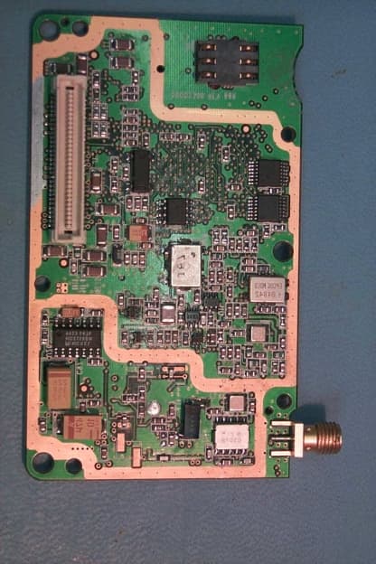
Click to zoom
Application Details
- Equipment Class
- PCB - PCS Licensed Transmitter
- Date of Grant
- Oct 19, 2000
- Application Purpose
- Original Equipment
- Date of Application
- Aug 26, 2000
- Equipment Note
- Eagle II 900/1900 MHz GSM Radio Module
- Frequency Range
- 1850.20000000 - 1909.80000000
- Company
- Xircom
- Country
- United States
Documents & Files
Document Text
Text extracted from the exhibit documents filed with the FCC. Open a document above to read the original.
Users Manual
© 2000 Xircom, Inc. All rights reserved. All trademarks and copyrights are the property of Xircom, Inc. Formerly Omnipoint Technologies, Inc. Eagle™ II GSM Radio Module Wireless GSM Communication Technical Manual Eagle II GSM Radio Module Technical Manual Preliminary Draft: 08/31/002 Part Number: 07100017 version 00.04 © 2000 Xircom, Inc. All rights reserved. All trademarks and copyrights are the property of Xircom, Inc. SAFETY PRECAUTIONS Important Safety Information The following information applies to the devices described in this manual. Always observe all standard and accepted safety precautions and guidelines when handling any electrical device. ! Save this manual: it contains important safety information and operating instructions. ! Do not expose the Eagle™ II product to open flames. ! Ensure that liquids do not spill into the devices. ! Do not attempt to disassemble the product: Doing so will void t he warranty. With the exception of the Subscriber Identification Module (SIM), this product does not contain consumer-serviceable components. Guidelines for Limiting RF Exposure The Eagle II products are GSM radio transceivers, which operate under the authority of 47 CFR Part 24, Subpart E of the FCC Rules and Regulations. When installed and operated in accordance with the instructions provided in this manual, these devices comply with current FCC regulations regarding human exposure to radio frequency radiation. The following installation and operation restrictions apply to all Eagle II products: ! This device may only be used in fixed and mobile applications. ! Portable applications, as defined by the FCC, are prohibited. ! The use of this device for desktop and other applications where the antenna can easily be relocated are considered by the FCC to be mobile applications. ! A separation distance of at least 20 cm (7.87 inches) between the antenna and the body of the user and other persons must be maintained at all times ! In FIXED applications, antenna gain is limited to a maximum of 7 dBi, with a corresponding Equivalent Isotropic Radiated Power (EIRP) of 37 dBm / 5 W. ! In MOBILE applications, antenna gain is limited to a maximum of 3 dBi, with a corresponding EIRP of 33 dBm / 2 W. ! End products must provide instructions to ensure compliance with radio frequency radiation exposure requirements. ! A warning label visible to all persons exposed to the antenna and identical to that described in this manual must be displayed on or next to the antenna. ! Separate FCC approval for RF exposure compliance is required for end products that do not meet these conditions. Antenna gain is defined as gain in dBi (dB referenced to an isotropic radiator) minus cabling loss. Eagle II GSM Radio Module Technical Manual Preliminary Draft: 08/31/003 Part Number: 07100017 version 00.04 © 2000 Xircom, Inc. All rights reserved. All trademarks and copyrights are the property of Xircom, Inc. Note: Additional care must be taken by the installer and/or user of the Eagle II products to ensure proper antenna selection and installation. Adherence to the above conditions is necessary to comply with FCC requirements for safe operation regarding exposure to RF radiation. Human Exposure Compliance Statement Xircom, Inc. Wireless Technology Group certifies that the Eagle ™II 900/1900 MHz GSM Radio Module (FCC ID: J3OEAG2919) complies with the RF hazard requirements applicable to broadband PCS equipment operating under the authority of 47 CFR Part 24, Subpart E of the FCC Rules and Regulations. This certification is contingent upon installation, operation and use of the Eagle ™ II and its host product in accordance with all instructions provided to both the OEM and end used. When installed and operated in a manner consistent with the instructions provided, the Eagle ™ II meets the maximum permissible exposure (MPE) limits for general population / uncontrolled exposure at defined in Section 1.1310 of the FCC Rules and Regulations. Disclaimer The infor mation and instructions contained within t his publication comply with all FCC, NRTL, IMEI and other applicable codes that are in effect at the time of publication. Xircom, Inc. disclaims all responsibility for any act or omissions, or for breach of law, code or regulation, including local or state codes, performed by a third party. Xircom strongly recommends that all installations, hookups, transmissions, etc., be performed by persons who are experienced in the fields of radio frequency technologies. Xircom acknowledges that the installation, setup and transmission guidelines contained within this publication are guidelines, and that each installation may have variables outside of the guidelines contained herein. Said variables must be taken into consideration when installing or using the product, and Xircom, Inc. shall not be responsible for installations or transmissions that fall outside of the parameters set forth in this publication. Xircom shall not be liable for consequential or incidental damages, injury to any person or property, anticipated or lost profits, loss of time, or other losses incurred by Customer or any third party in connection with the installation of the Products or Customer's failure to comply with the information and instructions contained herein. Eagle II GSM Radio Module Technical Manual Preliminary Draft: 08/31/004 Part Number: 07100017 version 00.04 © 2000 Xircom, Inc. All rights reserved. All trademarks and copyrights are the property of Xircom, Inc. CONTENTS SAFETY PRECAUTIONS............................................................................................2 Important Safety Information................................................................................................. 2 Guidelines for Limiting RF Exposure..................................................................................... 2 Human Exposure Compliance Statement............................................................................. 3 Disclai…
Text truncated - open the document above for the full version.
Attestation Statements
Xircom, Inc.Attestation FCC ID: J3OEAG2919Page 1 of 1 Xircom Wireless Technology Group ATTESTATION OF COMPLIANCE TESTING The Xircom, Inc. Wireless Technology Group [formerly Omnipoint Technologies, Inc. (OTI)] Eagle™ II 900/1900 MHz GSM Radio Module, FCC ID: J3OEAG2919 , has been tested to and found compliant with the requirements of the Federal Communications Commission (FCC) for receipt of a CERTIFICATION grant of equipment authorization. The FCC regulations applicable to this device are 47 CFR Part 2, Subpart J, which details equipment authorization procedures, and 47 CFR Part 24, Subpart E, which sets out the regulations governing broadband personal communications services (PCS) operating in the 1850-1910 and 1930-1990 MHz bands. All testing was performed using measurement procedures and practices consistent with the aforementioned regulations and with industry standards. Each unit manufactured and marketed will conform to the sample tested. Furthermore, the data reported in this filing is representative of the equipment being produced, within the variations that can be expected due to quantity production and testing on a statistical basis. To the best of our knowledge, we certify that the facts set forth in this document and the accompanying technical data are true and correct. We further certify that the measurements described in this document were performed under our direction and supervision at the following locations: Xircom, Inc. Wireless Technology Group (Formerly Omnipoint Technologies, Inc.) 1365 Garden of the Gods Road Colorado Springs, CO 80907 Criterion Technology(Radiated Spurious Emissions) 1350 Country Road 16 Rollinsville, CO 80474 NAME:Kelly RogersJames Youngman COMPANY:XircomXircom TITLE:Compliance EngineerCompliance Technical Lead SIGNED:____________________________________________________ DATE:August 21, 2000August 21, 2000
Attestation Statements
Xircom, Inc.Attestation FCC ID: J3OEAG2919Page 1 of 1 Xircom Wireless Technology Group ATTESTATION OF COMPLIANCE TESTING The Xircom, Inc. Wireless Technology Group [formerly Omnipoint Technologies, Inc. (OTI)] Eagle™ II 900/1900 MHz GSM Radio Module, FCC ID: J3OEAG2919, has been tested to and found compliant with the requirements of the Federal Communications Commission (FCC) for receipt of a CERTIFICATION grant of equipment authorization. The FCC regulations applicable to this device are 47 CFR Part 2, Subpart J, which details equipment authorization procedures, and 47 CFR Part 24, Subpart E, which sets out the regulations governing broadband personal communications services (PCS) operating in the 1850-1910 and 1930-1990 MHz bands. All testing was performed using measurement procedures and practices consistent with the aforementioned regulations and with industry standards. Each unit manufactured and marketed will conform to the sample tested. Furthermore, the data reported in this filing is representative of the equipment being produced, within the variations that can be expected due to quantity production and testing on a statistical basis. To the best of our knowledge, we certify that the facts set forth in this document and the accompanying technical data are true and correct. We further certify that the measurements described in this document were performed under our direction and supervision at the following locations: Xircom, Inc. Wireless Technology Group (Formerly Omnipoint Technologies, Inc.) 1365 Garden of the Gods Road Colorado Springs, CO 80907 Criterion Technology(Radiated Spurious Emissions) 1350 Country Road 16 Rollinsville, CO 80474 NAME:Kelly RogersJames Youngman COMPANY:XircomXircom TITLE:Compliance EngineerCompliance Technical Lead SIGNED:____________________________________________________ DATE:August 21, 2000August 21, 2000
Cover Letter(s)
1365 Garden of the Gods Colorado Springs, CO 80907 719.548.1200 719.548.1393 Fax August 21, 2000 Federal Communications Commission Equipment Authorization Division Application Processing Branch 7435 Oakland Mills Road Columbia, MD 21046 ATTN:Mr. Frank Coperich RE:Certification Application for FCC ID: J3OEAG2919 Dear Frank, In fulfillment of the requirements to obtain a CERTIFICATION grant of equipment authorization for equipment operating under 47 CFR Part 24, Subpart E--Broadband PCS, the Wireless Technology Group (WTG) of Xircom, Inc. [formerly Omnipoint Technologies, Inc. (OTI)] respectfully submits for your consideration the attached filing for FCC ID: J3OEAG2919. Included in this electronic submittal are Form 731, Application for Equipment Authorization; Form 159, Remittance Advice and payment in the amount of $610.00; and the documentation and technical information required by 47 CFR Part 2, Subpart J--Equipment Authorization Procedures, Section 2.1033 Application for Certification. Pursuant to Section 0.459 of the Commission's Rules, Xircom WTG respectfully requests confidentiality for the following exhibits, and that they be withheld from public inspection at the conclusion of the authorization process: Exhibit 4Tune-Up Procedure Exhibit 5Schematic Diagrams These exhibits contain material considered to be trade secrets of Xircom WTG and, as considerable effort has been expended in the development of this product, it is imperative that our competitors do not receive an unfair advantage in the marketplace at the expense of Xircom WTG. Finally, please note that although this device is capable of operating at both 900 MHz and 1900 MHz, it will only transmit within those bands where commercial GSM networks exist. Thus, within North America, this device will only transmit in the 1900 MHz PCS band (1850 – 1910 MHz) as detailed in the accompanying documentation. Should you require any further or additional information to process this application, please do not hesitate to contact me directly. I can be reached by any of the following means: Telephone:(719) 884-2751 Fax::(719) 266-8521 email:[email protected] Sincerely, James Youngman Compliance Technical Lead Xirco m Wireless Technolo gy Group
External Photos
Xircom, Inc.Exhibit 8 FCC ID: J3OEAG2919Page 1 of 5 Xircom Wireless Technology Group EXHIBIT 8 EQUIPMENT PHOTOGRAPHS This exhibit contains a series of digital photographs, as required by § 2.1033(c)(12) which reveal equipment construction and layout, including internal views showing component placement and chassis assembly. Table E18.1. Equipment photographs—photo numbers and description. Photo Number Description 1Top of Eagle II 900/1900 GSM Radio Module (shields removed) 2Bottom of Eagle II 900/1900 GSM Radio Module (shields removed) 3Top of Eagle II 900/1900 GSM Radio Module (shields in place) 4Bottom of Eagle II 900/1900 GSM Radio Module (shields in place) Xircom, Inc.Exhibit 8 FCC ID: J3OEAG2919Page 2 of 5 Xircom Wireless Technology Group Photo 1. Top of Eagle II PCB (shields removed). Xircom, Inc.Exhibit 8 FCC ID: J3OEAG2919Page 3 of 5 Xircom Wireless Technology Group Photo 2. Bottom of Eagle II PCB (shields removed). Xircom, Inc.Exhibit 8 FCC ID: J3OEAG2919Page 4 of 5 Xircom Wireless Technology Group Photo 3. Top of Eagle II (shields in place). Xircom, Inc.Exhibit 8 FCC ID: J3OEAG2919Page 5 of 5 Xircom Wireless Technology Group Photo 4. Bottom of Eagle II (shield in place).
Operational Description
Xircom, Inc.Exhibit 9 FCC ID: J3OEAG2919Page 1 of 3 Xircom Wireless Technology Group EXHIBIT 9 DETAILED DESCRIPTION OF MODULATION SYSTEM A detailed description of the modulation system employed is provided in this exhibit, per the requirements of § 2.1033(c)(13). In general, the GSM system utilizes a Time Division Multiple Access (TDMA) scheme with eight basic physical channels per carrier. Carrier separation is 200 kHz. The basic radio resource is a time slot which lasts approximately 576.9 s during which information is transmitted at a modulation rate of approximately 270.833 kb/s. The modulation scheme is Gaussian MSK (GMSK) with a bandwidth-time (BT) product of 0.3. The following description of the GSM modulation system is taken directly from Chapter 4 of Volume 1, Radio Path Physical Layer, in the Personal Communications Services, Air Interface Specification, J-STD-007. 4.0Modulation This chapter defines the theoretical requirements of the modulator, inclusive of the differential encoder. The modulator receives the bits from the encryption unit and produces and RF modulated signal. The information bits are first differentially encoded and then passed to the modulator. The modulation is GMSK (Gaussian Minimum Shift Keying) with a BT product of 0.3. 4.1Modulation Format 4.1.1Modulating Bit Rate The modulating bit rate is 1/T = 1625/6 kb/s (approximately 270.833 kb/s). 4.1.2Start and Stop of the Burst The bits contained within a burst are defined in Chapter 2. For the purpose of the modulator specification at follows, the bits entering the differential encoder prior to the first bit of the burst and following the last bit of the burst are consecutive logical ones and are denoted by the term dummy bits which define the start and end points of the useful and active parts of the burst as shown in Figure 4.1. The actual state of these bits is left to the manufacturer's implementation subject to the requirement that all performance specifications of this volume are met. Nothing is specified about the actual phase of the modulator output signal outside of the useful part of the burst. Figure 4.1 depicts the relationship between the active and useful part of the burst, the tail bits and dummy bits for a normal burst. The useful part of the burst lasts for 147 modulating bits. Xircom, Inc.Exhibit 9 FCC ID: J3OEAG2919Page 2 of 3 Xircom Wireless Technology Group 3 tail bits 000... 3 tail bits ...000 dummy bits 1111111... dummy bits ...1111111 The useful par t Output Phase The active part 1/2 bit1/2 bit Figure 4.: Normal Burst 4.1.3Differential Encoding Each data value d i = [0,1] is differentially encoded. The output of the differential encoder is: d' i = d i ⊕ d i-1 where ⊕ denotes modulo 2 addition. The modulating data value i input to the modulator is: i = 1 - 2d' i where i {-1, 1} 4.1.4Filtering The modulating data values α i as represented by Dirac pulses excite a linear filter with impulse response defined by: g(t) = h(t) ⊗ rect(t/T) where the function rect(x) is defined byrect(t/T) = 1/Tfor t < T/2 rect(t/T) = 0otherwise and ⊗ means convolution. h(t) is defined by T e th T t σπ σ 2 )( 22 2 2 − =where σ = √{ln(2)}/(2πBT) and BT = 0.3 where B is the 3 dB bandwidth of the filter with impulse response h(t) and T is the duration of the one input data bit. 4.1.5Output Phase The phase of the modulated signal is: ∑ ∫ − ∞− = i iTt duughit ' )()'( παθ Xircom, Inc.Exhibit 9 FCC ID: J3OEAG2919Page 3 of 3 Xircom Wireless Technology Group where the modulating index h is ½ (maximum phase change in radians is ½ per data interval). The time reference t' = 0 is the start of the active part of the burst as shown in Figure 4. The is also the start of the bit period of bit number 0 (the first tail bit) as defined in chapter 2. 4.1.6Modulation The modulated RF carrier, except for start and stop of the TDMA burst may therefore be expressed as: 0 )'('2cos( 2 )'( θφπ++=ttf T Ec tx o where Ec is the energy modulating bit, fo is the center frequency, and φo is a random phase and is constant during one burst.
Operational Description
Xircom, Inc.List of Exhibits FCC ID: J3OEAG2919Page 1 of 1 Xircom Wireless Technology Group LIST OF EXHIBITS EXHIBIT47 CFR §§CONTENTS 1:2.1033(a) & (c)General Information for Certification 2:2.1033(c)(3)/24.52Installation and Instruction Manual including Human Exposure Compliance Statement 3:2.1033(c)(8)DC Voltages Applied to and Currents into Final Amplifying Device *4:2.1033(c)(9)Tune-up Procedure *5:2.1033(c)(10)Schematic Diagrams 6:2.1033(c)(10)Means for Determining and Stabilizing Frequency, Suppression of Spurious Radiation, Limiting Modulation, and Limiting Power 7:2.1033(c)(11)FCC Labeling Information 8:2.1033(c)(12)Equipment Photographs 9:2.1033(c)(13)Detailed Description of Modulation System 10:2.1033(c)(14)General Measurement Information 11:2.1046/24.232(a)RF Output Power Measurements 12:2.1049Occupied Bandwidth Measurements 13:2.1051/24.238(a)Conducted Spurious Emissions Measurements 14:2.1053Radiated Spurious Emissions Measurements 15:2.1055/24.235Frequency Stability Measurements * = Exhibit filed confidentially with the FCC Xircom, Inc.Exhibit 1 FCC ID: J3OEAG2919Page 1 of 5 Xircom Wireless Technology Group EXHIBIT 1 GENERAL INFORMATION FOR CERTIFICATION The information provided in this exhibit is submitted in response to the requirements of § 2.1033 Application for a certification grant of equipment authorization. General Description of Equipment (Informative) The Xircom, Inc. Wireless Technology Group (WTG) [formerly Omnipoint Technologies, Inc. (OTI)] Eagle™ II 900/1900MHz GSM Radio Module, FCC ID: J3OEAG2919 , is an RF transceiver which operates under the authority of Part 24, Subpart E--Broadband PCS--of the FCC Rules and Regulations. Furthermore, the Eagle II complies with all applicable national and international GSM standards including, for example, J-STD-007, PCS Air Interface Specification (PCS-1900), and the current family of ETSI (European Telecommunications Standards Institute) standards for GSM 900/1800/1900 MHz Phase 2 terminals. As a wireless data terminal, the Eagle II permits access to the Global System for Mobility, or GSM, network, and ultimately the Public Switched Telephone Network (PSTN) and the internet. The Eagle II will enable a variety of fixed and mobile wireless data applications including Automated Meter Reading (AMR), alarm monitoring, telematics, e- mail and internet access. These types of PCS applications were made possible by the FCC's adoption in June 1996 of rules permitting flexible service offerings in the commercial mobile radio services (WT Docket No. 96-6, FCC 96-83, "Amendment of the Commission's Rules to Permit Flexible Service Offerings in the Commercial Mobile Radio Services, First Report and Order and Further Notice of Proposed Rulemaking," released August 1, 1996, ¶ 29). The Commission's ruling in this proceeding concluded that fixed services, such as those made possible by the Eagle II, are permissible service offerings on spectrum allocated for broadband PCS. This ruling is codified in § 24.3 which states “PCS licensees may provide any mobile communications service on their assigned spectrum. Fixed services may be provided on a co-primary basis with mobile operations.” An overview of Eagle II deployment in a GSM network is shown in Figure E1.1. Functional capabilities of the Eagle II include voice, circuit switched data up to 9.6 kpbs, and other GSM services for transmitting and receiving data (Short Message Service— SMS, and Unstructured Supplementary Service Data—USSD). The Eagle II operates over a wide temperature range (-20°C to +55°C) with a fixed DC input voltage of +4.7 VDC +/- 0.5 VDC. Connection to and communication with the host application is via a sixty pin molded connector; RF interface is through an edge-mount RF connector (SMA or MCX). Physically, the Eagle II consists of a single printed circuit board (PCB) of approximate dimensions 3.38" x 2.00" which is completely encased by top and bottom single-piece metallic shields. Access is provided for insertion of a Subscriber Identification Module (SIM) mini-card. Xircom, Inc.Exhibit 1 FCC ID: J3OEAG2919Page 2 of 5 Xircom Wireless Technology Group U ser Application Server INTERNET Eagle TM M odule Base Transceiver Station (BTS) GSM V.24 Serial I/F Mobile Switching Center (M S C ) Short Message Service Center (S M S C ) SS7, T1, etc. Base Station Controller (B S C ) PSTN SMS DATA PATH CIRCUIT SW ITCHED DATA PATH U ser MODEM Interworking Function (IWF) C ustom Packaging C ustom Application Figure E1.1. Eagle II Deployment in a GSM Network. Section 2.1033(a)Application for certification A completed FCC Form 731 “Application for Equipment Authorization” accompanies this document, both of which have been filed electronically. Section 2.1033(c)(1)Name of Applicant Applicant:Xircom, Inc. Wireless Technology Group 1365 Garden of the Gods Road Colorado Springs, CO 80907 Manufacturer:Siemens Energy & Automation, Inc. 3000 Bill Garland Road Johnson City, TN 37601 Siemens Energy & Automation is a contract manufacturer and will be the final manufacturer of the equipment described in this application. Section 2.1033(c)(2)Equipment Identification and FCC Identifier Product Name:Eagle™ II 900/1900 MHz GSM Radio Module Model Number:1110-1500 (SMA) / 1120-1500 (MCX) FCC ID: J3OEAG2919 Section 2.1033(c)(3)Eagle™ II Technical Specification Refer to Exhibit 2. Included is a statement affirming that the Eagle II complies with current FCC requirements addressing human exposure to radiofrequency radiation, pursuant to the requirements of § 24.52. Xircom, Inc.Exhibit 1 FCC ID: J3OEAG2919Page 3 of 5 Xircom Wireless Technology Group Section 2.1033(c)(4)Type of Emission (Emissions Designator) Emissions Designator: 250KGXW The maximum measured occupied bandwidth of the signal transmitted by the Eagle II is 250 kHz and thus the sequence 250K was chosen as the first four characters of the emissions designator. The emissions classification of GXW was determined using the guidance presented in § 2.…
Text truncated - open the document above for the full version.
Operational Description
Xircom, Inc.Exhibit 3 FCC ID: J3OEAG2919Page 1 of 1 Xircom Wireless Technology Group EXHIBIT 3 DC VOLTAGES AND CURRENTS INTO FINAL RADIO AMPLIFYING DEVICE As required by § 2.1033(c)(8), presented in Table E3.1 are the DC voltages applied to and the corresponding DC currents into the final RF power amplifier, over the entire range of nominal RF output powers that the Eagle II normally operates. Table E3.1. Final power amplifier—DC voltages and currents NominalFinal PA Output Power (dBm) Input Voltage (Volts) Input Current (mAmps) 302.951124 282.51867 262.11670 241.73531 221.43437 201.19352 181.00295 160.84245 140.66196 120.59178 100.49152 80.43135 60.37121 40.31108 20.2799 00.2491
Operational Description
Xircom, Inc.Exhibit 6 FCC ID: J3OEAG2919Page 1 of 3 Xircom Wireless Technology Group EXHIBIT 6 MEANS FOR DETERMINING AND STABILIZING FREQUENCY, SUPPRESSION OF SPURIOUS RADIATION, LIMITING MODULATION, AND LIMITING POWER As required by § 2.1033(c)(10), this exhibit details the methods employed to determine and stabilize frequency, suppress spurious radiation and to limit both modulation and power Means for Determining and Stabilizing Frequency No absolute frequency stability requirements are levied against broadband PCS equipment operating under the authority of Part 24, Subpart J. However, per § 24.235, the frequency stability of the equipment shall be sufficient to ensure that the fundamental emission stays within the authorized frequency block. Specifically, this is accomplished as follows: The transmit RF carrier of the Eagle II is generated by a voltage controlled oscillator (VCO) which is phase locked to a 13 MHz master reference source. This 13 MHz source is synchronized to the GSM network and, within the Eagle II, is controlled by an 11 bit DAC to keep the carrier to within ±0.1 ppm of the network reference. Measurements of the stability of the fundamental emission of the Eagle II over variations in temperature and input voltage are presented in Exhibit 14. As a GSM-compliant terminal, the stability of the Eagle II carrier is to within ±0.1 ppm (±200 Hz in 2000 MHz) of the nominal value, in accordance with GSM performance requirements (see J-STD-007, Personal Communications Services, Air Interface Specification; Volume 1, Radio Path Physical Layer, Section 7.4.1). Means for Suppression of Spurious Radiation Suppression of spurious and harmonic radiation in the Eagle II is ensured through good engineering practices and proper transmitter design, lay-out, and construction. 1. Transmitter Architecture and Design • Frequency plan of the transmitter—local oscillator frequencies were selected to minimize spurious products. • Use of an upconversion loop architecture to minimize spurious and noise power level in the PCS1900 receive band (1930-1990 MHz). • Lowpass filtering within and prior to the T/R switch to further reduce harmonics. Xircom, Inc.Exhibit 6 FCC ID: J3OEAG2919Page 2 of 3 Xircom Wireless Technology Group 2. Physical Realization of the Eagle II • Fully shielded GSM radio module construction with filtering on all signal (data, control, clock) and power supply leads. • Localized shielding over the GSM radio and digital/baseband sections. • Careful component placement and layout, multi-layer circuit board construction, microstrip signal routing, and construction techniques to eliminate cavity moding and resonances. Means for Limiting Modulation Per GSM specifications, the modulation scheme implemented by the Eagle II is Gaussian MSK (GMSK), with a bandwidth-time product of BT = 0.3. Modulation rate is 1625/6 kbps, or approximately 280.83 kbps. To minimize spreading of the spectrum, GSM standards require that the RF output spectrum meet the mask shown in Figure E6.1. In the Eagle II, modulation accuracy is maintained through the use of direct digital synthesis techniques. -70 -60 -50 -40 -30 -20 -10 0 10 0500100015002000 Frequency Offset from Carrier (kHz) Power Relative to Carrier in 30 kHz BW (dB) Figure E6.1. GSM terminal modulation mask. Xircom, Inc.Exhibit 6 FCC ID: J3OEAG2919Page 3 of 3 Xircom Wireless Technology Group Means for Limiting Power As a GSM-compliant terminal, the Eagle II is capable of transmitting at any of the 16 defined nominal RF output power levels, ranging from 30.0 dBm to 0.0 dBm, during its assigned TDMA frame. Eagle II transmitter operation (output power level) is controlled by the GSM network, and specifically by the base station to which the Eagle II is attached. Maximum RF output power of the Eagle II is set at the factory and cannot be altered or increased. Furthermore, the temporal variation in power level within each transmission (i.e., transmission burst time mask) is in accordance with GSM requirements. This is accomplished by adjusting transmitter gain through a discrete time power control loop and ramping the transmitter on and off at the beginning and ending of each burst. The power control loop is implemented using an open loop technique proven to have little effect on output power versus temperature. Maximum RF power is adjusted to within the specified tolerance during each burst, at the output power level specified by the base station.
RF Exposure Info
Xircom, Inc.Exhibit 2 FCC ID: J3OEAG2919Page 1 of 3 Xircom Wireless Technology Group EXHIBIT 2 EAGLE™ II TECHNICAL SPECIFICATION INCLUDING HUMAN EXPOSURE STATEMENT As required by § 2.1033(c)(3), provided with this filing is a copy of the draft version of the “Eagle™ II Technical Manual” which describes the features and operation of the Eagle II 900/1900 MHz GSM Radio Module. Included in this manual is a section entitled “Instructions to the Original Equipment Manufacturer (OEM).” This section provides the OEM with the necessary guidance and information to make certain that the appropriate installation and operating instructions, conditions and restrictions will be made available to the end-user. Ultimately, this documentation is designed to ensure compliance with the maximum permissible exposure (MPE) limits given in § 1.1310 for products incorporating the Eagle II GSM Radio Module in either fixed or mobile applications. Also provided on page 3 of this exhibit is a statement included in the aforementioned manual addressing human exposure to radiofrequency radiation. This information is necessary to ensure that both OEM equipment developers and end-users of the Eagle II are made aware of the dangers of exposure to radiofrequency radiation and that products containing the Eagle II must be installed and operated in accordance with the instructions provided to ensure compliance with current FCC guidelines addressing exposure to radiofrequency radiation. Pursuant to § 24.52 RF hazards, all emissions from the Eagle II, both fundamental and unwanted, a…
Text truncated - open the document above for the full version.
Contact Information
Applicant
Robert W. Paxman(Compliance Engineer)
Technical Contact
XircomJames Youngman
[email protected]719-884-2424
1365 Garden of the Gods Rd · Colorado Springs, Colorado · United States
Test Firm
Criterion Technology Corp.Lou Schornack
Technical Specifications
| # | Rule Parts | Frequency Range | Power Output | Emission | Tolerance |
|---|---|---|---|---|---|
| 1 | 24E | 1.85 GHz - 1.91 GHz | 930.00 mW | 250KGXW | 2.5000000000 ppm |
Other Applications from Xircom
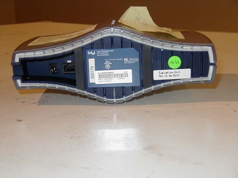
J3OWSAP2000
Jun 09, 2002WLAN Accesspoint
Equipment Class
DSS - Part 15 Spread Spectrum Transmitter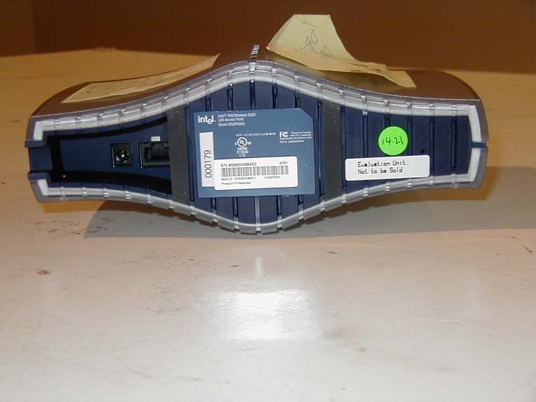
J3OWDAP5000
May 28, 2002LAN Access Point
Equipment Class
DSS - Part 15 Spread Spectrum Transmitter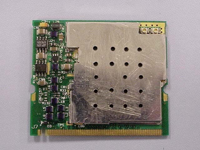
J3OWM3A5000
May 23, 2002Mini PCI Card
Equipment Class
NII - Unlicensed National Information Infrastructure TX
J3OWCB5000A
Apr 18, 2002Intel PRO/ Wireless 5000 Cardbus Adapter
Equipment Class
NII - Unlicensed National Information Infrastructure TX
J3OWPCI5000
Mar 26, 2002Wreless PCI Adapter
Equipment Class
NII - Unlicensed National Information Infrastructure TX