J3OR2BT002RealPort2 Bluetooth Adapter
Xircom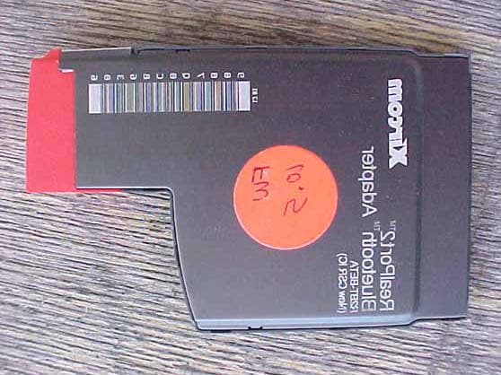
Click to zoom
Application Details
- Equipment Class
- DSS - Part 15 Spread Spectrum Transmitter
- Date of Grant
- Jul 12, 2001
- Application Purpose
- Original Equipment
- Date of Application
- Jul 12, 2001
- Equipment Note
- RealPort2 Bluetooth Adapter
- Frequency Range
- 2402.00000000 - 2480.00000000
- Company
- Xircom
- Country
- United States
Documents & Files
Document Text
Text extracted from the exhibit documents filed with the FCC. Open a document above to read the original.
Users Manual
Table of Contents | Previous Page | Next Page Bluetooth™ Adapter Table of Contents n Introduction to Bluetooth Technology n Install the Xircom Bluetooth Adapter n Make Connections Using BlueView n Bluetooth Applications n Technical Support n Specifications n Regulatory and Safety Notices n Limited Lifetime Warranty n Software License Agreement Information in this document is subject to change without notice. © 2001 Xircom, Inc. All rights reserved. The software described in this online documentation is furnished under a license and may be used or copied only in accordance with such license. Xircom is a registered trademark and CreditCard Bluetooth Adapter, RealPort2 Bluetooth Adapter, and BlueView are trademarks of Xircom, Inc. Bluetooth is a trademark owned by Telefonaktiebolaget LM Ericsson, Sweden, and licensed to Xircom, Inc. Intellisync is a registered trademark of Pumatech, Inc. Microsoft and Windows are registered trademarks of Microsoft Corporation. Other trademarks and trade names may be used in this document to refer to either the entities claiming the marks and names or their products. Xircom, Inc. disclaims any proprietary interest in trademarks and trade names other than its own. 23 May 2001 Table of Contents | Previous Page | Next Page Page 1 of 1Xircom Bluetooth Adapter - Table of Contents 6/22/2001file://C:\Compliance\Manuals\R2BT\En\help\Index.htm Table of Contents | Previous Page | Next Page Bluetooth™ Adapter Introduction to Bluetooth Technology l Introduction to Networking with Bluetooth l Bluetooth FAQ Introduction to Networking with Bluetooth Bluetooth wireless technology uses small form factor, low-cost, short-range radio links to eliminate the need for wired connections between computers. Up to eight Bluetooth devices can share data at up to 1 Mbps when they are within 32 feet or 10 meters of each other. Xircom Bluetooth Adapter and BlueView software Your Xircom Bluetooth Adapter and BlueView management software are your keys to the world of Bluetooth networking. Once you have installed the hardware and software, you can set up a personal area network (PAN) to connect your notebook to other Bluetooth devices via a secure radio link. Whenever your Bluetooth devices come within range of each other, communication can occur to automatically synchronize your schedule, phone book, and other databases and applications. With BlueView management software you can define and limit access of Bluetooth devices on your personal area network (PAN). Frequently-Asked Questions (FAQ) Q: What is Bluetooth? A: Bluetooth is the name for a short-range radio frequency (RF) technology that operates at 2.4 GHz and is capable of transmitting voice and data. The effective range of Bluetooth devices is 32 feet (10 meters). Bluetooth transfers data at a rate of up to 1 Mbps, which is from three to eight times the average speed of parallel and serial ports, respectively. Q: Why is the technology called Bluetooth? A: The heart of the Bluetooth brand identity is the name, which refers to the Danish king Harald “Bluetooth” Blaatand who unified Denmark and Norway. In the beginning of the Bluetooth wireless technology era, Bluetooth was aimed at unifying the telecom and computing industries. Ericsson and Nokia, founding members of the Bluetooth Special Interest Group, were influential in selecting the name. Q: How is Bluetooth used? A: Mobile professionals primarily use Bluetooth to wirelessly synchronize and transfer data among devices. Bluetooth can be thought of as a cable replacement technology. Typical uses include automatically synchronizing contact and calendar information among desktop, notebook and palmtop computers without connecting cables. Bluetooth can also be used to access a network or the Internet with a notebook computer by connecting wirelessly to a cellular phone or to a Bluetooth access point connected to a wired LAN. Page 1 of 4Xircom Bluetooth Adapter - Introduction 6/22/2001file://C:\Compliance\Manuals\R2BT\En\help\intro.htm Q: What benefits do I gain by using Bluetooth technology? A: Convenience & Organization l Eliminates cables – Offers wireless freedom to communicate with multiple devices. No need to hook up cables to several devices as the cables are replaced by radio links. l Organizes data - Automatically synchronizes data (with required application software) among devices without user intervention; ensures consistent, updated data in all devices. l Saves time - Transfers data 3 to 8 times faster than parallel and serial ports. l Adds flexibility – The Bluetooth personal area network is portable and travels with the user and the devices. Bluetooth devices can be used in the office, at home, and on the road. Low Cost of Ownership l No lost or broken cables to replace. l No need to stock numerous cables to support various mobile phone and computing device types. Global Wireless Solution l Bluetooth spectrum (2.4Ghz) is available in more than 95% of countries worldwide. Q: How secure is a Bluetooth network? A: Bluetooth employs several layers of data encryption and user authentication measures. Bluetooth devices use a combination of the Personal Identification Number (PIN) and a Bluetooth address to identify other Bluetooth devices. Data encryption (128-bit) can be used to further enhance the degree of Bluetooth security. The transmission scheme (FHSS) provides another level of security in itself. Instead of transmitting over one frequency within the 2.4 GHz band, Bluetooth radios use a fast frequency hopping spread spectrum (FHSS) technique, allowing only synchronized receivers to access the transmitted data. Q: What is Frequency-Hopping Spread Spectrum (FHSS)? A: Frequency Hopping Spread Spectrum (FHSS) is a spread spectrum modulation scheme that uses a narrowband carrier that changes frequency in a pattern known to both transmitter and receiver. Properly synchronized, they maintain a single logical channel. To an unintended receiver, FHSS appears as short-duration impu…
Text truncated - open the document above for the full version.
Cover Letter(s)
1. The Antenna Conducted Emissions have been retaken to show that the funamental is correctly 2402 MHz for the low channel. This was done by reducing the frequency spans for each plot. Please see the Attachement under "Test Report" 2. The Processing Gain will be uploaded under "Test report" as a separate exhibit. It was accidently omitted during the original upload, sorry. The chipset is the same as the original R2BT ========================== Question #1: RF Conducted spectrum plot submitted on page 22 of test data sheet, the fundemental frequency is 2.393GHz. 2.393GHz is outside of frequency band for 15.247 device. Please explain. Question #2: Please provide Processing Gain data per 15.247 (f) requirements. Best Regards Mike Kuo / TCB Certifier The items indicated above must be submitted before processing can continue on the above referenced application. Failure to provide the requested information within 60 days of the original e-mail date may result in application dismissal and forfeiture of the filing fee. Also, please note that partial responses increase processing time and should not be submitted. Any questions about the content of this correspondence should be directed to the e-mail address listed below the name of the sender.
Cover Letter(s)
TCB RF Exposure Review Procedure Statement FCC ID:J3OR2BT002 Transmitter Category Device Type Product Category Approval and Review Procedures Used Specific Procedures: VI Bluetooth Adapter Part 15 Portable Transmitters Section L SP(2), SP(4) with xx=5.0, SP(5), SP(6), SP(7), SP(8), SP(9) and SP(10) Grant Condition: This device and its antenna(s) must operate with a separation distance of at least 5 cm from all persons and must not be co-located or operating in conjunction with any other antenna or transmitter. End-users must be provided with specific operating instructions for satisfying RF exposure compliance . SP2 Max. measured Conducted output power as indicated in page 19 of test data sheet measuredwith Power Meter :4dBm@2402MHz (0.0025W).. Antenna Gain: 0dBi. No Cableconnection is used with Transmitter.. Antenna is self-contained within the Bluetoothadapter. No other antenna installation will be required by end users. SP4 RF exposure compliance statement can be found in User Manual The RF exposurelanguages stated in this document comply with the requirement. SP5 Total 79 hopping channels. Frequency Range : 2402 – 2480 MHz.. Complied withBluetooth Core Specification V1.0B . SP6 EUT is not a transmitter module. EUT is equipped with standard PC card connector. It canbe connected to T ype III PC card s lot or two T ype II s tacked PC card s lots . . SP7 No antenna installation is allowed by end user. SP8 User Manual has provided adequate instruction on how to connect the BlueToothAdapter. SP9 TCB has reviewed the Grant conditions and has determined the Grant conditions areapplicable to the device. SP10 By design, 5cm separation distance between BlueTooth adapter to human body can bemaintained by end user . By design , this device can provide at least 2.5cm separationdistance from person’s hands, wrists, feet and ankles. Reviewed by Mike KuoCompliance Certification ServicesJuly 12, 2001
ID Label/Location Info
RealPort2 ™ Bluetooth ™ Adapter R2BT C US LISTED E178682 I.T.E. U L APPROVAL NUMBERS ARE NOT CORRECT & ARE FOR GRAPHIC PLACEMENT ONLY MASTER TEMPLATE, R2BT A/W #832-2573-001 A ECN# 21124 05-25-01 T-A99-00-0668 U. S. and Foreign Patents Pending GZAEXXXX NYAEXXXX D01-XXXXJP 2.4 DS4 90LP0011 FOR HOME OR OFFICE USE Tested to Comply with FCC Standards CANADA ICES/NMB-003 Class/Classe (B) Canada: XXX XXXX XXXXA FCC ID: J3OR2BT002 Product of Malaysia NZ TBD
Test Report
FCC ID: J3OR2BT002 Report Number: B10619D1 114 OLINDA DRIVE, BREA, CALIFORNIA 92823 PHONE: (714) 579-0500 FAX: (714) 579-1850 Page 1 of 23 FCC PART 15, SUBPART B AND C TEST METHOD: ANSI C63.4-1992 for REALPORT 2 BLUETOOTH ADAPTER REALPORT BLUETOOTH 16 BIT TYPE III PC CARD ADAPTER Model: R2BT Prepared for XIRCOM, INC. 2300 CORPORATE CENTER DRIVE THOUSAND OAKS, CALIFORNIA 91320 COMPATIBLE ELECTRONICS INC. 114 OLINDA DRIVE BREA, CALIFORNIA 92823 (714) 579-0500 DATE: JUNE 20, 2001 REPORT APPENDICES TOTAL BODY A B C D E PAGES 23 2 2 16 55 2 100 This report shall not be reproduced except in full, without the written approval of Compatible Electronics. FCC ID: J3OR2BT002 Report Number: B10619D1 114 OLINDA DRIVE, BREA, CALIFORNIA 92823 PHONE: (714) 579-0500 FAX: (714) 579-1850 Page 2 of 23 TABLE OF CONTENTS Section / Title PAGE GENERAL REPORT SUMMARY 4 SUMMARY OF TEST RESULTS 5 1. PURPOSE 6 2. ADMINISTRATIVE DATA 7 2.1 Location of Testing 7 2.2 Traceability Statement 7 2.3 Cognizant Personnel 7 2.4 Date Test Sample was Received 7 2.5 Disposition of the Test Sample 7 2.6 Abbreviations and Acronyms 7 3. APPLICABLE DOCUMENTS 8 4. Description of Test Configuration 9 4.1 Description of Test Configuration - EMI 9 4.1.1 Cable Construction and Termination 10 5. LISTS OF EUT, ACCESSORIES AND TEST EQUIPMENT 11 5.1 EUT and Accessory List 11 5.2 EMI Test Equipment 12 6. TEST SITE DESCRIPTION 13 6.1 Test Facility Description 13 6.2 EUT Mounting, Bonding and Grounding 13 7. CHARACTERISTICS OF THE TRANSMITTER 14 7.1 Transmitter Power 14 7.2 Channel Number and Frequencies 14 7.3 Antenna Gain 14 7.4 Description of Transmitter 15 8. Test Procedures 16 8.1 RF Emissions 16 8.1.1 Conducted Emissions Test 16 8.1.2 Radiated Emissions (Spurious and Harmonics) Test 17 8.2 20 dB Bandwidth 19 8.3 Peak Output Power 19 8.4 RF Antenna Conducted Test 20 8.5 RF Band Edges 20 8.6 Carrier Frequency Separation 21 8.7 Number of Hopping Frequencies 21 8.8 Average Time of Occupancy Test 21 8.9 Spectral Density Output 22 9. CONCLUSIONS 23 FCC ID: J3OR2BT002 Report Number: B10619D1 114 OLINDA DRIVE, BREA, CALIFORNIA 92823 PHONE: (714) 579-0500 FAX: (714) 579-1850 Page 3 of 23 LIST OF APPENDICES APPENDIX TITLE A Modifications to the EUT B Additional Models Covered Under This Report C Diagrams, Charts and Photos • Test Setup Diagrams • Radiated and Conducted Emissions Photos • Antenna and Effective Gain Factors D Data Sheets E Laboratory Recognitions LIST OF FIGURES FIGURE TITLE 1 Conducted Emissions Test Setup 2 Plot Map And Layout of Radiated Site FCC ID: J3OR2BT002 Report Number: B10619D1 114 OLINDA DRIVE, BREA, CALIFORNIA 92823 PHONE: (714) 579-0500 FAX: (714) 579-1850 Page 4 of 23 GENERAL REPORT SUMMARY This electromagnetic emission test report is generated by Compatible Electronics Inc., which is an independent testing and consulting firm. The test report is based on testing performed by Compatible Electronics personnel according to the measurement procedures described in the test specifications given below and in the "Test Procedures" section of this report. The measurement data and conclusions appearing herein relate only to the sample tested and this report may not be reproduced in any form unless done so in full with the written permission of Compatible Electronics. This report must not be used to claim product endorsement by NVLAP or any other agency of the U.S. Government. Device Tested: RealPort2 Bluetooth 16 Bit Type III PC Card Adapter Model: R2BT S/N: Pre-Production Modifications: The EUT was not modified in order to meet the specifications. Product Description: The EUT is similar to the R2BT with the FCC-ID: J3OR2BT001 except it has a maximum power output of 2.5 mW, instead of 1 mW. Manufacturer: Xircom, Inc. 2300 Corporate Center Drive Thousand Oaks, California 91320 Test Dates: June 13 and 19, 2001 File # For Canada IC2154-D Test Specifications : EMI requirements Limits: EN 55022: 1998 Class B; and Subpart C, sections 15.205, 15.207, 15.209, and 15.247 Test Procedure: ANSI C63.4: 1992 Test Deviations: The test procedure was not deviated from during the testing. FCC ID: J3OR2BT002 Report Number: B10619D1 114 OLINDA DRIVE, BREA, CALIFORNIA 92823 PHONE: (714) 579-0500 FAX: (714) 579-1850 Page 5 of 23 SUMMARY OF TEST RESULTS TEST DESCRIPTION RESULTS 1 Conducted RF Emissions, 450 kHz – 30 MHz Complies with the Class B limits of EN 55022: 1998 2 Spurious Radiated RF Emissions, 30 MHz – 1000 MHz Complies with the Class B limits of EN 55022: 1998 3 Spurious Radiated RF Emissions, 10 kHz – 30 MHz and 1000 MHz – 25000 MHz Complies with the relevant requirements of FCC Title 47, Part 15, Subpart C, section 15.247(c) 4 Fundamental and Emissions produced by the intentional radiator in non-restricted bands, 10 kHz – 25 GHz Complies with the relevant requirements of FCC Title 47, Part 15, Subpart C, section 15.247(c) 5 Emissions produced by the intentional radiator in restricted bands, 10 kHz – 25 GHz Complies with the relevant requirements of FCC Title 47, Part 15, Subpart C, section 15.205, 15.209(a), and section 15.247 (c) 6 20 dB Bandwidth Complies with the relevant requirements of FCC Title 47, Part 15, Subpart C, section 15.247 (a)(1)(ii) 7 Peak Power Output Complies with the relevant requirements of FCC Title 47, Part 15, Subpart C, section 15.247 (b)(1) 8 Channel Hopping Separation Complies with the relevant requirements of FCC Title 47, Part 15, Subpart C, section 15.247 (a)(1) and 15.247 (a)(1)(ii) 9 Average Time of Occupancy Complies with the relevant requirements of FCC Title 47, Part 15, Subpart C, section 15.247 (a)(1)(ii) 10 Peak Power Spectral Density Conducted from the Intentional Radiator to the Antenna Complies with the relevant requirements of FCC Title 47, Part 15, Subpart C, section 15.247 (d) FCC ID: J3OR2BT002 Report Number: B10619D1 114 OLINDA DRIVE, BREA, CALIFORNIA 92823 PHONE: (714) 579-0500 FAX: (714) 579-1850 Page 6 of 23 1. PURPOSE This document is a qualification test report based on the Electromagnet…
Text truncated - open the document above for the full version.
Test Report
FCC ID: J3OR2BT002 Report Number: B10619D1 114 OLINDA DRIVE, BREA, CALIFORNIA 92823 PHONE: (714) 579-0500 FAX: (714) 579-1850 APPENDIX D DATA SHEETS FCC ID: J3OR2BT002 Report Number: B10619D1 114 OLINDA DRIVE, BREA, CALIFORNIA 92823 PHONE: (714) 579-0500 FAX: (714) 579-1850 RADIATED EMISSIONS FOR THE TRANSMITTER DATA SHEETS RADIATED EMISSIONS (FCC SECTION 15.205 AND 15.247) COMPANY DATE 6/19/2001 EUT DUTY CYCLE N/A MODEL PEAK TO AVG N/A S/N TEST DIST. 3 METERS TEST ENGINEER LAB D Frequency Peak Antenna Antenna EUT EUT EUT Antenna Cable Amplifier *Corrected Delta Spec Reading Polar. Height Azimuth Axis Tx Factor Loss Gain Reading ** Limit MHz (dBuV) (V or H) (meters) (deg rees) (X,Y,Z) C hannel (dB) (dB) (dB) (dBuV/m) (dB) (dBuV/m) Comments 2402.0000 60.5 AH 1.0 180 X LOW 30.5 3.6 0.0 94.6 2402.0000 61.4 AV 1.0 180 X LOW 30.5 3.6 0.0 95.5 2442.0000 56.7 AH 1.5 180 X MID 30.6 3.5 0.0 90.8 2442.0000 57.2 AV 1.0 90 X MID 30.6 3.5 0.0 91.3 2480.0000 49.1 AH 1.5 180 X HIGH 30.7 3.5 0.0 83.3 2480.0000 53.1 AV 1.0 180 X HIGH 30.7 3.5 0.0 87.3 * CORRECTED READING = METER READING + ANTENNA FACTOR + CABLE LOSS - AMPLIFIER GAIN ** DELTA = SPEC LIMIT - CORRECTED READING PAGE 1 Average (A) or Quasi- Peak (QP) N/AXircom, Inc.REALPORT2 BLUETOOTH 16 BIT TYPE III PC CARD ADAPTERR2BTKYLE FUJIMOTO Doc. No.: EMI_PART15TX-B-0-50 Rev. A 04/11/00 RADIATED EMISSIONS (FCC SECTION 15.205 AND 15.247) COMPANY DATE 6/19/2001 EUT DUTY CYCLE N/A MODEL PEAK TO AVG N/A S/N TEST DIST. 3 METERS TEST ENGINEER LAB D Frequency Peak Antenna Antenna EUT EUT EUT Antenna Cable Amplifier *Corrected Delta Spec Reading Polar. Height Azimuth Axis Tx Factor Loss Gain Reading ** Limit MHz (dBuV) (V or H) (meters) (deg rees) (X,Y,Z) C hannel (dB) (dB) (dB) (dBuV/m) (dB) (dBuV/m) Comments 4804.0000 49.5 38.7 AH 1.0 90 X LOW 34.2 5.4 32.0 46.2 -7.8 54.0 4804.0000 53.9 41.6 AV 1.0 90 X LOW 34.2 5.4 32.0 49.2 -4.8 54.0 4884.0000 47.1 36.1 AH 1.5 90 X MID 34.4 5.6 32.1 44.0 -10.0 54.0 4884.0000 48.7 37.9 AV 1.5 90 X MID 34.4 5.6 32.1 45.7 -8.3 54.0 4960.0000 47.4 36.2 AH 1.5 90 X HIGH 34.7 5.7 32.2 44.3 -9.7 54.0 4960.0000 50.4 38.9 AV 1.5 90 X HIGH 34.7 5.7 32.2 47.0 -7.0 54.0 * CORRECTED READING = METER READING + ANTENNA FACTOR + CABLE LOSS - AMPLIFIER GAIN ** DELTA = SPEC LIMIT - CORRECTED READING PAGE 2 Xircom, Inc.REALPORT2 BLUETOOTH 16 BIT TYPE III PC CARD ADAPTERR2BTN/AKYLE FUJIMOTO Average (A) or Quasi- Peak (QP) Doc. No.: EMI_PART15TX-B-0-50 Rev. A 04/11/00 RADIATED EMISSIONS (FCC SECTION 15.205 AND 15.247) COMPANY DATE 6/19/2001 EUT DUTY CYCLE N/A MODEL PEAK TO AVG N/A S/N TEST DIST. 3 METERS TEST ENGINEER LAB D Frequency Peak Antenna Antenna EUT EUT EUT Antenna Cable Amplifier *Corrected Delta Spec Reading Polar. Height Azimuth Axis Tx Factor Loss Gain Reading ** Limit MHz (dBuV) (V or H) (meters) (deg rees) (X,Y,Z) C hannel (dB) (dB) (dB) (dBuV/m) (dB) (dBuV/m) Comments 7206.0000 44.1 31.7 AH 1.5 180 X LOW 38.7 8.1 32.5 46.0 -8.0 54.0 7206.0000 44.7 33.2 AV 2.0 0 X LOW 38.7 8.1 32.5 47.5 -6.5 54.0 7326.0000 49.1 36.1 AH 1.5 90 X MID 38.6 8.1 32.7 50.1 -3.9 54.0 7326.0000 49.9 37.3 AV 1.5 90 X MID 38.6 8.1 32.7 51.3 -2.7 54.0 7440.0000 45.7 33.2 AH 1.5 90 X HIGH 38.6 7.9 32.9 46.8 -7.2 54.0 7440.0000 47.1 34.8 AV 1.5 0 X HIGH 38.6 7.9 32.9 48.4 -5.6 54.0 * CORRECTED READING = METER READING + ANTENNA FACTOR + CABLE LOSS - AMPLIFIER GAIN ** DELTA = SPEC LIMIT - CORRECTED READING PAGE 3 Xircom, Inc.REALPORT2 BLUETOOTH 16 BIT TYPE III PC CARD ADAPTERR2BTN/AKYLE FUJIMOTO Average (A) or Quasi- Peak (QP) Doc. No.: EMI_PART15TX-B-0-50 Rev. A 04/11/00 RADIATED EMISSIONS (FCC SECTION 15.205 AND 15.247) COMPANY DATE 6/19/2001 EUT DUTY CYCLE N/A MODEL PEAK TO AVG N/A S/N TEST DIST. 3 METERS TEST ENGINEER LAB D Frequency Peak Antenna Antenna EUT EUT EUT Antenna Cable Amplifier *Corrected Delta Spec Reading Polar. Height Azimuth Axis Tx Factor Loss Gain Reading ** Limit MHz (dBuV) (V or H) (meters) (deg rees) (X,Y,Z) C hannel (dB) (dB) (dB) (dBuV/m) (dB) (dBuV/m) Comments 9608.0000 43.4 AH 2.5 90 X LOW 39.6 9.2 30.9 61.3 -14.2 75.5 9608.0000 44.7 AV 1.5 90 X LOW 39.6 9.2 30.9 62.6 -12.9 75.5 9768.0000 43.3 AH 1.5 90 X MID 39.7 9.4 31.2 61.1 -10.2 71.3 9768.0000 44.8 31.8 AV 1.5 90 X MID 39.7 9.4 31.2 49.6 -21.7 71.3 9920.0000 43.7 30.2 AH 1.5 90 X HIGH 39.7 9.8 31.5 48.3 -19.0 67.3 9920.0000 44.2 33.3 AV 1.5 90 X HIGH 39.7 9.8 31.5 51.4 -15.9 67.3 * CORRECTED READING = METER READING + ANTENNA FACTOR + CABLE LOSS - AMPLIFIER GAIN ** DELTA = SPEC LIMIT - CORRECTED READING PAGE 4 Emissions found after the4th Harmonic Xircom, Inc.REALPORT2 BLUETOOTH 16 BIT TYPE III PC CARD ADAPTERR2BTN/AKYLE FUJIMOTO Average (A) or Quasi- Peak (QP) Note:No Harmonics nor Doc. No.: EMI_PART15TX-B-0-50 Rev. A 04/11/00 Page: 1 of 1 Test location: Compatible Electronics Customer : XIRCOM, INC. Date : 6/13/2001 Manufacturer : XIRCOM, INC. Time : 9.42 EUT name : REALPORT2 BLUETOOTH ADAPTER Model: R2BT Specification: Cispr_B Test distance: 10.0 mtrs Lab: D Distance correction factor(20*log(test/spec)) : 0.00 Test Mode : REALPORT2 BLUETOOTH 16 BIT TYPE III PC CARD ADAPTER VERTICAL POLARIZATION 30 MHz TO 1000 MHz SPURIOUS EMISSIONS TEMPERATURE 68 DEGREES F., RELATIVE HUMIDITY 70% TESTED BY: KYLE FUJIMOTO Pol Freq Rdng Cable Ant Amp Cor'd limit Delta loss factor gain rdg = R = L R-L MHz dBuV dB dB dB dBuV dBuV/m dB 1V 85.37 46.40 1.81 8.12 38.55 17.78 30.00 -12.22 2V 109.41 50.80 2.08 9.44 38.89 23.43 30.00 -6.57 3V 114.64 50.70 2.12 9.88 38.99 23.71 30.00 -6.29 4V 120.09 47.20 2.16 10.35 39.10 20.61 30.00 -9.39 5V 145.29 49.90 2.44 12.83 38.88 26.29 30.00 -3.71 6V 150.09 50.00 2.50 12.96 38.80 26.66 30.00 -3.34 7V 247.95 46.70 3.58 16.35 38.80 27.83 37.00 -9.17 8V 344.12 48.40 4.06 14.70 38.90 28.26 37.00 -8.74 9V 368.76 45.90 4.18 15.68 38.79 26.97 37.00 -10.03 10V 405.62 44.20 4.31 16.90 38.59 26.82 37.00 -10.18 11V 442.45 42.60 4.38 16.83 38.52 25.29 37.00 -11.71 12V 449.87 45.00 4.40 16.82 38.50 27.72 37.00 -9.28 13V 456.12 43.80 4.44 16.81 38.52 26.53 37.00 -10.47 14V 4…
Text truncated - open the document above for the full version.
Test Report
Page 1 of 11 PG Results 23 March 2001 Filename: BlueCore01_BC01b_PG_Results_v2.1 MEMORANDUM Distribution:Peter Flittner, Robert Young, James Collier cc: Prepared By:Alex Busteed Subject:Results of Processing Gain Tests for FCC Qualification 1 INTRODUCTION This memo presents the results of the Processing Gain (PG) tests carried out for FCC qualification of the Cambridge Silicon Radio BC01B Bluetooth chip. The FCC states that the PG from a hybrid Bluetooth receiver must be greater than 17 dB when measured in accordance with the Continuous Wave (CW) jamming margin method. Testing of the BC01b has found the PG due to the DS section to be approximately 5 dB and the PG due to the FH part to be approximately 15 dB. It is therefore concluded that the BC01B complies with the FCC PG requirements for radio communication systems. The rest of this paper outlines the PG measurement technique and discusses the test results. Appendix A contains a list of test equipment and Appendix B contains a printout of the measurement results. 2 METHOD 2.1 PG Definition The Processing Gain from a frequency hopping communication system is derived from two parts, the FH section and the DS section. The PG due to FH is given by a simple equation and is constant. However measurement of the PG due to DS is a little more complex. One technique is to use the CW jamming margin method. This method measures PG due to DS using the following algorithm: A CW signal generator is stepped in 50kHz increments across the passband of the system, recording at each point the generator level required to produce the 0.1% Packet Error Rate (PER). This is the jammer level. This level is then referenced to the output power of the intended Bluetooth signal and the Jammer to Signal Ratio JSR is thus calculated. The worst 4 Page 2 of 11 PG Results 23 March 2001 JSR measurements are discarded and the worst remaining JSR is used to calculate the PG due to DS as follows: sysp LJSRSNRG++= min where G p = the processing gain of the system, SNR = the signal to noise ratio required for 0.1% BER, JSR min = minimum J/S ratio and L sys = system losses. 2.2 PG Measurement Technique Figure 1 provides an overview of the PG measurement technique. The measurement is performed in two parts, measurement of the system SNR and measurement of JSR min . Figure 1: PG Measurement Technique The system SNR is calculated using the following algorithm. Generate Bluetooth PRBS-9 packets using a BC01B emulator (1) and a Vector Signal Generator (2). Combine this signal with white noise of a constant level, which is generated using a noise source (4) and a CW Signal Generator (3). Then vary the level of the Bluetooth signal until the BER measured by the BC01B (7) is 0.1%. The resulting SNR is the signal level divided by the Noise level. Page 3 of 11 PG Results 23 March 2001 The JSR for a given jamming frequency is calculated using the following algorithm. Generate Bluetooth PRBS-9 packets using the BC01B emulator (1) and the Vector Signal Generator (2). Combine this signal with a constant CW tone at the jamming frequency using a CW Signal Generator (5) and a combiner (6). Then vary the level of the Bluetooth signal until the PER measured by the Casira Bluetooth Module (7) is 0.1%. The resulting JSR is the signal level divided by the jamming level. 3 RESULTS 3.1 Overview The measurements found that the PG due to DS caused by the access code in page and inquiry mode is found to be approximately 5dB when the access code is a relatively random mixture of 1's and 0's. A random access code causes the most Inter Symbol Interference (ISI) and hence the worst PG for a hybrid system. Therefore only the results for this access code are used in the PG calculation. The PG due to FH is given as PG FH = 10 log 10 (number of frequency hops) The number of hops in a Bluetooth system is 32, therefore the PG due to FH is approximately 15 dB. When this is added to the PG due to DS, the total PG for the BC01B is approximately 20 dB, above the minimum PG requirement for FCC qualification. 3.2 Detailed Results Test Date:17/11/00 Sample Time: 30 seconds Access Code: c6967e Signal Frequency:2.432GHz Receiver Sensitivity: -88.7 dBm Jammer Signal Level:-85.7 dBm Measured SNR: 18.8dB System Losses: 2dB To calculate processing gain, ignore the worst 20% of data points and then apply the following formula: Page 4 of 11 PG Results 23 March 2001 sysp LJSRSNRG++= min Where G p = Processing Gain of the module SNR = signal to noise ratio of the module JS min = minimum J/S ratio after the worst 20% of J/S samples have been discarded L sys = System losses A total of 20 samples were taken by stepping the jamming signal frequency offsets in 50kHz increments over the bandwidth of the receiver. The worst 4 samples were found at –500kHz, -450kHz, -400kHz and 500kHz and were discarded. The remaining minimum J/S ratio was found to be -15.4dB at an offset of +350kHz Thus, the processing gain due to direct sequence spreading in page and inquiry mode is dBG p 4.524.158.18=+−= -500-400-300-200-1000100200300400500 -30 -25 -20 -15 -10 -5 0 5 Jamming Frequency Offset (kHz) J/S (dBs) J/S ratio performance for Processing Gain FCC Testing Page 5 of 11 PG Results 23 March 2001 APPENDIX A - TEST EQUIPMENT LIST Reference:Instrument TypeName 1BlueCore Emulator BoardN/A 2Vector Signal GeneratorIFR2052 3CW Signal GeneratorIFR2025 4White Noise GeneratorHP33120A 5RF MixerM8HC-7 6RF Combiner6 dB loss combiner 7Bluetooth Motherboard and BC01B Module Casira Development Kit 85V, 4A DC Power SupplyN/A 9Spectrum AnalyserHP E4405B Page 6 of 11 PG Results 23 March 2001 APPENDIX B - TEST RESULTS Timestamp: 14:42.43, 16/11/2000 Signal Freq = 2.432 GHz Jammer Level = -85.7 dBm Jammer Offset = -500 kHz Level = -68.7 dBm BER = 0.03% PER = 0.01% SER1 = 0.01% SER2 = 0.01% Level = -70.7 dBm BER = 0.32% PER = 0.79% SER1 = 0.79% SER2 = 0.79% Level = -69.7 dBm BER = 0.11% PER = 0.18% SER1 = 0.18% SER2 = 0.18% Level = -68.7 dBm BER = 0.04% PER = 0.03% SER1 …
Text truncated - open the document above for the full version.
Contact Information
Applicant
Robert W. Paxman(Compliance Engineer)
Test Firm
Compatible ElectronicsScott McCutchan
714-579-0500Fax: 714-579-1850
Technical Specifications
| # | Rule Parts | Frequency Range | Power Output |
|---|---|---|---|
| 1 | 15C | 2.40 GHz - 2.48 GHz | 2.50 mW |
Other Applications from Xircom
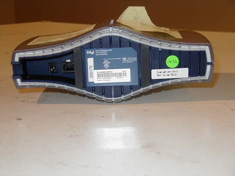
J3OWSAP2000
Jun 09, 2002WLAN Accesspoint
Equipment Class
DSS - Part 15 Spread Spectrum Transmitter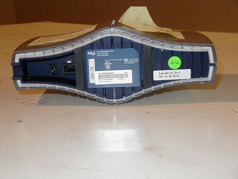
J3OWDAP5000
May 28, 2002LAN Access Point
Equipment Class
DSS - Part 15 Spread Spectrum Transmitter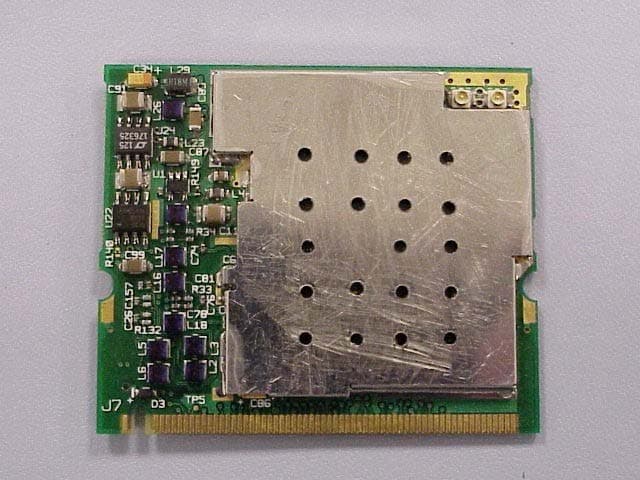
J3OWM3A5000
May 23, 2002Mini PCI Card
Equipment Class
NII - Unlicensed National Information Infrastructure TX
J3OWCB5000A
Apr 18, 2002Intel PRO/ Wireless 5000 Cardbus Adapter
Equipment Class
NII - Unlicensed National Information Infrastructure TX
J3OWPCI5000
Mar 26, 2002Wreless PCI Adapter
Equipment Class
NII - Unlicensed National Information Infrastructure TX