J3OSWE1100802.11b Wireless Ethernet Adapter
Xircom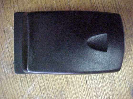
Click to zoom
Application Details
- Equipment Class
- DSS - Part 15 Spread Spectrum Transmitter
- Date of Grant
- May 08, 2001
- Application Purpose
- Original Equipment
- Date of Application
- May 08, 2001
- Equipment Note
- 802.11b Wireless Ethernet Adapter
- Frequency Range
- 2412.00000000 - 2462.00000000
- Company
- Xircom
- Country
- United States
Documents & Files
Document Text
Text extracted from the exhibit documents filed with the FCC. Open a document above to read the original.
Users Manual
Product Specifications Xircom SpringPort™ Wireless Ethernet Adapter Model SWE1100 SpringPort™ Wireless Ethernet module System Requirements Handspring™ Visor™ handheld, Palm® Operating System Compatible with all Visor models Standard IEEE 802.11b high-rate standard for Wireless Local Area Networks Network Architecture Types Supports peer-to-peer networking and communication to wired networks via access points Data Rates Supported 1,2,5.5 and 11 Mbps Modulation 11 Mbps and 5.5 Mbps: CCK; 2 Mbps: DQPSK; 1 Mbps: DBPSK Wireless Medium Direct Sequence Spread Spectrum (DSSS) Media Access Protocol Carrier Sense Multiple Access with Collision Avoidance (CSMA/CA) Security Supports 0, 40 or 128-bit WEP (Wired Equivalent Privacy) encryption Bundled Software AvantGo and MultiMail SE Frequency Band 2400-2483.5 MHz Operating Channels 11 channels (US, Canada) 13 channels (ETSI) 4 channels (France) 14 channels (Japan) Simultaneous Channels Three non-overlapping channels Roaming IEEE 802.11b compliant Typical Range at 11 Mbps Up to 300 ft (90 m) in open environments and 100 ft (30 m) in office environments Typical Range at 1 Mbps Up to 1000 ft (300 m) in open environments and 300 ft (90 m) in office environments Battery Li-ION rechargeable (2 hours of continuous transmission) LED Indicators Active, Status and Charging Certifications FCC Class B, FCC Part 15.247, Canada ICES Class B, CE, UL, CSA Call for other information outside the USA Warranty One-year limited warranty 812-1736-001A 1 SpringPort Wireless Ethernet Module Regulatory and Safety Notices FCC Regulations - Part 15 Declaration of Conformity (DoC) Xircom, Inc. declares that the equipment described in this document is within the requirements of the Code of Federal Regulations listed below: Title 47 Part 15, Subpart B, Class B for a digital device. This declaration is based upon compliance of the Xircom SpringPort Wireless Ethernet module model SWE1100 to the above standards. Xircom has determined that this model has been shown to comply with the applicable technical standards if no unauthorized change is made in the equipment and if the equipment is properly maintained and operated. These units are identical to the units tested and found acceptable with the applicable standards. Records maintained by Xircom continue to reflect that units being produced under this Declaration of Conformity, within the variation that can be expected due to quantity production and tested on a statistical basis, continue to comply with the applicable technical standards. R.W. Bass, Vice President, Operations, Xircom, Inc., 2300 Corporate Center Drive, Thousand Oaks, California 91320 U.S.A. Federal Communications Commission Information for the User This device complies with Part 15 rules. Operation is subject to the following two conditions: 1. This device may not cause harmful interference, and 2. This device must accept any interference received, including interference that may cause undesired operation. This equipment has been tested and found to comply with the limits of a Class B digital device, pursuant to Part 15 of the FCC Rules. These limits are designed to provide reasonable protection against harmful interference when the equipment is operated in a residential environment. This equipment generates, uses, and radiates radio frequency energy, and if not installed and used in accordance with the instructions, may cause harmful interference. However, there is no guarantee that interference will not occur. If this equipment does cause interference to radio or television reception, which can be determined by turning the equipment on and off, the user is encouraged to correct the interference by one of the following measures: • Reorient or relocate the receiving antenna. • Increase separation between the equipment and receiver. • Connect the equipment into an outlet on a circuit different from which the receiver is connected. • Consult the dealer or an experienced radio/TV technician. CAUTION: The Part 15 radio device operates on a non-interference basis with other devices operating at this frequency. Any changes or modification to said product not expressly approved by Xircom could void the user's authority to operate this device. 812-1723-001A 2 Canadian Department of Communications Industry Canada (IC) Notice This digital apparatus does not exceed the Class B limits for radio noise emissions from digital apparatus set out in the Radio Interference Regulations of the Canadian Department of Communications. Le présent appareil numérique n'émet pas de bruits radioélectriques dépassant les limites applicables aux appareils numériques de Classe B prescrites dans le règlement sur le brouillage radioélectrique édicté par le Ministère des Communications du Canada. This device complies with Class B Limits of Industry Canada. Operation is subject to the following two conditions: 1. This device may not cause harmful interference, and 2. This device must accept any interference received, including interference that may cause undesired operation. The device is certified to the requirements of RSS-139-1 and RSS-210 for 2.4 GHz spread spectrum devices. The use of this device in a system operating either partially or completely outdoors may require the user to obtain a license for the system according to the Canadian regulations. For further information, contact your local Industry Canada office. European Community - CE Mark Declaration of Conformity Xircom, Inc. declares that the equipment described in this document is in conformance with the requirements of the European Council Directive listed below: 73/23/EEC Low Voltage Directive with Amendment 93/68/EEC 89/336/EEC EMC Directive with Amendments 92/31/EEC and 93/68/EEC 1999/5/EC Radio and Telecommunications Terminal Equipment Directive This declaration is based upon compliance of the product to the following standards: ETS 300 328/A1 (1997-07, Edition 2) Radio Equipment and Systems (RES); wideband transmission systems; tec…
Text truncated - open the document above for the full version.
Cover Letter(s)
From: Mike Kuo Sent: Monday, April 30, 2001 6:33 PM To: '[email protected]'; '[email protected]' Cc: Mike Kuo Subject: RE: Xircom, FCC ID:J3OSWE1100, AN01T1314. 1. The request for confidentiality letter will be uploaded as a cover letter exhibit in *.PDF format 2. A procedure has been provided to enusre the peak power output will be less than 0.018W. Please see the tune-up procedure attachment. 3. The user's manual has been revived to include the technical specifications of the unit. The revised user's manual will be uploaded as an attachment. 4. The operational description for the SWE1100 will also be uploaded as an attachment. Also uploaded will be the antenna specification and antenna gain. If you have any further questions, please either call us at (714) 579-0500 or E-mail us at the above addresses -----Original Message----- From: CERTADM Sent: Monday, April 30, 2001 6:29 PM To: '[email protected]'; '[email protected]' Cc: Mike Kuo Subject: Xircom, FCC ID:J3OSWE1100, AN01T1314. Notice_content ------------- Question #1: This application did not request for Confidentiality per CFR 47, section 0.459 of FCC rules. However, the document submitted contains information that were requested for confidentiality under FCC ID:LDK102039. There were four documents were requested for confidentiality under FCC ID:LDK102039, they are : Theory of operation, Block Diagram, Schematic Diagram and Tune-up Procedures. Please provide a request for confidentiality letter to make sure the documents submitted for this application is consistance with FCC ID:LDK102039. Question #2:Since the Peak output power measured is lower than the transmitter module on file with FCC, please provide manufactuer tune-up procedure to ensure the peak output will be less than 0.018W. In addition, please provide a statement from manufacturer that the software used in adjusting output power is not available to the end user. Question #3 User Manual : The information contains in the user manual file only include the regulatory compliance information. Please provide the user manual with technical specifications. Question #4: The operational description ( theory of operation ) submitted is written for Transmitter module. Please provide operational description for SWE1100 model and make sure to include the antenna specification, gain and frequency range information. Best Regards Mike Kuo / TCB Certifier The items indicated above must be submitted before processing can continue on the above referenced application. Failure to provide the requested information within 60 days of the original e-mail date may result in application dismissal and forfeiture of the filing fee. Also, please note that partial responses increase processing time and should not be submitted. Any questions about the content of this correspondence should be directed to the e-mail address listed below the name of the sender.
Cover Letter(s)
TCB RF Exposure Review Procedure Statement FCC ID:J3OSWE1100 Transmitter Category Device Type Product Category Approval and Review Procedures Used Specific Procedures: VI Wireless Ethernet Adaptor for PDA Part 15 Portable Transmitters Section L SP(2), SP(4) with xx=5.0, SP(5), SP(6), SP(7), SP(8), SP(9) and SP(10) • Grant Condition : This device and its antenna(s) must operate with a separation distance of at least 5 cm from all persons and must not be co-located or operating in conjunction with any other antenna or transmitter. End-usersmust be provided with specific operating instructions for satisfying RF exposure compliance i . SP2 EUT is a 2.4GHz Direct Sequence Spread Spectrum 802.11b Wireless Ethernet Adapter to be usedwith PDA. No duty cycle needs to be considered. Applicable FCC rule parts: Part 15, section15.247. Output power ratings have been verified by comparing Page 65 of test report. Outputpower was measured with Power Meter. The highest rating measured is 12.6dBm@Channel11(18mW). SP4 Page 4 of Owner Manual. RF exposure information to user specified 5 cm separation distance. SP5 Device is operating at single 2.4GHz frequency band. Operating Frequency Range: 2412 – 2462MHz SP6 Device is a Ethernet Adapter. Not a transmitter module. SP7 Device is designed to have two types of antenna. Antenna specifications provided by the applicantare detailed enough to ensure the antenna can not be changed by the end user. All two antennas areequipped with unique connector. SP8 Page 4 of Owner Manual. SP9 Grant conditions have been reviewed by TCB and has made the determination that device compliedwith RF Exposure review procedures. SP10 By design, device and its antenna can ensure the separation distance of 2.5 cm from a person’shands, wrists, feet and ankles. Reviewed by Mike KuoCompliance Certification ServicesMay 8, 2001
ID Label/Location Info
FOR HOME OR OFFICE USE Tested to Comply with FCC Standards SpringPort ™ Wireless Ethernet SWE1100 C US LISTED E178682 E178682 I.T.E.I.T.E. U L CAUTION! RISK OF EXPLOSION IF BATTERY IS REPLACED BY INCORRECT TYPE. DISPOSE OF USED BATTERIES ACCORDING TO THE MANUFACTURER'S INSTRUCTIONS. A/W# 832-2623-001A FAB #830-1744-001 ECN 22311 Wirelesss by Cisco Systems FCC ID: J3OSWE1100 CANADA ICES/NMB-003 Class/Classe (B)
Parts List/Tune Up Info
Page 1 Xircom, Inc. Performance Summary for: Springport Wireless Ethernet Folded Dipole Antenna Intellectual Property Disclosure in Process Antenna Mounted in Module Page 2 SWE Antenna Description The performance characteristics of the SWE folded dipole antenna have been optimized with the SWE SpringPort module mated to the HandSpring Visor PDA. When installed in the SWE module, the antenna becomes a matching element to the SWE module PC card and the radiated fields propagate across the module PC card and then radiate off the leading edge of that card. The resulting radiation pattern exhibits a monopole type radiation pattern with a null along the major axis of the module and pattern peaks at approximately 30º to 50º from the major axis in the direction of the SWE card. The radiated field thus observed is polarized along the axis of the card. DTA 3.0 Specification Summary Electrical Frequency 2400-2480MHz Nominal Peak Antenna Gain 2.0 dBi Nominal 3 dB Beamwidth E-Plane N/A (Bifurcated Beam Pattern) H-Plane 360º Polarization Vertical (Along Major Axis of Card) Input VSWR 1.4:1 Max Input Impedance 50 ohms Maximum Power Input 10 watts PIM N/A Static Protection Element and Feed are DC Grounded Mechanical Dimensions 7.5mm L x 40.4mm W (etched on circuit board material) Input Connector MMCX Edge Mount Weight N/A Wind Area N/A Wind Load N/A 0 θ plot j 0 10 20 30 40 50 60 70 80 90 100 110 120 130 140 150 160 170 180 190 200 210 220 230 240 250 260 270 280 290 300 310 320 330 340 350 Phi = 0 SWE in Handspring θ plot j 0 10 20 30 40 50 60 70 80 90 100 110 120 130 140 150 160 170 180 190 200 210 220 230 240 250 260 270 280 290 300 310 320 330 340 350 Phi = 0 SWE in Handspring E-Plane Cut (Phi = 0º ) E-Plane Cut (Phi = 90º) Co-Polarized Component T e c h n i c a l S p e c i f i c a t i o n S h e e t 2.4 GHz Bluetooth™ Antenna — P/N 100902 Ultima™ Series Antennas This small embedded antenna provides the most reliable, easy-to-use, and adjustment-free antenna technology for handling during assembly and implementation by developers. Typical Mounting Typical VSWR Typical Pattern Features •Small and lightweight •No tuning components •Available in tape and reel or tray packing for automatic mounting Electrical Frequency Range2400 – 2500 MHz Peak Gain (1) 0 dBi VSWR (1) less than 2.0:1 Polarizationlinear Azimuth Beamwidthomnidirectional Power Handling10 Watt cw Feed Point Impedance50 Ohms unbalanced Note (1) Figures dependent on ground plane size Mechanical Size18.2 x 3.9 x 1.6 mm Weightless than 1 g Mountingsurface mount technology Dimensions Typical Pad Layout © 2000 RangeStar Wireless, Inc. RangeStar, RangeStar Wireless, and Ultima are trademarks or registered trademarks of RangeStar Wireless, Inc. All rights reserved. Protected by one or more U.S. Patents 5,507,012; 5,666,125; 5,777,586; 5,945,954; 5,999,140; D417,221; 6,095,820; and other U.S. and foreign patents pending. Specification subject to change without notice. http://www.rangestar.com201T262D-2 5.0 4.0 3.0 2.0 1.0 24002475245024752500 Frequency (MHz) Ratio (:1) 0° 90°270° azimuth plane – red elevation plane – blue 18.2 mm 3.9 mm 1.6 mm Land Copper with Solder Resist Board Material signal ground not to scale +5 dBi 0 dBi RangeStar™ antenna test PCB ground
Test Report
FCC ID: J3OSWE1100 Report Number: B10206D1 114 OLINDA DRIVE, BREA, CALIFORNIA 92823 PHONE: (714) 579-0500 FAX: (714) 579-1850 APPENDIX D DATA SHEETS FCC ID: J3OSWE1100 Report Number: B10206D1 114 OLINDA DRIVE, BREA, CALIFORNIA 92823 PHONE: (714) 579-0500 FAX: (714) 579-1850 PEAK OUTPUT POWER DATA SHEETS PEAK OUTPUT POWER XIRCOM, INC. 802.11b WIRELESS ETHERNET ADAPTER MODEL: SWE1100 CHANNEL PEAK POWER OUTPUT (dBm) 1 12.5 6 12.5 11 12.6 FCC ID: J3OSWE1100 Report Number: B10206D1 114 OLINDA DRIVE, BREA, CALIFORNIA 92823 PHONE: (714) 579-0500 FAX: (714) 579-1850 SPECTRAL DENSITY OUTPUT DATA SHEETS FCC ID: J3OSWE1100 Report Number: B10206D1 114 OLINDA DRIVE, BREA, CALIFORNIA 92823 PHONE: (714) 579-0500 FAX: (714) 579-1850 RF ANTENNA CONDUCTED DATA SHEETS FCC ID: J3OSWE1100 Report Number: B10206D1 114 OLINDA DRIVE, BREA, CALIFORNIA 92823 PHONE: (714) 579-0500 FAX: (714) 579-1850 RF BAND EDGES DATA SHEETS RADIATED EMISSIONS (FCC SECTION 15.205 AND 15.247) COMPANY DATE 2/2/01 EUT DUTY CYCLE N/A MODEL PEAK TO AVG N/A S/N TEST DIST. 3 METERS TEST ENGINEER LAB D Frequency Peak Antenna Antenna EUT EUT EUT Antenna Cable Amplifier *Corrected Delta Spec Reading Polar. Height Azimuth Axis Tx Factor Loss Gain Reading ** Limit MHz (dBuV) (V or H) (meters) (deg rees) (X,Y,Z) C hannel (dB) (dB) (dB) (dBuV/m) (dB) (dBuV/m) Comments 2483.5000 54.0 48.5 AV 1.0 90 X LOW 30.7 3.5 31.9 50.8 -3.2 54.0 2390.0000 51.9 45.0 AV 1.0 90 X LOW 30.7 3.5 31.9 47.3 -6.7 54.0 * CORRECTED READING = METER READING + ANTENNA FACTOR + CABLE LOSS - AMPLIFIER GAIN ** DELTA = SPEC LIMIT - CORRECTED READING PAGE 1 XIRCOM, INC.802.11b Wireless Ethernet AdapterSWE1100N/AKYLE FUJIMOTO Average (A) or Quasi- Peak (QP) BAND EDGE CH. 11BAND EDGE CH. 1 Doc. No.: EMI_PART15TX-B-0-50 Rev. A 04/11/00 FCC ID: J3OSWE1100 Report Number: B10206D1 114 OLINDA DRIVE, BREA, CALIFORNIA 92823 PHONE: (714) 579-0500 FAX: (714) 579-1850 PROCESSING GAIN DATA SHEETS
Test Report
FCC ID: J3OSWE1100 Report Number: B10206D1 114 OLINDA DRIVE, BREA, CALIFORNIA 92823 PHONE: (714) 579-0500 FAX: (714) 579-1850 Page 1 of 23 FCC PART 15, SUBPART C TEST METHOD: ANSI C63.4-1992 for 802.11B WIRELESS ETHERNET ADAPTER Model: SWE1100 Prepared for XIRCOM, INC. 2300 CORPORATE CENTER DRIVE THOUSAND OAKS, CALIFORNIA 91320 COMPATIBLE ELECTRONICS INC. 114 OLINDA DRIVE BREA, CALIFORNIA 92823 (714) 579-0500 DATE: APRIL 24, 2001 REPORT APPENDICES TOTAL BODY A B C D E F PAGES 23 2 2 14 56 2 2 101 This report shall not be reproduced except in full, without the written approval of Compatible Electronics. FCC ID: J3OSWE1100 Report Number: B10206D1 114 OLINDA DRIVE, BREA, CALIFORNIA 92823 PHONE: (714) 579-0500 FAX: (714) 579-1850 Page 2 of 23 TABLE OF CONTENTS Section / Title PAGE GENERAL REPORT SUMMARY 4 1. PURPOSE 6 2. ADMINISTRATIVE DATA 7 2.1 Location of Testing 7 2.2 Traceability Statement 7 2.3 Cognizant Personnel 7 2.4 Date Test Sample was Received 7 2.5 Disposition of the Test Sample 7 2.6 Abbreviations and Acronyms 7 3. APPLICABLE DOCUMENTS 8 4. Description of Test Configuration 9 4.1 Description of Test Configuration - EMI 9 4.1.1 Cable Construction and Termination 10 5. LISTS OF EUT, ACCESSORIES AND TEST EQUIPMENT 11 5.1 EUT and Accessory List 11 5.2 EMI Test Equipment 12 6. TEST SITE DESCRIPTION 13 6.1 Test Facility Description 13 6.2 EUT Mounting, Bonding and Grounding 13 7. CHARACTERISTICS OF THE TRANSMITTER 14 7.1 Transmitter Power 14 7.2 Channel Number and Frequencies 14 7.3 Chipping Rate 14 7.4 Spreading Gain 14 7.5 Antenna Gain 14 7.6 Description of Transmitter 15 7.7 Processing Gain 16 8. Test Procedures 17 8.1 RF Emissions 17 8.1.1 Conducted Emissions Test 17 8.1.2 Radiated Emissions (Spurious and Harmonics) Test 18 8.2 6 dB Bandwidth for Direct Sequence Systems 20 8.3 Peak Output Power 20 8.4 Spectral Density Output 20 8.5 RF Antenna Conducted Test 21 8.6 RF Band Edges 21 8.7 Processing Gain 22 9. CONCLUSIONS 23 FCC ID: J3OSWE1100 Report Number: B10206D1 114 OLINDA DRIVE, BREA, CALIFORNIA 92823 PHONE: (714) 579-0500 FAX: (714) 579-1850 Page 3 of 23 LIST OF APPENDICES APPENDIX TITLE A Modifications to the EUT B Additional Models Covered Under This Report C Diagrams, Charts and Photos • Test Setup Diagrams • Radiated and Conducted Emissions Photos • Antenna and Effective Gain Factors D Data Sheets E Laboratory Recognitions F Description of Transmitter LIST OF FIGURES FIGURE TITLE 1 Conducted Emissions Test Setup 2 Plot Map And Layout of Test Site FCC ID: J3OSWE1100 Report Number: B10206D1 114 OLINDA DRIVE, BREA, CALIFORNIA 92823 PHONE: (714) 579-0500 FAX: (714) 579-1850 Page 4 of 23 GENERAL REPORT SUMMARY This electromagnetic emission test report is generated by Compatible Electronics Inc., which is an independent testing and consulting firm. The test report is based on testing performed by Compatible Electronics personnel according to the measurement procedures described in the test specifications given below and in the "Test Procedures" section of this report. The measurement data and conclusions appearing herein relate only to the sample tested and this report may not be reproduced in any form unless done so in full with the written permission of Compatible Electronics. This report must not be used to claim product endorsement by NVLAP or any other agency of the U.S. Government. Device Tested: 802.11b Wireless Ethernet Adapter Model: SWE1100 S/N: N/A Modifications: The EUT was not modified in order to meet the specifications. Manufacturer: Xircom, Inc. 2300 Corporate Center Drive Thousand Oaks, California 91320 Test Dates: February 2, 5, and 6, 2001; April 9 and 10, 2001 File # For Canada IC2154-D Test Specifications : EMI requirements FCC Title 47, Part 15 Subpart B; and Subpart C, sections 15.205, 15.207, 15.209, and 15.247 Test Procedure: ANSI C63.4: 1992 Test Deviations: The test procedure was not deviated from during the testing. FCC ID: J3OSWE1100 Report Number: B10206D1 114 OLINDA DRIVE, BREA, CALIFORNIA 92823 PHONE: (714) 579-0500 FAX: (714) 579-1850 Page 5 of 23 SUMMARY OF TEST RESULTS TEST DESCRIPTION RESULTS 1 Conducted RF Emissions, 450 kHz – 30 MHz Complies with the relevant requirements of FCC Title 47, Part 15, Subpart C, section 15.207 2 Spurious Radiated RF Emissions, 10 kHz – 25000 MHz Complies with the relevant requirements of FCC Title 47, Part 15, Subpart C, section 15.247(c) 3 Fundamental and Emissions produced by the intentional radiator in non-restricted bands, 10 kHz – 25 GHz Complies with the relevant requirements of FCC Title 47, Part 15, Subpart C, section 15.247(c) 4 Emissions produced by the intentional radiator in restricted bands, 10 kHz – 25 GHz Complies with the relevant requirements of FCC Title 47, Part 15, Subpart C, section 15.205 and 15.209(a) 5 6 dB Bandwidth Complies with the relevant requirements of FCC Title 47, Part 15, Subpart C, section 15.247 (a)(2) 6 Maximum Peak Output Power Complies with the relevant requirements of FCC Title 47, Part 15, Subpart C, section 15.247 (b)(1) 7 RF Antenna Conducted Complies with the relevant requirements of FCC Title 47, Part 15, Subpart C, section 15.247 (c) 8 Peak Power Spectral Density Conducted from the Intentional Radiator to the Antenna Complies with the relevant requirements of FCC Title 47, Part 15, Subpart C, section 15.247 (d) 9 Processing Gain Complies with the relevant requirements of FCC Title 47, Part 15, Subpart C, section 15.247 (e) FCC ID: J3OSWE1100 Report Number: B10206D1 114 OLINDA DRIVE, BREA, CALIFORNIA 92823 PHONE: (714) 579-0500 FAX: (714) 579-1850 Page 6 of 23 1. PURPOSE This document is a qualification test report based on the Electromagnetic Interference (EMI) tests performed on the 802.11b Wireless Ethernet Adapter Model: SWE1100. The EMI measurements were performed according to the measurement procedure described in ANSI C63.4: 1992. The tests were performed in order to determine whether the electromagnetic emissions from the 802.11b Wireless Ethernet Adapter, ref…
Text truncated - open the document above for the full version.
Contact Information
Applicant
Robert W. Paxman(Compliance Engineer)
Test Firm
Compatible ElectronicsScott McCutchan
714-579-0500Fax: 714-579-1850
Technical Specifications
| # | Rule Parts | Frequency Range | Power Output |
|---|---|---|---|
| 1 | 15C | 2.41 GHz - 2.46 GHz | 18.00 mW |
Other Applications from Xircom
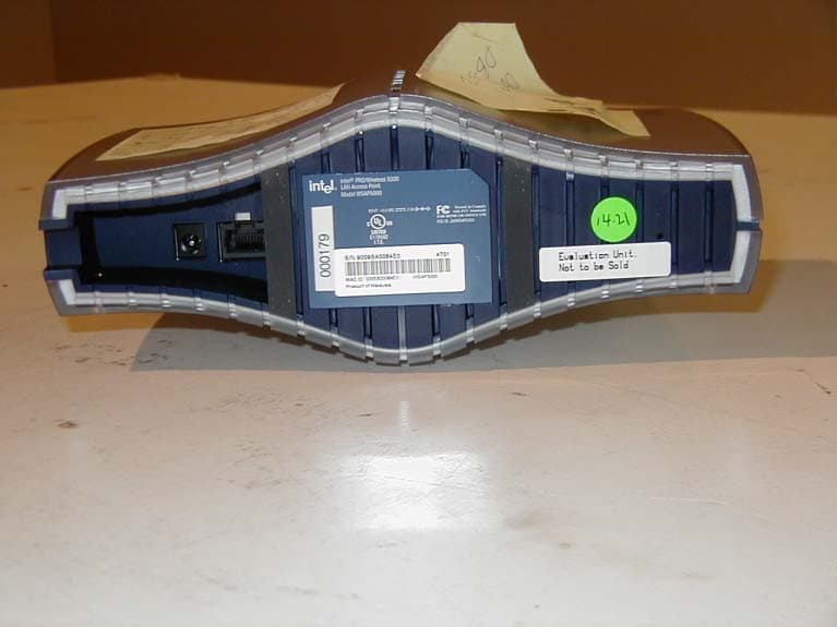
J3OWSAP2000
Jun 09, 2002WLAN Accesspoint
Equipment Class
DSS - Part 15 Spread Spectrum Transmitter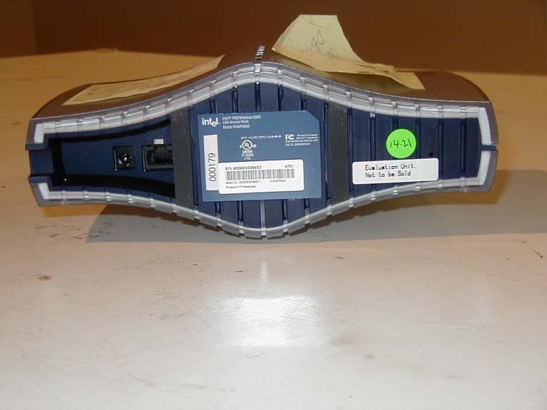
J3OWDAP5000
May 28, 2002LAN Access Point
Equipment Class
DSS - Part 15 Spread Spectrum Transmitter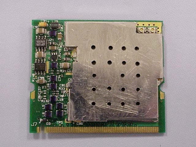
J3OWM3A5000
May 23, 2002Mini PCI Card
Equipment Class
NII - Unlicensed National Information Infrastructure TX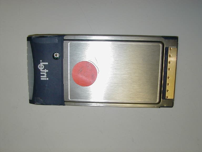
J3OWCB5000A
Apr 18, 2002Intel PRO/ Wireless 5000 Cardbus Adapter
Equipment Class
NII - Unlicensed National Information Infrastructure TX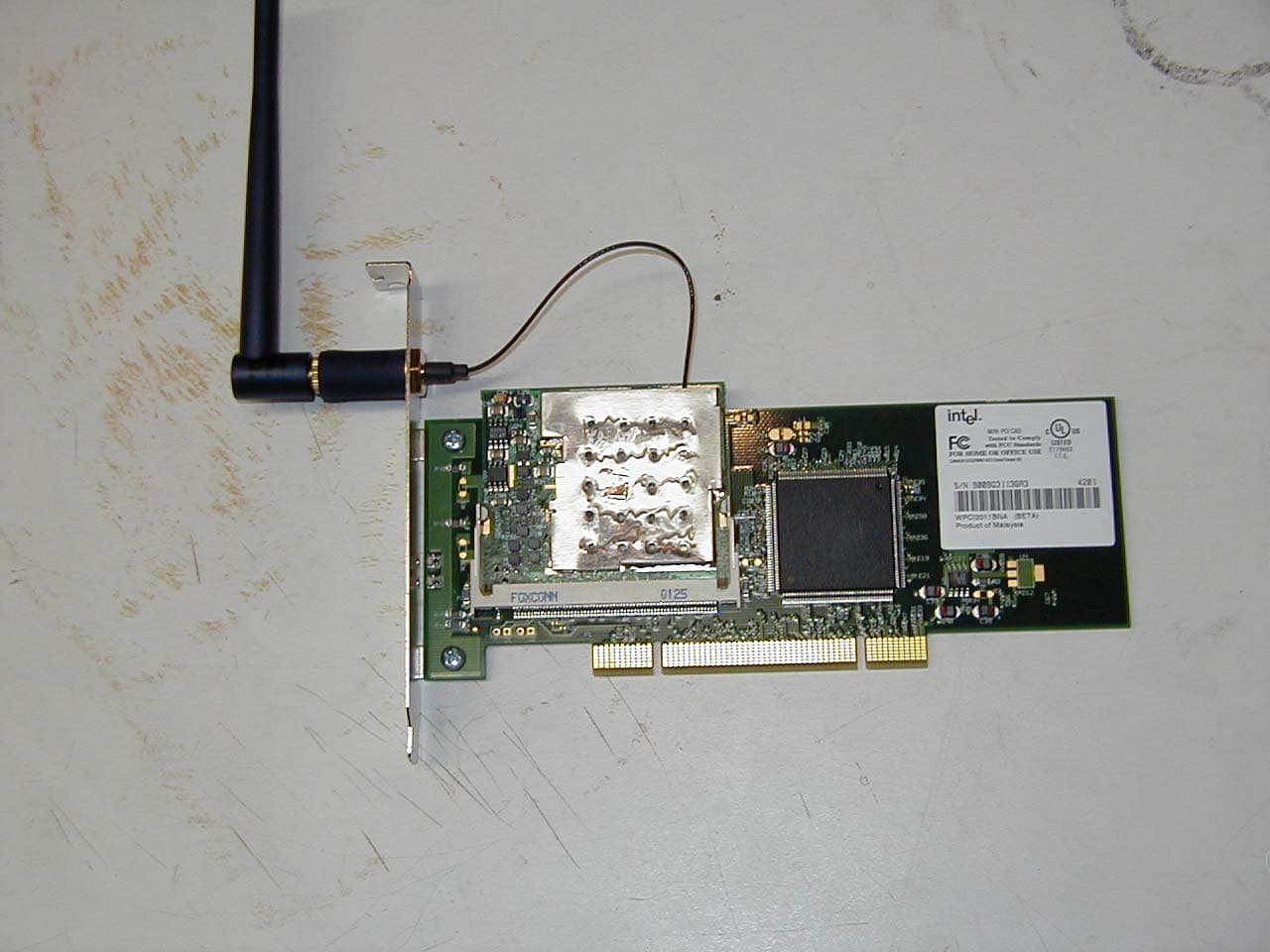
J3OWPCI5000
Mar 26, 2002Wreless PCI Adapter
Equipment Class
NII - Unlicensed National Information Infrastructure TX