J69303MICAO.O.K. Transmitter
Indyme Solutions, LLC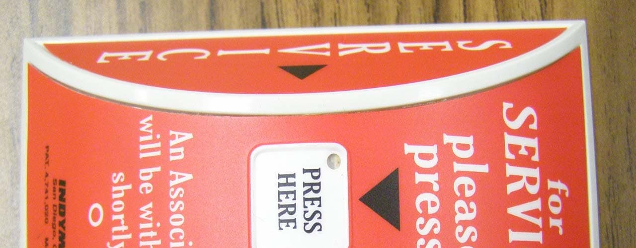
Click to zoom
Application Details
- Equipment Class
- DSC - Part 15 Security/Remote Control Transmitter
- Date of Grant
- Nov 02, 2011
- Application Purpose
- Original Equipment
- Date of Application
- Nov 02, 2011
- Equipment Note
- O.O.K. Transmitter
- Frequency Range
- 303.80000000 - 303.80000000
- Company
- Indyme Solutions, LLC
- Country
- United States
Documents & Files
Document Text
Text extracted from the exhibit documents filed with the FCC. Open a document above to read the original.
Users Manual
Technical Document CB440/511 Programming and Install Instructions 1 P/N: 430223-00 Rev R CB440/511 Programming and Installation Instructions Determine individual call box addresses prior to starting the installations. Un-programmed call boxes default to address 001 (Alarm Code-1). Triggering a call box at this address may trigger an advisory message or no action at all. Programming the CB440/CB511 Call Box Address 1. Set the internal programming jumpers for Address Programming: Address Programming Mode Programming Disable Programming CB440 JP1 OFF ON ON CB511 JP2 OFF ON OFF HELP = “PRESS HERE” RESET = “small white circle” 2. Press and hold RESET until the LED flashes one time. (approximately 8-seconds). The unit is now in address programming mode. 3. The HELP and RESET buttons are used to program the 3-digit address. Leading zeros are required. HELP = digits 1-9, RESET = digit 0 and SAVE. 4. For example, program Alarm-802 as follows: • Press HELP 8-times, RESET once to save. (8) • Press RESET once to represent the zero. (0) • Press HELP 2-times, RESET once to save. (2) Note: The LED will flash with each press of the HELP button. When the RESET button is pressed to save the 3 rd digit, the LED will flash to indicate the address that was entered. The LED will indicate digit zero by a long flash. (approximately 1-sec.) 5. Program each call box according to the mounting location. 6. Set the jumpers to “Disable” to prevent accidental changes and install the call box module. JP1JP2 CB440/511 PCA NOTE: In both Address and Mode programming, if no buttons are pressed for 30 seconds, the unit will timeout and return to normal operating mode. The LED will flash five times upon exit of either mode and any changes made will be lost. Technical Document CB440/511 Programming and Install Instructions 2 P/N: 430223-00 Rev R Mode Summary The new Call Box PCA has several different operating modes. For normal installation, each call box is programmed to mode-1 at the factory. (Standard Call Box with 8 minute LED timeout) If it becomes necessary to re-program the call box, please contact Indyme Support at 800-829-6141 for additional programming information. Location Considerations Call boxes are typically located at cash registers, service counters or other areas in which customers require assistance. Stores and installers should be aware of the Americans with Disabilities Act (ADA) requirements (48” height to the HELP button) for accessibility. Call boxes use a low powered transmitter, and operate best with a clear line of sight to the nearest receiver. Tall shelving, merchandise and metal signs can block or reduce the call box signal. Install the Call Box 1. Verify call box placement with the Store Manager and according to provided instructions. Determine the appropriate mounting hardware and location. • To mount the call box to a glass display case, affix the double-sided foam tape to the back panel of the call box. • To mount the call box to the wall, affix the Velcro tape to the back panel of the call box. • To mount the call box to a wood surface, open the call box and use the included hardware to secure the call box to the wooden surface. (CB440 only) 2. From the final mounting location, press the HELP button on the call box and verify the appropriate message is broadcast over the desired output device. FCC Notice of Compliance This device complies with Part 15 of the FCC Rules. Operation is subject to the following two conditions: (1) this device may not cause harmful interference, and (2) this device must accept any interference received, including interference that may cause undesired operation. The user is cautioned that changes or modifications not expressly approved by the party responsible for compliance could void the user’s authority to operate this equipment. This device complies with Industry Canada licence-exempt RSS standard(s). Le présent appareil est conforme aux CNR d'Industrie Canada applicables aux appareils radio exempts de licence. L'exploitation est autorisée aux deux conditions suivantes : (1) l'appareil ne doit pas produire de brouillage, et (2) l'utilisateur de l'appareil doit accepter tout brouillage radioélectrique subi, même si le brouillage est susceptible d'en compromettre le fonctionnement. Class B statement: This equipment has been tested and found to comply with the limits for a Class B digital device, pursuant to part 15 of the FCC Rules. These limits are designed to provide reasonable protection against harmful interference in a residential installation. This equipment generates, uses and can radiate radio frequency energy and, if not installed and used in accordance with the instructions, may cause harmful interference to radio communications. However, there is no guarantee that interference will not occur in a particular installation. If this equipment does cause harmful interference to radio or television reception, which can be determined by turning the equipment off and on, the user is encouraged to try to correct the interference by one or more of the following measures: —Reorient or relocate the receiving antenna. —Increase the separation between the equipment and receiver. —Connect the equipment into an outlet on a circuit different from that to which the receiver is connected. —Consult the dealer or an ex perienced radio/TV technician for help.
Cover Letter(s)
1 Mike Christensen From: Josh Hansen [[email protected]] Sent: Friday, September 23, 2011 2:42 PM To: 'Mike Christensen' Subject: RE: FCC ID: J69303MICA Attachments: 3_FCC-Label (Updated V2).PDF; 6_Users-Manual (Updated).pdf; 5_schematics (Updated).pdf; 3 _FCC-Label Location (Updated V2).pdf; D10307P1.pdf 1) See attached 2) See attached 3) See attached 4) See attached 5) See attached Josh Hansen Lab Manager (Lake Forest) Compatible Electronics, Inc. From: Mike Christensen [mailto:[email protected]] Sent: Monday, September 12, 2011 11:35 AM To: 'Josh Hansen' Subject: FCC ID: J69303MICA Mr. Hansen: In order for processing of this certification application (FCC ID: J69303MICA) to continue, the following issue(s) will have to be addressed: 1) Please provide another sample label. The statement on the label is not correct. 2) Please provide a new diagram or photo showing the location of the FCC label. The one provided is not clear enough. 3) Please provide correct schematics. The schematics provided do not have values for all components and some components have an incorrect value when compared to the internal photos. 4) Please provide a correct user manual. The user manual provided does not include the correct statements. 5) Please provide a complete test report. The test report submitted does not contain enough information regarding the duty cycle. The item(s) indicated above must be submitted before processing can continue on the above referenced application. Failure to provide the requested information within 60 days of the original e-mail date may result in application dismissal and forfeiture of the filing fee. Also, please note that partial responses increase processing time and should not be submitted. Please upload responses and/or exhibits to the electronic filing website. Your correspondence number is FCC ID: J69303MICA-1. Best Regards, 2 Mike Christensen Evaluator Compatible Electronics TCB Phone: 714-579-0500 Fax: 714-579-1850 www.celectronics.com "Follow our EMC and Regulatory Compliance blog at http://feeds.feedburner.com/EMCnews"
ID Label/Location Info
2 x .75 Inches, White Vinyl, Black Print Material: RF T -4911 Overlaminate: 1mil Clear Polypropylene, RL-TCC-UL2000 or QS800XC Adhesive: TS523 All materials and finishes shall comply with European Union restrictions of hazardous substances. (RoHS) Alternate materials must have RoHS compliance and be approved by Indyme. For art detail reference Indyme control document PS file: Minimum Radius .075" 220198-19_D CB440 Label.eps REVISIONS REV.DESCRIPTIONDATEAPPROVED ARelease to Manufacture4/13/11Greg K B Text Added to Label5/13/11Greg K C Added FCC 2-part Statemnet Channged Label size 8/1/11Greg K DCorrect 2 Part Statement9/14/11Greg K .X .XX .XXX ±.125 ±.025 ±.005 ± 0.5 º 8/1/11 MFG APPR ENG APPR DRAWN APPROVALSDATE CHECKED COMMENTS INTERPRET GEOMETRIC TOL PER: ASME Y14.100 - 2000 Label, FCC/CE, CB440 8/1/11 White Vinyl RF T-4911 220198-19 D FILE NAME: 220198-19_D CB440 Label Sheet 1 of 1 UNLESS OTHERWISE SPECIFIED DIMENSION TOLERANCES ARE DECIMAL: in: ANGLES: FINISH MATERIAL A SCALE REV DWG NO. CAGE CODE SIZE THIS DOCUMENT IS THE PROPERTY OF INDYME AND IS CONSIDERED COMPANY CONFIDENTIAL. THE REPRODUCTION OR USE OF INFORMATION HEREIN, ALL OR IN PART, IS EXPRESSLY PROHIBITED WITHOUT WRITTEN CONFIRMATION FROM A PRINCIPAL MEMBER OF MANAGEMENT AT INDYME. 4:1 4:1 indyme Solutions 8/1/11 Greg K Larry O G King
Test Report
Report Number: D10307P1 FCC Part 15 Subpart C Section 15.231 Test Report Shopper Call Box - FCC ID: J69303MICA Model: CB440 Brea Division 114 Olinda Drive Brea, CA 92823 (714) 579-0500 Agoura Division 2337 Troutdale Drive Agoura, CA 91301 (818) 597-0600 Silverado Division 19121 El Toro Road Silverado, CA 92676 (949) 589-0700 Lake Forest Division 20621 Pascal Way Lake Forest, CA 92630 (949) 587-0400 Page 1 of 16 FCC PART 15, SUBPART B and SUBPART C TEST REPORT for SHOPPER CALL BOX MODEL: CB440 Prepared for INDYME SOLUTIONS, INC. 8295 AERO PLACE SAN DIEGO, CA 92123 Prepared by:_____________________ JOEY MADLANGBAYAN Approved by:____________________ JOSH HANSEN COMPATIBLE ELECTRONICS INC. 20621 Pascal Way LAKE FOREST, CA 92630 (949) 587-0400 DATE: MARCH 17, 2011 REPORT APPENDICES TOTAL BODY A B C D E PAGES 16 2 2 2 7 17 45 This report shall not be reproduced except in full, without the written approval of Compatible Electronics. Report Number: D10307P1 FCC Part 15 Subpart C Section 15.231 Test Report Shopper Call Box - FCC ID: J69303MICA Model: CB440 Brea Division 114 Olinda Drive Brea, CA 92823 (714) 579-0500 Agoura Division 2337 Troutdale Drive Agoura, CA 91301 (818) 597-0600 Silverado Division 19121 El Toro Road Silverado, CA 92676 (949) 589-0700 Lake Forest Division 20621 Pascal Way Lake Forest, CA 92630 (949) 587-0400 Page 2 of 16 TABLE OF CONTENTS Section / Title PAGE GENERAL REPORT SUMMARY 4 SUMMARY OF TEST RESULTS 4 1. PURPOSE 5 2. ADMINISTRATIVE DATA 6 2.1 Location of Testing 6 2.2 Traceability Statement 6 2.3 Cognizant Personnel 6 2.4 Date Test Sample was Received 6 2.5 Disposition of the Test Sample 6 2.6 Abbreviations and Acronyms 6 3. APPLICABLE DOCUMENTS 7 4. DESCRIPTION OF TEST CONFIGURATION 8 4.1 Description Of Test Configuration - EMI 8 4.1.1 Cable Construction and Termination 9 5. LISTS OF EUT, ACCESSORIES AND TEST EQUIPMENT 10 5.1 EUT and Accessory List 10 5.2 EMI Test Equipment 11 6. TEST SITE DESCRIPTION 12 6.1 Test Facility Description 12 6.2 EUT Mounting, Bonding and Grounding 12 7. TEST PROCEDURES 13 7.1 RF Emissions 13 7.1.1 Conducted Emissions Test 13 7.1.2 Radiated Emissions (Spurious and Harmonics) Test 14 7.1.3 Radiated Emissions (Spurious and Harmonics) Test (Continued) 15 7.1.4 Peak radiated EMI 15 7.1.5 Bandwidth of the Fundamental 15 8. CONCLUSIONS 16 Report Number: D10307P1 FCC Part 15 Subpart C Section 15.231 Test Report Shopper Call Box - FCC ID: J69303MICA Model: CB440 Brea Division 114 Olinda Drive Brea, CA 92823 (714) 579-0500 Agoura Division 2337 Troutdale Drive Agoura, CA 91301 (818) 597-0600 Silverado Division 19121 El Toro Road Silverado, CA 92676 (949) 589-0700 Lake Forest Division 20621 Pascal Way Lake Forest, CA 92630 (949) 587-0400 Page 3 of 16 LIST OF APPENDICES APPENDIX TITLE A Laboratory Recognitions B Modifications to the EUT C Additional Models Covered Under This Report D Diagrams, Charts, and Photos Test Setup Diagrams Radiated Emissions Photos Antenna and Effective Gain Factors E Data Sheets LIST OF FIGURES FIGURE TITLE 1 Plot Map And Layout of 3 Meter Radiated Site Report Number: D10307P1 FCC Part 15 Subpart C Section 15.231 Test Report Shopper Call Box - FCC ID: J69303MICA Model: CB440 Brea Division 114 Olinda Drive Brea, CA 92823 (714) 579-0500 Agoura Division 2337 Troutdale Drive Agoura, CA 91301 (818) 597-0600 Silverado Division 19121 El Toro Road Silverado, CA 92676 (949) 589-0700 Lake Forest Division 20621 Pascal Way Lake Forest, CA 92630 (949) 587-0400 Page 4 of 16 GENERAL REPORT SUMMARY This electromagnetic emission test report is generated by Compatible Electronics Inc., which is an independent testing and consulting firm. The test report is based on testing performed by Compatible Electronics personnel according to the measurement procedures described in the test specifications given below and in the "Test Procedures" section of this report. The measurement data and conclusions appearing herein relate only to the sample tested and this report may not be reproduced without the written permission of Compatible Electronics, unless done so in full. This report must not be used to claim product endorsement by NVLAP, NIST or any other agency of the U.S. Government. Device Tested: Shopper Call Box Model: CB440 Product Description: See Expository Statement Modifications: The EUT was not modified. Manufacturer: Indyme Solutions, Inc. 9085 Aero Drive San Diego, CA 92123 Test Date: March 7, 2011 Test Specifications: CFR Title 47, Part 15 Subpart C, Sections 15.205, 15.209 and 15.231 Test Procedure: ANSI C63.10: 2009 Test Deviations: The test procedure was not deviated from during the testing. SUMMARY OF TEST RESULTS TEST DESCRIPTION RESULTS 1 Radiated RF Emissions, 0.01 - 30MHz Complies with the limits of CFR Title 47, Part 15, Subpart C, section 15.205 & 15.209 2 Radiated RF Emissions, 30 - 4000 MHz Complies with the limits of CFR Title 47, Part 15, Subpart C, section 15.205 & 15.209 3 -20 dB Occupied Bandwidth of the Emission Complies with the limits of CFR Title 47, Part 15, Subpart C, section 15.231 (c). 4 Peak Radiated EMI Complies with the limits of CFR Title 47, Part 15, Subpart C, section 15.231 (b). Report Number: D10307P1 FCC Part 15 Subpart C Section 15.231 Test Report Shopper Call Box - FCC ID: J69303MICA Model: CB440 Brea Division 114 Olinda Drive Brea, CA 92823 (714) 579-0500 Agoura Division 2337 Troutdale Drive Agoura, CA 91301 (818) 597-0600 Silverado Division 19121 El Toro Road Silverado, CA 92676 (949) 589-0700 Lake Forest Division 20621 Pascal Way Lake Forest, CA 92630 (949) 587-0400 Page 5 of 16 1. PURPOSE This document is a qualification test report based on the Electromagnetic Interference (EMI) tests performed on the Shopper Call Box Model: CB440. The EMI measurements were performed according to the measurement procedure described in ANSI C63.10. The tests were performed in order to determine whether the electromagnetic emissions from the equipment under test, referred to as EUT hereafter, are within the spec…
Text truncated - open the document above for the full version.
Contact Information
Applicant
William Kepner(COO and VP of Engineering)
Technical Contact
Compatible Electronics, Inc.Kyle Fujimoto
[email protected]714-579-0500
114 Olinda Drive · Brea, California · United States
Test Firm
Compatible Electronics, Inc.Michael Christensen
Technical Specifications
| # | Rule Parts | Frequency Range | Power Output |
|---|---|---|---|
| 1 | 15.231 | 303.8 MHz - 303.8 MHz | - |
Other Applications from Indyme Solutions, LLC
J69CB526
Jan 17, 2014Shopper Call Box
Equipment Class
DSC - Part 15 Security/Remote Control Transmitter
J69TYPEB
Sep 18, 2013Wireless Help Button
Equipment Class
DSS - Part 15 Spread Spectrum Transmitter
J69CB461
Mar 26, 2013Wireless Help Button
Equipment Class
DSC - Part 15 Security/Remote Control Transmitter
J69TYPEA2
Mar 12, 2013Help Button
Equipment Class
DSS - Part 15 Spread Spectrum TransmitterJ69CB529A
Apr 29, 2012Director Call Box
Equipment Class
DSC - Part 15 Security/Remote Control Transmitter