J69TYPEBWireless Help Button
Indyme Solutions, LLC
Click to zoom
Application Details
- Equipment Class
- DSS - Part 15 Spread Spectrum Transmitter
- Date of Grant
- Sep 18, 2013
- Application Purpose
- Original Equipment
- Date of Application
- Sep 17, 2013
- Equipment Note
- Wireless Help Button
- Frequency Range
- 918.10000000 - 923.00000000
- Company
- Indyme Solutions, LLC
- Country
- United States
Documents & Files
Document Text
Text extracted from the exhibit documents filed with the FCC. Open a document above to read the original.
Users Manual
Technical Document 430708-00 Rev. H Indyme Solutions, Inc. 8295 Aero Place San Diego, CA 92123 USA +1.858.268.0717 +1.800.829.6141Page 1 of 5 CB938 Wireless Help Button Programming and Installation Instructions Overview The CB938 is a member of the Global Solutions Family. Indyme GSF products operate in the 800MHz – 900MHz frequency spectrum. The CB938 is a 1-button, GSF Help button designed for use at Customer Service locations. GSF Help buttons are designed to communicate with a GSF Access Point. GSF products are not compatible with legacy devices Programming Parameters GSF products MUST be properly programmed to establish communication. Programming parameters MUST match your configuration. The default settings are for testing purposes only and should not be used. Failure to properly program your help button and access point will prevent your devices from working. GSF Help buttons have three primary programming parameters; Netcode, Address and Operating Mode. These MUST be programmed in the correct order to establish communication and ensure proper operation. Identify the parameters for your configuration before you begin programming. Using the programming instructions below set the following parameters in order. Netcode – unique identification code for the installation environment. Address – alarm number associated with a control unit alarm event. Operating Mode – defines how the help button will respond when activated. Programming a help button requires a series of button presses. The specific buttons vary by device type. On the CB938, SET is the “Press Here” button and RESET is a small circle near the bottom of the call box. The assurance LED is red and is located above the SET button. This LED will flash during programming to indicate your progress. Netcode *00000001 Address *0001 Operating Mode *1 * Default parameters are for testing purposes only. CB938 RESET LED Technical Document 430708-00 Rev. H Indyme Solutions, Inc. 8295 Aero Place San Diego, CA 92123 USA +1.858.268.0717 +1.800.829.6141Page 2 of 5 GSF Help button Programming GSF Help buttons function in the 800MHz – 900MHz frequency spectrum. These wireless transceivers, communicate with the CB951 Access Point. Each help button MUST be programmed with the correct parameters to match the CB951 Access Point(s). Help buttons use a hierarchy based menu structure. You must enter the Programming Menu first, to select the desired submenu. Each submenu may have one or more options available. These options are used to assign specific operational characteristics to the help button. Review the submenus/options before you begin programming. The submenus/options will vary by model. Enter the Programming Menu Press and hold the RESET button until the assurance LED flashes one time. Press and hold the SET button, until the assurance LED flashes two times. Press and hold the RESET button, until the assurance LED flashes three times. The help button is now in the Programming Menu mode, proceed to the desired submenu. (***) Menu-1: Address Programming Assigns the help button to a corresponding alarm event programmed in the control unit. A help button address is a four digit number from 0001 to 4095. Leading zeros are required. After entering the Programming Menu; Press the SET button one time for Menu-1, RESET once to save. The assurance LED will flash one time to indicate Menu-1 was selected. Use SET and RESET to program the 4-digit address as follows; SET = digits 1-9, RESET = digit 0 and SAVE. Leading zeros are required For example, program Alarm-0802 as follows: Press RESET once to represent the zero. (0) Press SET eight times, RESET once to save. (8) Press RESET once to represent the zero. (0) Press SET two times, RESET once to save. (2) Note: When the RESET button is pressed to save the 4 th digit, the assurance LED will flash to indicate the address that was entered. The assurance LED will indicate digit zero by a long flash. (approximately 1-sec.) Programming Menu Address Learn Operation Clone Menu-1 Menu-2 Menu-3 Menu-7 Technical Document 430708-00 Rev. H Indyme Solutions, Inc. 8295 Aero Place San Diego, CA 92123 USA +1.858.268.0717 +1.800.829.6141Page 3 of 5 Menu-2: Learn Mode Allows the help button to capture the Netcode from another GSF device; (help button or access point). All help buttons and access points must have the same Netcode to communicate. After entering the Programming Menu; Press the SET button two times for Menu-2, RESET once to save. The LED will flash twice to indicate Menu-2 was selected. The LED will then begin flashing. ¼ second on, 1 second off. This indicates that the help button is requesting a Netcode. When the help button receives a Netcode, it will flash the assurance LED rapidly for approximately 3 seconds and then it will exit Menu-2. If no Netcode is received within 5 minutes, the help button will exit Menu-2. Menu-3: Operating Mode Assigns the help button operating characteristics; timeout duration, RESET signal and number of active buttons. Although set at the help button, the Operating Mode can be reset and overridden by the control unit. Operating Modes will vary by help button type, below are the default modes for this help button. After entering the Programming Menu; Press the SET button three times for Menu-3, RESET once to save. The assurance LED will flash three times to indicate Menu-3 was selected. Press the SET button to select a Help button Operating Mode: <1, 2, >, RESET once to save. The assurance LED will flash to indicate the selected Operating Mode. Mode 1 - Standard 8-min timeout, No Reset Press any channel button to trigger the alarm state; the corresponding LED(s) will flash. The LED will flash for 8 minutes, then extinguish with no reset sent. The RESET button will sent a reset signal for all active channels. Mode 2 - Standard 30-sec timeout, No Reset Press any channel button to trigger the alarm state; the corresponding LED(s) will flash. The L…
Text truncated - open the document above for the full version.
Users Manual
Technical Document 430710-00 Rev. H Indyme Solutions, Inc. 8295 Aero Place San Diego, CA 92123 U +1.858.268.0717 +1.800.829.6141 Page 1 of 5 CB982 Wireless Help button Programming and Installation Instructions Overview The CB982 is a member of the Global Solutions Family. Indyme GSF products operate in the 800MHz – 900MHz frequency spectrum. The CB982 is a 1-button, GSF Help button designed for use at Customer Service locations. GSF Help buttons are designed to communicate with a GSF Access Point. GSF products are not compatible with legacy devices Programming Parameters GSF products MUST be properly programmed to establish communication. Programming parameters MUST match your configuration. The default settings are for testing purposes only and should not be used. Failure to properly program your help button and access point will prevent your devices from working. GSF Help buttons have three primary programming parameters; Netcode, Address and Operating Mode. These MUST be programmed in the correct order to establish communication and ensure proper operation. Identify the parameters for your configuration before you begin programming. Using the programming instructions below set the following parameters in order. Netcode – unique identification code for the installation environment. Address – alarm number associated with a control unit alarm event. Operating Mode – defines how the help button will respond when activated. Programming a help button requires a series of button presses. The specific buttons vary by help button type. On the CB982, SET is the “PRESS HERE” button and RESET is a small square below the SET button. The assurance LED is red and is located above the SET button. This LED will flash during programming to indicate your progress. Netcode *00000001 Address *0001 Operating Mode *1 * Default parameters are for testing purposes only. CB982 RESET LED Technical Document 430710-00 Rev. H Indyme Solutions, Inc. 8295 Aero Place San Diego, CA 92123 U +1.858.268.0717 +1.800.829.6141 Page 2 of 5 GSF Help button Programming GSF Help buttons function in the 800MHz – 900MHz frequency spectrum. These wireless transceivers, communicate with the CB951 Access Point. Each help button MUST be programmed with the correct parameters to match the CB951 Access Point(s). Help buttons use a hierarchy based menu structure. You must enter the Programming Menu first, to select the desired submenu. Each submenu may have one or more options available. These options are used to assign specific operational characteristics to the help button. Review the submenus/options before you begin programming. The submenus/options will vary by help button model. Enter the Programming Menu Press and hold the RESET button until the assurance LED flashes one time. Press and hold the SET button, until the assurance LED flashes two times. Press and hold the RESET button, until the assurance LED flashes three times. The help button is now in the Programming Menu mode, proceed to the desired submenu. (***) Menu-1: Address Programming Assigns the help button to a corresponding alarm event programmed in the control unit. A help button address is a four digit number from 0001 to 4095. Leading zeros are required. After entering the Programming Menu; Press the SET button one time for Menu-1, RESET once to save. The assurance LED will flash one time to indicate Menu-1 was selected. Use SET and RESET to program the 4-digit address as follows; SET = digits 1-9, RESET = digit 0 and SAVE. Leading zeros are required For example, program Alarm-0802 as follows: Press RESET once to represent the zero. (0) Press SET eight times, RESET once to save. (8) Press RESET once to represent the zero. (0) Press SET two times, RESET once to save. (2) Note: When the RESET button is pressed to save the 4 th digit, the assurance LED will flash to indicate the address that was entered. The assurance LED will indicate digit zero by a long flash. (approximately 1-sec.) Programming Menu Address Learn Operation Clone Menu-1 Menu-2 Menu-3 Menu-7 Technical Document 430710-00 Rev. H Indyme Solutions, Inc. 8295 Aero Place San Diego, CA 92123 U +1.858.268.0717 +1.800.829.6141 Page 3 of 5 Menu-2: Learn Mode Allows the help button to capture the Netcode from another GSF device; (help button or access point). All help buttons and access points must have the same Netcode to communicate. After entering the Programming Menu; Press the SET button two times for Menu-2, RESET once to save. The LED will flash twice to indicate Menu-2 was selected. The LED will then begin flashing. ¼ second on, 1 second off. This indicates that the help button is requesting a Netcode. When the help button receives a Netcode, it will flash the assurance LED rapidly for approximately 3 seconds and then it will exit Menu-2. If no Netcode is received within 5 minutes, the help button will exit Menu-2. Menu-3: Operating Mode Assigns the help button operating characteristics; timeout duration, RESET signal and number of active buttons. Although set at the help button, the Operating Mode can be reset and overridden by the control unit. Operating Modes will vary by help button type, below are the default modes for this help button. After entering the Programming Menu; Press the SET button three times for Menu-3, RESET once to save. The assurance LED will flash three times to indicate Menu-3 was selected. Press the SET button to select a Help button Operating Mode: <1, 2, >, RESET once to save. The assurance LED will flash to indicate the selected Operating Mode. Mode 1 - Standard 8-min timeout, No Reset Press any channel button to trigger the alarm state; the corresponding LED(s) will flash. The LED will flash for 8 minutes, then extinguish with no reset sent. The RESET button will sent a reset signal for all active channels. Mode 2 - Standard 30-sec timeout, No Reset Press any channel button to trigger the alarm state; the corresponding LED(s) will flash. Th…
Text truncated - open the document above for the full version.
Cover Letter(s)
May 1, 2013 Nemko 2210 Faraday Avenue Carlsbad, CA 92008 USA Attn: Director of Certification FCC ID: J69TYPEB Authority to Act as Agent On our behalf, I appoint Alan Laudani of Nemko USA Inc., 2210 Faraday Ave., Carlsbad, CA 92008 USA to act as our agent in the preparation of this application for equipment certification. I certify that submitted documents properly describe the device or system for which equipment certification is sought. I also certify that each unit manufactured, imported or marketed, as defined in the Federal Communications Commission's regulations will have affixed to it a label identical to that submitted for approval with this application. For instances where our authorized agent signs the application for certification on our behalf, I acknowledge that all responsibility for complying with the terms and conditions for certification, as specified by Nemko, still resides with lndyme Solutions, Inc., 8295 Aero Place, San Diego, CA 92123. This appointment is in effect until December 31, 2013. Sincerely, Steve Deal CEO lndyme Solutions, Inc.
Cover Letter(s)
March 25, 2013 Nemko Canada Inc. 303 River Road Ottawa, Ontario, Canada K1V 1H2 Re: Request of Confidentiality for FCC ID: J69TYPEB Pursuant to Sections 0.457(d)(l)(ii) and 0.459 of the Commission's Rules, the Applicant hereby requests confidential treatment of information accompanying as outlined below: Schematics, Parts List, Operating Description, Block Diagrams The above materials contain trade secrets and proprietary information not customarily released to the public. The public disclosure of these matters might be harmful to the Applicant and provide unjustified benefits to its competitors. The Applicant understands that pursuant to Rule 0.457(d)(l)(ii), disclosure of this Application and all accompanying documentation will not be made before the date of the Grant for this Application. . Sincerely, Steve Deal CEO lndyme Solutions, Inc.
External Photos
CB938 CB982
ID Label/Location Info
All materials and finishes shall comply with European Union restrictions of hazardous substances. (RoHS) Alternate materials must have RoHS compliance and be approved by Indyme. White Vinyl, Black Print Material: RF T -4911 Overlaminate: 1mil Clear Polypropylene, RL-TCC-UL2000 or QS800XC Adhesive: TS523 2.00 1.50 minimum radius .1" 4 plcs F 220198-12 CB938 FCC/CE/C-tick Label 6/11/09 6/11/09 6/11/09 Larry O Fred A For Art Work Reference 220198-12_F CB938 FCC.eps REVISIONS REV.DESCRIPTIONDATEAPPROVED ARelease to Manufacture6/11/09Fred A BMade Label Generic12/28/98Fred A CAdded FCC and IC ID numbers1/14/11Andrea B DCorrected FCC Statement9/21/11Andrea B EMoved Graphic Placement12/7/11Andrea B FChange Model, Added French12/19/12Andrea B 63 μIN .X .XX .XXX ±.5 ±.25 ±.013 ± 0.5 º MFG APPR ENG APPR DRAWN APPROVALSDATE CHECKED COMMENTS INTERPRET GEOMETRIC TOL PER: ASME Y14.100 - 2000 Sheet1 OF 1 UNLESS OTHERWISE SPECIFIED DIMENSION TOLERANCES ARE DECIMAL: INCHES: ANGLES: FINISH MATERIAL A SCALE REV DWG NO. CAGE CODE SIZE THIS DOCUMENT IS THE PROPERTY OF INDYME AND IS CONSIDERED COMPANY CONFIDENTIAL. THE REPRODUCTION OR USE OF INFORMATION HEREIN, ALL OR IN PART, IS EXPRESSLY PROHIBITED WITHOUT WRITTEN CONFIRMATION FROM A PRINCIPAL MEMBER OF MANAGEMENT AT INDYME. 2:1 indyme Solutions G King CB938 0 All materials and finishes shall comply with European Union restrictions of hazardous substances. (RoHS) Alternate materials must have RoHS compliance and be approved by Indyme. White Vinyl, Black Print Material: RF T -4911 Overlaminate: 1mil Clear Polypropylene, RL-TCC-UL2000 or QS800XC Adhesive: TS523 2.00 1.50 minimum radius .1" 4 plcs A 220198-32 CB982 FCC/CE/C-tick Label For Art Work Reference 220198-32_A CB982 FCC.eps REVISIONS REV.DESCRIPTIONDATEAPPROVED ARelease to Manufacture12/19/12Andrea B 63 μIN .X .XX .XXX ±.5 ±.25 ±.013 ± 0.5 º MFG APPR ENG APPR DRAWN APPROVALSDATE CHECKED COMMENTS INTERPRET GEOMETRIC TOL PER: ASME Y14.100 - 2000 Sheet1 OF 1 UNLESS OTHERWISE SPECIFIED DIMENSION TOLERANCES ARE DECIMAL: INCHES: ANGLES: FINISH MATERIAL A SCALE REV DWG NO. CAGE CODE SIZE THIS DOCUMENT IS THE PROPERTY OF INDYME AND IS CONSIDERED COMPANY CONFIDENTIAL. THE REPRODUCTION OR USE OF INFORMATION HEREIN, ALL OR IN PART, IS EXPRESSLY PROHIBITED WITHOUT WRITTEN CONFIRMATION FROM A PRINCIPAL MEMBER OF MANAGEMENT AT INDYME. 2:1 indyme Solutions Noah K Greg K Andrea B 12/19/12 12/19/12 12/19/12 CB982
Internal Photos
Type B PCA family CB938 CB982
RF Exposure Info
MPE S = power density P = power input to the antenna G = antenna gain R = distance Conducted output power:10.0(dBm) Tune up tolerance1(dB) Number of carriers1(N) 13(mW) 0.013(W) Antenna gain:1.282(dBi) Maximum antenna gain:1.34(numeric) EIRP0.017(W) ERP0.010(W) Distance:20(cm) Duty Cycle:100(%) Frequency:918.1(MHz) MPE Limit:0.612(mW/cm^2) Power density:0.00336(mW/cm^2) 0.0336(W/m^2) Margin22.6(dB) 2 4R PG S p =
Test Report
Nemko USA, Inc. 2210 Faraday Ave, Suite 150 Carlsbad, CA 92008 Phone (760) 444-3500 Fax (760) 444-3005 FCC Part 15 Subpart C, 15.247 : 05/08/2013 CERTIFICATION TEST REPORT Applicant: INDYME SOLUTIONS, INC. 8295 AERO PLACE San Diego, CA 92123 Equipment Under Test (EUT): Type B Wireless Call Box Model: CB938, CB982 FCC ID: J69TYPEB IC: 1809A-TYPEB In Accordance With: FCC Part 15 Subpart C, 15.247 IC RSS-210 Issue 8 December 2010 IC RSS-Gen Issue 3 December 2010 Authorized By: Nemko USA Inc. 2210 Faraday Street, Suite 150 Carlsbad, CA 92008 Tested By: A. LAUDANI, EMC/RF Test Engineer Date: M AY 13, 2013 Report Number: 2013 05224475 FCC Project Number: Q10228463 Nex Number: 224475 Total Number of Pages: 23 Nemko USA, Inc. 2210 Faraday Street, Suite 150, Carlsbad, CA 92008 Phone (760) 444-3500 Fax (760) 444-3005 IC: 1809A-TYPEB Report Number: 2013 05224475 FCC FCC ID: J69TYPEB Specification: FCC Part 15 Subpart C, 15.247 Page 2 of 23 1. Applicant Affirmation Steve Deal representing Indyme Solutions, Inc. hereby affirms: a) That he/she has reviewed and concurs that the test shown in this report are reflective of the operational characteristics of the device for which certification is sought; b) That the device in this test report will be representative of production units; c) That all changes (in hardware and software/firmware) to the subject device will be reviewed. d) That any changes impacting the attributes, functionality or operational characteristics documented in this report will be communicated to the body responsible for approving (certifying) the subject equipment. Steve Deal, CEO Date: December 6, 2012 8295 Aero Place San Diego, CA 92123 Address 858-707-8525 [email protected] Telephone number Email address of official NOTE—This affirmation must be signed by the responsible party before it is submitted to a regulatory body for approval. Nemko USA, Inc. 2210 Faraday Street, Suite 150, Carlsbad, CA 92008 Phone (760) 444-3500 Fax (760) 444-3005 IC: 1809A-TYPEB Report Number: 2013 05224475 FCC FCC ID: J69TYPEB Specification: FCC Part 15 Subpart C, 15.247 Page 3 of 23 Section 1. Summary of Test Results 1.1 General All measurements are traceable to national standards These tests were conducted on a sample of the equipment for the purpose of demonstrating compliance with Part 15; Subpart C and RSS-210, Issue 8 December 2010. Radiated tests were conducted is accordance with ANSI C63.4-2003. Radiated emissions are made in the 10m anechoic chamber. A description of the test facility is on file with the FCC and IC. The assessment summary is as follows: Apparatus Assessed: CB938, CB982 Specifications: FCC Part 15 Subpart C, 15.247 IC RSS-210 Issue 8 December 2010 IC RSS 210 (Issue 8, December 2010) Annex 8 Date Received in Laboratory: N OVEMBER 6, 2012 Compliance Status: Complies Exclusions: None Non-compliances: None Nemko USA, Inc. 2210 Faraday Street, Suite 150, Carlsbad, CA 92008 Phone (760) 444-3500 Fax (760) 444-3005 IC: 1809A-TYPEB Report Number: 2013 05224475 FCC FCC ID: J69TYPEB Specification: FCC Part 15 Subpart C, 15.247 Page 4 of 23 1.2 Report Release History: REVISION DATE COMMENTS - May 13, 2013 Prepared By: A. Laudani - May 13, 2013 Initial Release: Alan Laudani Note that the results contained in this report relate only to the items tested and were obtained in the period between the date of initial receipt of samples and the date of issue of the report. This test report has been completed in accordance with the requirements of ISO/IEC 17025. Nemko USA Inc. authorizes the applicant to reproduce this report provided it is reproduced in its entirety and for use by the company’s employees only. Any use which a third party makes of this report, or any reliance on or decisions to be made based on it, are the responsibility of such third parties. Nemko USA Inc. accepts no responsibility for damages, if any, suffered by any third party as a result of decisions made or actions based on this report. TESTED BY: Date: May 13, 2013 Alan Laudani, EMC Engineer Nemko USA, Inc. 2210 Faraday Street, Suite 150, Carlsbad, CA 92008 Phone (760) 444-3500 Fax (760) 444-3005 IC: 1809A-TYPEB Report Number: 2013 05224475 FCC FCC ID: J69TYPEB Specification: FCC Part 15 Subpart C, 15.247 Page 5 of 23 TABLE OF CONTENTS 1. Applicant Affirmation ............................................................................................. 2 Section 1. Summary of Test Results ........................................................................... 3 1.1 General ........................................................................................................................................ 3 1.2 Report Release History: ............................................................................................................... 4 Section 2: Equipment Under Test ................................................................................... 6 2.1 Product Identification ................................................................................................................... 6 2.2 Theory of Operation ..................................................................................................................... 6 2.3 Technical Specifications of the EUT ............................................................................................ 6 Section 3: Test Conditions .............................................................................................. 7 3.1 Specifications ............................................................................................................................... 7 3.3 Test Environment ......................................................................................................................... 7 3.4 Test Equipment ............................................................................................................................ 7 Section 4: Observations .......................................................…
Text truncated - open the document above for the full version.
Test Setup Photos
Nemko USA, Inc. 2210 Faraday Avenue, Suite 150 Carlsbad, CA 92008 Phone: (760) 444‐3500 Fax: (760) 444‐3005 1 Radiated Field Strength Spurious Emission Test Setup 2 Occupied Bandwidth Test Setup
Contact Information
Applicant
William Kepner(COO and VP of Engineering)
Technical Contact
Indyme Solutions, IncGreg King
[email protected]858-707-8531
8295 Aero Place · San Diego, California · United States
Non-Technical Contact
Indyme Solutions, Inc.Andrea Braxton
[email protected]858-268-0717
Test Firm
Nemko USA, Inc. - San Diego EMC DivisionJan Blomgren
[email protected]760-444-3500
Technical Specifications
| # | Rule Parts | Frequency Range | Power Output |
|---|---|---|---|
| 1 | 15C | 918.1 MHz - 923 MHz | 8.00 mW |
Other Applications from Indyme Solutions, LLC
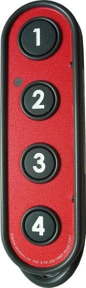
J69CB526
Jan 17, 2014Shopper Call Box
Equipment Class
DSC - Part 15 Security/Remote Control Transmitter
J69CB461
Mar 26, 2013Wireless Help Button
Equipment Class
DSC - Part 15 Security/Remote Control Transmitter
J69TYPEA2
Mar 12, 2013Help Button
Equipment Class
DSS - Part 15 Spread Spectrum TransmitterJ69CB529A
Apr 29, 2012Director Call Box
Equipment Class
DSC - Part 15 Security/Remote Control TransmitterJ69CB430
Apr 23, 2012Call Button
Equipment Class
DSC - Part 15 Security/Remote Control Transmitter