J69CB550Wireless Director Call Box
Indyme Solutions, LLC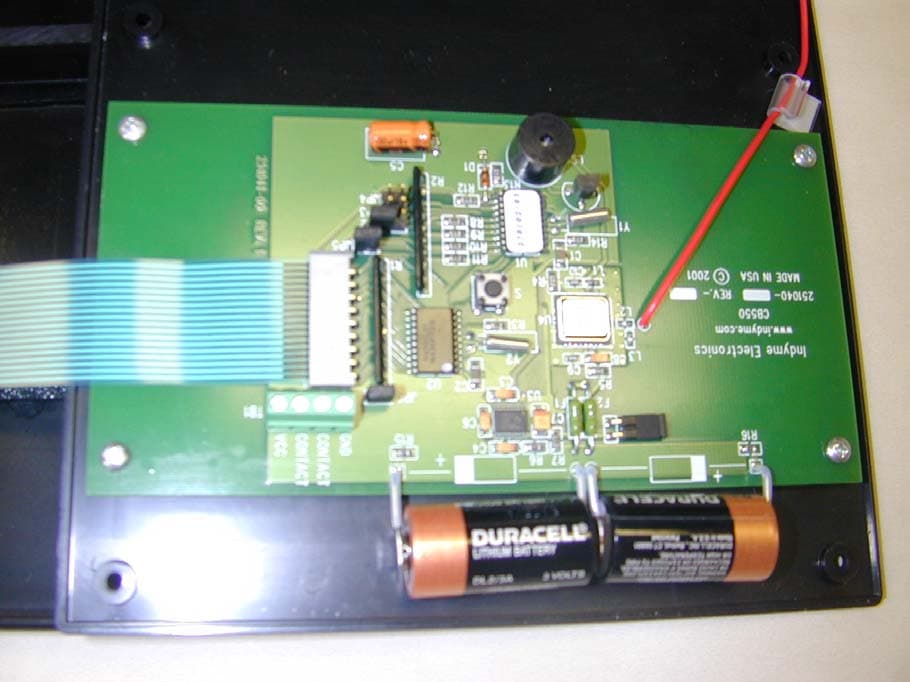
Click to zoom
Application Details
- Equipment Class
- DXX - Part 15 Low Power Communication Device Transmitter
- Date of Grant
- Jul 25, 2002
- Application Purpose
- Original Equipment
- Date of Application
- Jul 25, 2002
- Equipment Note
- Wireless Director Call Box
- Frequency Range
- 303.80000000 - 303.80000000
- Company
- Indyme Solutions, LLC
- Country
- United States
Documents & Files
Document Text
Text extracted from the exhibit documents filed with the FCC. Open a document above to read the original.
Users Manual
Technical Document CB550 Customer Survey Call Box INSTALLATION AND PROGRAMMING PROCEDURE Scope This document covers all the necessary instructions for installing the CB550 Customer Survey Call Box and how to program the call box using the Status LEDs indicators. The Status LEDs are illuminated during programming and various stages of survey box operation. The CB550 is programmed to work with the Messaging and Telephony Server. Overview The Indyme CB550 Customer Survey Call Box includes a membrane switch panel affixed to the front of the unit, with a Label Insert Sleeve in front of the Membrane Panel. The Membrane Panel has 24 buttons, divided into two sets of 12 buttons each. The customer designs their survey card and inserts it into the sleeve. The Label Insert Sleeve is designed to hold heavyweight cardstock cut to 7 15 / 16 " x 5.5". The unit is powered by non-field changeable batteries and programming is performed using a combination of the membrane switches. The survey box dimensions are 9.9" wide by 6.5" high by 1.0" in depth. Figure 1:CB550 Survey Box without Label Insert Take Inventory Membrane Switch(es) Status LEDs, 1-3 Status LED 4 Verify that all items listed on the Indyme packing list were included in the shipment as received from Indyme for this installation. Notify Indyme promptly of any discrepancies. The installer is responsible for bringing all the necessary tools. The call box is installed at the store using a mounting bracket, which is sold separately. (The bracket mounting instructions are shipped with the brackets.) CB550 Installation/Programming Instructions Page 1 P/N 430563-05 Rev B Technical Document Equipment Needed: These Installation and Programming Instructions Installation 1. Verify all six screws are tight and the unit is sealed. 2. Follow the Mounting Bracket instructions and mount the bracket in the desired location. 3. Using the alcohol and cleaning wipes, clean the back of the unit only. (Do not use alcohol to clean the front of the call box as it may damage the insert sleeve.) 4. Using the double stick adhesive tape, affix the adhesive tape to the center of the back of the call box and mount the call box to the bracket. Programming The CB550 Customer Survey Box is shipped with the Power Jumper in the "ON" position. In normal conditions, there is no need to open the unit. The unit is powered by non-field changeable batteries and programming is done using a combination of the membrane switches. Buttons 1,2 and 3 are used to increment the address digits, buttons 10 and 12 are used to start the Address program, and buttons 7 and 9 are used to start the Mode program. Address Programming Press and hold Membrane Switch buttons 10 and 12 (see Figure 2) at the same time for approximately seven seconds to place the unit in the Address Programming Mode. LED 1 will flash and you will hear short beep when the buttons have been held down long enough. 1. Press button 1 to increment the hundreds digit. Status LED 1 will flash and you will hear a short beep with each press. 2. Press button 2 to increment the tens digit. Status LED 2 will flash and you will hear a short beep with each press. 3. Press button 3 to increment the ones digit. Status LED 3 will flash and you will hear a short beep with each press. 4. Once you have the desired address programmed in, press button 12 to SAVE it. 5. The address programmed will flash on Status LED’s 1-3 Example: Programming address 159 1. Press and hold buttons 10 and 12 until Status LED 1 flashes and/or you hear a short beep. (Approximately 7 seconds) 2. Press button 1 once. 3. Press button 2 five times. 4. Press button 3 nine times. 5. Press button 12 to SAVE. 6. Watch the Status LEDs. Verify that LED 1 flashes once, LED 2 flashes five times and LED 3 flashes nine times. CB550 Installation/Programming Instructions Page 2 P/N 430563-05 Rev B Technical Document Note: If a period of one minute elapses with no buttons being pressed, after entering the Address Programming Mode, the system will exit the Address Programming Mode and any changes that were made will be lost. The system will beep for 1 second when exiting Address Programming Mode in this fashion. Figure 2: Membrane Switches 7,9,10 and 12 Membrane Switch 10 Membrane Switch 12 Membrane Switch 7 Membrane Switch 9 LED 1 LED 2 LED 3 LEDs I, 2, and 3 will flash to indicate the call box address as programmed by buttons 1,2 and 3. Use Buttons 1,2 and 3 to increment the ones, tens and hundreds of the call box address. Button 1 Button 2 Button 3 LED 4 will flash when unit is programmed for Mode 2. Mode Programming The CB550 Customer Survey Box can be programmed for use as a Survey Box (Mode 1) or as a Call Box/Customer Survey Box (Mode 2). The chosen Mode must be programmed before the call box can be used. Membrane switches 7 and 9 are used to program the chosen Mode and the Mode programmed will be indicated by the number of times LED 4 flashes. Each Mode will operate as follows. Mode 1: Survey Box Mode All buttons work as Survey Answer Buttons. During typical operation, a beep will be heard if any button is pressed but no LEDs will flash. Mode 2: Call Box/Survey Mode Button 9 works as a SET button and button 12 works as a RESET button. Buttons 1 through 8, 10 and 11, work as Survey Answer Buttons. During typical operation a beep will be heard when the Set button (9) is pressed, and LED 4 will flash. A beep will also be heard when the Reset button (12) is pressed, causing Status LED 4 to stop flashing. A beep will be heard when any other button is pressed but no Status LEDs will flash. CB550 Installation/Programming Instructions Page 3 P/N 430563-05 Rev B Technical Document CB550 Installation/Programming Instructions Page 4 P/N 430563-05 Rev B Programming the Mode: Using Buttons 7 and 9 Press and hold Membrane Switch buttons 7 and 9 simultaneously for about seven seconds to place the unit in Mode Programming Mode. Status LED 2 will flash and you will hear a short beep when the but…
Text truncated - open the document above for the full version.
Users Manual
Indyme Customer Service How To Contact Us: The Indyme team of communication systems professionals can assist with every phase of implementing and maintaining your system. There are several support options available, including phone support, e-mail support, and on-site equipment repair. Phone Support Phone support is available from 6:00 a.m. to 6:00 p.m. (Pacific Time) Monday through Friday. However, emergency support is available 24 hours a day. Call Indyme Customer Service at 1-800-829-6141. E-mail Support Address e-mail messages to [email protected]. When doing so, include the Messaging Telephony Server (MTS) serial number, location, and a brief description of the problem. Mail In Equipment Repair Equipment Manufactured by Indyme—All Indyme manufactured equipment carries a one-year warranty. To obtain repair service, call Indyme Customer Service at 1-800-829- 6141, Monday through Friday from 6:00 a.m. to 6:00 p.m. (Pacific Time). A Return Material Authorization (RMA) number will be issued. Ship the equipment to the Indyme Repair Depot, freight pre-paid. It will be repaired and returned within three business days. This service is provided free of charge for equipment still under warranty or covered by a Maintenance Agreement. Non-Indyme Manufactured Equipment—The procedure for this equipment is the same as stated above, however ten business days must be allowed for repair and return. On-Site Equipment Repair For on-site service, call Indyme Customer Service at 1-800-829-6141, Monday through Friday from 6:00 a.m. to 6:00 p.m. (Pacific Time). If the source of the problem cannot be identified and corrected over the phone, the Indyme Field Service Coordinator will dispatch a technician. Actual response time may vary, but will not exceed 24 hours for emergency calls, 48 hours for urgent calls, and 72 hours for routine trouble calls. Indyme Electronics, Inc. P/N: 430441-00 Rev E INDYME ELECTRONICS, INC. Limited Warranty Indyme Electronics, Inc. (“Seller”) warrants Indyme-branded products (“Products”) to be free of defects in materials and workmanship under normal use for a period of one year from the date of shipment to the original Buyer. This warrant extends to the original Buyer only and does not extend to any subsequent purchaser of the Products. Seller’s obligation to repair or replace defective Products in accordance with this Warranty shall be Buyer’s sole and exclusive remedy. In the event Seller installs the Products, installation workmanship and materials (e.g., jacks, wire, cables, etc.) are warranted to be defect-free for one year after installation date; defects shall be remedied at no charge. On-site remedy of defective Products is not included in this installation warranty unless Buyer purchased an appropriate installation warranty option. In the event Seller provides equipment not manufactured by Indyme, any original manufacturer warranty applicable to such equipment shall be extended to Buyer. Seller reserves the right to make changes or improvements in its Products without incurring any obligation to similarly alter Products previously purchased. Excluded from this warranty are items normally consumed or which require replacement due to normal wear, or loss or damage to Buyer’s property (other than Products sold by Seller). Seller shall not be responsible or liable for any cost associated with servicing or installation of Products by persons not authorized by Seller. SELLER SHALL NOT BE LIABLE FOR NOR SHALL THIS WARRANTY INCLUDE OR APPLY TO LOSS OR DAMAGE CAUSED BY OR RESULTING FROM THE FOLLOWING: 1) Improper installation of the Products (unless installed by Seller) or the failure to install the Products in strict compliance with specifications provider to Buyer by Seller; 2) Operation of the Products in a manner other than as specified in Seller’s instruction manuals, or in an unsuitable operating environment; 3) Modification, alteration or repair not performed by Seller or by third parties authorized by Seller; 4) Destructive conditions including but not limited to earthquake, flood, inclement weather, lightning, fire, war, sabotage, or malicious mischief; 5) The enforcement of any law or ordinance regulating use of the Products, except for any law or ordinance in effect as of the date of delivery; 6) Abuse, misuse, negligent handling, improper or inadequate maintenance, tampering, accident, or exposure to water or other liquids; 7) Operation on improper voltages, power fluctuations, or power line transients; 8) Radio signal interference including operational difficulties caused by radio signals on or near Products’ operating frequencies. THIS WRITTEN WARRANTY IS EXCLUSIVE OF AND IN LIEU OF ALL WARRANTIES, EXPRESS OR IMPLIED, OF MERCHANTABILITY, FITNESS FOR A PARTICULAR PURPOSE OR OTHERWISE. THERE ARE NO OTHER WARRANTIES, AGREEMENTS, OR UNDERSTANDINGS EXTENDING BEYOND THOSE SET FORTH IN THIS WARRANTY. NO OTHER WARRANTY, ORAL OR WRITTEN, IS AUTHORIZED OR HAS BEEN GIVEN BY SELLER TO BUYER. Some states do not allow for the disclaimer of implied warranties or allow limitations on how long an implied warranty lasts, so the foregoing limitations may not apply to this sale. Warranty Claims. Upon Buyer request, Seller will issue a Return Material Authorization (“RMA”) number. Defective Product, identified with the RMA, shall be returned freight prepaid by Buyer to Seller’s designated repair facility. Repaired or replacement Product shall be sent to Buyer freight prepaid by Seller, using same method (e.g., ground, air, express, etc.) employed by Buyer to send defective Product. Indyme Electronics, Inc. P/N: 430441-00 Rev E Indyme Electronics, Inc. P/N: 430441-00 Rev E FCC Notice MTS WARNING: This equipment has been tested and found to comply with the limits for a Class "A" digital device, pursuant to Part 15 of the FCC rules. These limits are designed to provide reasonable protection against harmful interference when the equipment is operated in a commercial environment. This equi…
Text truncated - open the document above for the full version.
Cover Letter(s)
American Telecommunications Certification Body Inc. 6731 Whittier Ave, McLean, VA 22101 July 10, 2002 RE: FCC ID: J69CB550 Attention: Denise Godfrey / Tom Tidwell I have a few comments on this Application. 1 What is the purpose of this device and where is it expected to be used? xx 2 No Internal photos were provided with the application. Please provide the internal photographs. xx 3 The theory of operation states that when multiple buttons are pressed the device transmits separate codes for each button pressed. How does the device prevent the successive transmissions of each button from exceeding the maximum transmit time under 15.231? xx 4 When measuring the occupied bandwidth of a Part 15 device ANSI C63.4 states, “ the 6dB resolution bandwidth of the measuring instrument shall be set to a value greater than 5% of the bandwidth requirements.” The allowable/specified maximum bandwidth of a 303MHz 15.231 transmitter is approximately 750kHz. This means that the RBW should be set to 37.5kHz. Typically it is OK to reduce this to the allowed bandwidth in the chart in ANSI C63.4 (i.e. 10kHz). The test report used a RBW of 1 kHz to measure the Occupied bandwidth. While the device will most likely comply with the bandwidth restrictions, this measurement is incorrect. Please provide a plot using a RBW that is consistent with ANSI C63.4 paragraph 13.1.7 (Occupied bandwidth measurements). 5 ANSI C63.4 requires the use of calibrated equipment. According to your calibration chart, the analyzer 1464 was out of cal during the test. While intervals on some equipment may be longer than one year, you provide no evidence that this is the case with the analyzer. Please retest using equipment that is within calibration interval dates. Dennis Ward mailto:[email protected] The items indicated above must be submitted before processing can continue on the above referenced application. Failure to provide the requested information may result in application termination. Correspondence should be considered part of the permanent submission and may be viewed from the Internet after a Grant of Equipment Authorization is issued. Please do not respond to this correspondence using the email reply button. In order for your response to be processed expeditiously, you must submit your documents through the AmericanTCB.com website. Also, please note that partial responses increase processing time and should not be submitted. Any questions about the content of this correspondence should be directed to the sender.
Cover Letter(s)
Response to Some ATCB Comments Comment 1. What is the purpose of this device and where is it expected to be used? Response 1. The CB520 and CB550 are call boxes that are designed for the consumer environment. They incorporate a low-power transmitter to summon assistance at the press of a button. The press of a button initiates a short rf transmission to a receiver and controller which sends audio to speakers: “Assistance requested in the spark plug department.” Another application is to take a poll: “How was your shopping experience? Great, All Right, Not So Good, I’ll Never Be Back.” These call boxes can be used in any larger store where customer service is important. Comment 3. How does the device prevent the successive transmissions of each button from exceeding the maximum transmit time under 15.231? Response 3. The short answer is that the maximum number of buttons that can be pressed (and recognized) is four. After four buttons, any additional buttons are ignored. At almost 1.2 seconds per button message, plus some synchronizing bits, the maximum transmit time is about 4.8 seconds. This is less than the 5 seconds allowed by 15.231. The detailed answer is below. Average bit duration = 6 msec. Bits per word = 20 Synchronization bit / word = 12 msec. Word repetitions per message = 9 Message length = (6 x 20 + 12) x 9 = 1.188 seconds. Four button messages = 4 x 1.188 = 4.752 seconds
ID Label/Location Info
FCC ID LABEL LOCATION – CB550 Back Side of CB550 FCC ID: J69CB550 CAN: XXXXXXXXXXX This product complies with Part 15 of the FCC Rules. Operation is subject to the following two conditions: (1) this device must not cause harmful interference, and (2) this device must accept any interference received, including interference that may cause undesired operation. XXXXXX-00 CB550 FCC ID Label Location
Test Report
Nemko Dallas Test Report:2L0132RUS1 Applicant:Indyme 9085 Aero Avenue San Diego, CA 92123 Equipment Under Test:CB550 Callbox (E.U.T.) In Accordance With:FCC Part 15, Subpart C For Low Power Transmitters Operating Periodically In The Band 40.66 - 40.77 MHz And Above 70 MHz Tested By:Nemko Dallas, Inc. 802 N. Kealy Lewisville, TX 75057-3136 Authorized By: John Fish, EMC Engineer Date:5/31/02 Total Number of Pages:27 Nemko Dallas, Inc. FCC PART 15, SUBPART C LOW POWER TRANSMITTERS EQUIPMENT:CB550 CallboxPROJECT NO.:2L0132RUS1 Page 2 of 27 TABLE OF CONTENTS Section 1. Summary of Test Results..........................................................................................3 Section 2. Equipment Under Test (E.U.T.)................................................................................5 Section 3. Equipment Configuration..........................................................................................8 Section 4. Transmission Requirements.......................................................................................9 Section 5. Radiated Emissions................................................................................................12 Section 6. Occupied Bandwidth..............................................................................................17 Section 7. Frequency Tolerance Devices in the Frequency Band 40.66 - 40.77 MHz..........19 Section 8. Periodic Alternate Field Strength Requirements.......................................................20 Section 9. Powerline Conducted Emissions.............................................................................21 Section 10.Block Diagrams......................................................................................................22 Section 11. Test Equipment List................................................................................................25 ANNEX A - RESTRICTED BANDS............................................................................................26 Nemko Dallas, Inc. FCC PART 15, SUBPART C LOW POWER TRANSMITTERS EQUIPMENT:CB550 CallboxPROJECT NO.:2L0132RUS1 Page 3 of 27 Section 1.Summary of Test Results Manufacturer:Indyme Model No.:CB550 Callbox Sample No.:1 General:All measurements are traceable to national standards. These tests were conducted on a sample of the equipment for the purpose of demonstrating compliance with Part 15, Subpart C, Paragraph 15.231. All tests were conducted using measurement procedure ANSI C63.4-1992. Radiated emissions are made on an open area test site. A description of the test facility is on file with the FCC. New SubmissionProduction Unit Class II Permissive ChangePre-Production Unit THIS TEST REPORT RELATES ONLY TO THE ITEM(S) TESTED. THE FOLLOWING DEVIATIONS FROM, ADDITIONS TO, OR EXCLUSIONS FROM THE TEST SPECIFICATIONS HAVE BEEN MADE. NONE See “ Summary of Test Data”. NVLAP LAB CODE: 100426-0 NEMKO Dallas Inc. authorizes the above named company to reproduce this report provided it is reproduced in its entirety and for use by the company’s employees only. Any use which a third party makes of this report, or any reliance on or decisions to be made based on it, are the responsibility of such third parties. NEMKO Dallas Inc. accepts no responsibility for damages, if any, suffered by any third party as a result of decisions made or actions based on this report. This report applies only to the items tested. Nemko Dallas, Inc. FCC PART 15, SUBPART C LOW POWER TRANSMITTERS EQUIPMENT:CB550 CallboxPROJECT NO.:2L0132RUS1 Page 4 of 27 Summary Of Test Data Name of TestParagraph No.Results Transmission Requirements15.231(a)Complies Radiated Emissions15.231(b)Complies Occupied Bandwidth15.231(c)Complies Frequency Tolerance15.231(d)N/A Alternate Field Strength Requirements15.231(e)N/A Powerline Conducted Emissions15.207N/A Footnotes: 1) The device operates above 70 MHz 2) The device is not a periodic transmitter 3) The device is battery powered. Nemko Dallas, Inc. FCC PART 15, SUBPART C LOW POWER TRANSMITTERS EQUIPMENT:CB550 CallboxPROJECT NO.:2L0132RUS1 Page 5 of 27 Section 2.Equipment Under Test (E.U.T.) General Equipment Information Frequency Range: 303.825 MHz (Nominal) Operating Frequency(ies) of Sample: 303.86 MHz Type of Emission: Digital Supply Power Requirement: Lifetime integral battery Duty Cycle Correction Factor: -15.6 dB Nemko Dallas, Inc. FCC PART 15, SUBPART C LOW POWER TRANSMITTERS EQUIPMENT:CB550 CallboxPROJECT NO.:2L0132RUS1 Page 6 of 27 Description of E.U.T. The unit is a microprocessor controlled callbox that is a self contained low transmit power unit with an integral lifetime battery (estimated lifetime is 7-10 years under normal use). It is installed in a nonconductive plastic enclosure with customer specific graphic overlays. The unit operates at a nominal frequency of 303.825 MHz using an RFM TX5003 hybrid transmitter module and a permanently attached wire antenna Modifications Incorporated in E.U.T. The EUT has not been modified from what is described by the brand name and unique type identification stated above. Nemko Dallas, Inc. FCC PART 15, SUBPART C LOW POWER TRANSMITTERS EQUIPMENT:CB550 CallboxPROJECT NO.:2L0132RUS1 Page 7 of 27 Justification The E.U.T. was configured for testing as per typical installation. The following combinations were investigated to establish worst case configuration: (1) Lying flat (2) Upright (3) Lying on edge Exercise Mode The E.U.T. exercise mode used during radiated and conducted testing was designed to exercise the various system components in a manner similar to typical use. Exercise mode: (1) Transmit full power (2) (3) (4) (5) (6) Nemko Dallas, Inc. FCC PART 15, SUBPART C LOW POWER TRANSMITTERS EQUIPMENT:CB550 CallboxPROJECT NO.:2L0132RUS1 Page 8 of 27 Section 3.Equipment Configuration Equipment Configuration List: ItemDescriptionModel No.Serial.Rev. (A)CallboxCB550None (B) Inter-connection Cables: ItemDescriptionLength (m) (1)There are no interconnecting cables (2) C…
Text truncated - open the document above for the full version.
Test Setup Photos
Nemko Dallas, Inc. FCC PART 15, SUBPART C LOW POWER TRANSMITTERS EQUIPMENT:CB550 CallboxPROJECT NO.:2L0132RUS1 Page 16 of 27 Radiated Photographs(Worst Case Configuration) FRONT VIEW REAR VIEW
Contact Information
Applicant
William Kepner(COO and VP of Engineering)
Technical Contact
Non-Technical Contact
Nemko DallasDenise Godfrey
[email protected]972-436-9600
Test Firm
Nemko Dallas, Inc.Michael Cantwell
Technical Specifications
| # | Rule Parts | Frequency Range | Power Output |
|---|---|---|---|
| 1 | 15C | 303.8 MHz - 303.8 MHz | - |
Other Applications from Indyme Solutions, LLC
J69CB526
Jan 17, 2014Shopper Call Box
Equipment Class
DSC - Part 15 Security/Remote Control Transmitter
J69TYPEB
Sep 18, 2013Wireless Help Button
Equipment Class
DSS - Part 15 Spread Spectrum Transmitter
J69CB461
Mar 26, 2013Wireless Help Button
Equipment Class
DSC - Part 15 Security/Remote Control Transmitter
J69TYPEA2
Mar 12, 2013Help Button
Equipment Class
DSS - Part 15 Spread Spectrum TransmitterJ69CB529A
Apr 29, 2012Director Call Box
Equipment Class
DSC - Part 15 Security/Remote Control Transmitter