J69CB951Wireless Access Point
Indyme Solutions, LLC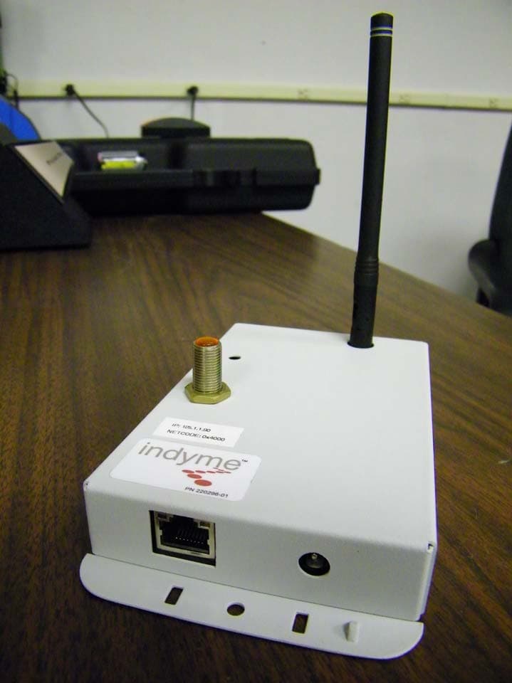
Click to zoom
Application Details
- Equipment Class
- DSS - Part 15 Spread Spectrum Transmitter
- Date of Grant
- Oct 18, 2011
- Application Purpose
- Original Equipment
- Date of Application
- Oct 17, 2011
- Equipment Note
- Wireless Access Point
- Frequency Range
- 918.00000000 - 923.00000000
- Company
- Indyme Solutions, LLC
- Country
- United States
Documents & Files
Document Text
Text extracted from the exhibit documents filed with the FCC. Open a document above to read the original.
Users Manual
Technical Document CB951 Installation Guide Page 1 P/N 430697-00 Rev C CB951 Access Point Installation Guide The CB951 is a multi-band access point designed to decode radio frequency transmissions from any of Indyme’s multi-band wireless callboxes. The signals are relayed, via the LAN, to an Indyme server for processing. Connections to the CB951 will vary depending on the deployed configuration. The CB951 can be programmed to function in the 868MHz or 900MHz frequency spectrum. Check your configuration for details. Installation The CB951 Access Point is a ceiling-mounted device. Plan the installation such that each unit has the clearest possible “line-of-sight” to the largest possible expanse of the sales floor. The CB951 Access Point must be programmed before installation. Confirm the correct antenna is installed and all operational parameters have been set prior to installing the CB951 Access Points. Each unit will require power; this can be supplied via P.O.E. or external power supply to each unit. (12VDC, 500mA, positive tip, 2.5mm – SOLD SEPARATELY). Tools Needed: • Drill and assorted Drill Bits • Assorted Screwdrivers (Phillips and Flat Blade) • Wire Cutters Equipment Needed: • CB951 Access Point • Four (4) pair CAT5 Network Cable NOTE: Grey: 868 MHz Europe Yellow: 900 MHz USA/Australia * Plan your cable runs to avoid the following potential sources of interference; DO NOT LAY CABLE ON OR NEAR Fluorescent lighting fixtures, AC power lines, fan motors or RF transmitters. * Assure a clear line of sight between the Access Point and installed Callboxes, avoiding large metallic objects such as storage racks and air ducting. * Leave at least 15 feet of excess cable at the Access Point location, in the event that the unit needs to be relocated. * Do not bundle the cable with other data cables, as “bleed-over” may occur, causing interference. Technical Document CB951 Installation Guide Page 2 P/N 430697-00 Rev C Position and Install the CB951 Access Point Depending on the location and the ceiling type, the CB951 Access Point can be mounted on a beam or through a ceiling tile: • Tile/Ceiling-mounted CB951: Install the unit above the ceiling tile with the antenna and LED barrel protruding through the ceiling tile. Verify that the LED barrel and antenna are visible from the sales floor. • Open-Beam-mounted CB951: Using zip-ties or hardware, attach the CB951 Access Point to the bottom of the beam. Verify that the LED barrel and antenna are visible from the sales floor. Try to mount the Access Point lower than nearby ducting and electrical conduits. Wiring The CB951 can be wired using an RJ-45 connector, (568B standard LAN), using CAT5 Network Cable. The CB951 must be connected using one of the following: • P.O.E. Switch: Using a CAT5 Network Cable connect one RJ45 to the LAN port on the CB951 Access Point. Connect the other end of the cable to an available port on the P.O.E. switch. • Standard Switch: Using a CAT5 Network Cable connect one RJ45 to the LAN port on the CB951 Access Point. Connect the other end of the cable to an available port on the switch. Connect the AC adapter to an available power outlet, connect the other end to the DC power jack on the Access Point. To 12VDC Adapter (positive tip) To network P.O.E. switch or Standard switch CB951 Mounting Template Depending on the location of the Access Point and the ceiling type, the following template may be used to accurately mark the holes for the antenna and the indicator L.E.D. The CB951 Access Point can be mounted on a beam or through a ceiling tile. Technical Document CB951 Installation Guide Page 3 P/N 430697-00 Rev C FCC Notice of Compliance: This device complies with Part 15 of the FCC Rules. Operation is subject to the following two conditions: (1) This device may not cause harmful interference, and (2) This device must accept any interference received, including interference that may cause undesired operation. This equipment has been tested and found to comply with the limits for Class B Digital Device, pursuant to Part 15 of the FCC Rules. These limits are designed to provide reasonable protection against harmful interference in a residential installation. This equipment generates and can radiate radio frequency energy and, if not installed and used in accordance with the instructions, may cause harmful interference to radio communications. However, there is no guarantee that interference will not occur in a particular installation. If this equipment does cause harmful interference to radio or television reception, which can be determined by turning the equipment off and on, the user is encouraged to try to correct the interference by one or more of the following measures. • Reorient or relocate the receiving antenna • Increase the separation between the equipment and receiver • Connect the equipment into an outlet on a circuit different from that to which the receiver is connected • Consult the dealer or an experienced radio/TV technician for help Any changes or modifications not expressly approved by the party responsible for compliance could void the user’s authority to operate the equipment.
ID Label/Location Info
All materials and finishes shall comply with European Union restrictions of hazardous substances. (RoHS) Alternate materials must have RoHS compliance and be approved by Indyme. White Vinyl, Black Print Material: RF T -4911 Overlaminate: 1mil Clear Polypropylene, RL-TCC-UL2000 Adhesive: TS523 3.0 2.0 radius 1/8" 4 plcs B 220198-15 CB951FCC/CE/C-tick Label 1/21/11Larry O For Art Work Reference 220198-15_B CB951 FCC.EPS 1/21/11 REVISIONS REV.DESCRIPTIONDATEAPPROVED ARelease to Manufacture1/21/11Andrea B BAdd French for IC3/18/11Andrea B 63 μIN .X .XX .XXX ±.025 ±.010 ±.005 ± 0.5 º MFG APPR ENG APPR DRAWN APPROVALSDATE CHECKED COMMENTS INTERPRET GEOMETRIC TOL PER: ASME Y14.100 - 2000 Sheet1 OF 1 FINISH MATERIAL A SCALE REV DWG NO. CAGE CODE SIZE THIS DOCUMENT IS THE PROPERTY OF INDYME AND IS CONSIDERED COMPANY CONFIDENTIAL. THE REPRODUCTION OR USE OF INFORMATION HEREIN, ALL OR IN PART, IS EXPRESSLY PROHIBITED WITHOUT WRITTEN CONFIRMATION FROM A PRINCIPAL MEMBER OF MANAGEMENT AT INDYME. 2:1 2:1 Indyme Solutions G King UNLESS OTHERWISE SPECIFIED DIMENSION TOLERANCES ARE DECIMAL: IN: ANGLES:
RF Exposure Info
Prediction of MPE limit at a given distance Equation from page 18 of OET Bulletin 65, Edition 97-01where: S = power density P = power input to the antennaG = power gain of the antenna in the direction of interest relative to isotropicR = distance to the center of radiation of the antenna Maximum peak output power at antenna input terminal: 10.38 (dBm) Maximum peak output power at antenna input terminal: 10.9 (mW) Antenna gain(typical): 1.282 (dBi) Maximum antenna gain: 1.343 (numeric) Prediction distance: 20 (cm) Sourse Based Time Average Duty Cycle: 100 (%) Prediction frequency: 923 (MHz) MPE limit for uncontrolled exposure at prediction frequency: 0.615 (mW/cm^2) Power density at prediction frequency: 0.00292 (mW/cm^2) Power density at prediction frequency: 0.0292 (W/m^2) Margin of Compliance: 23.2 (dB) EIRP 0.0147 Watts 2 4 R PG S π =
Test Report
Nemko USA, Inc. 11696 Sorrento Valley Rd., Suite F San Diego, CA 92121-1024 Phone (858) 755-5525 Fax (858) 452-1810 CERTIFICATION TEST REPORT FCC Part 15 Subpart C, 15.247 IC RSS-210 Issue 8 December 2010 IC RSS-Gen Issue 3 December 2010 For The Access Point Model: CB951 FCC ID: J69CB951 IC: 1809A-CB951 P REPARED FOR: Indyme Solutions, Inc. 8295 Aero Place San Diego, CA 92123 Prepared on: April 12, 2010 Report Number: 2010 04130097A FCC Rev. 1 Revised Sept. 13, 2011 Project Number: 29283 NEx Number: 130097 Total Pages: 34 Nemko USA, Inc 11696 Sorrento Valley Road, Suite F, San Diego, CA 92121 Phone (858) 755-5525 - Fax (858) 452-1810 DATE DOCUMENT NAME DOCUMENT # PAGE April 12, 2010 Indyme Solutions, Inc. - CB951 - RTTE Test Report FCC ID: J69CB951 IC: 1809A-CB951 2010 04130097A FCC Revision 1 2 of 34 DOCUMENT HISTORY REVISION DATE COMMENTS - April 12, 2010 Prepared By: Alan Laudani - April 12, 2010 Initial Release: Alan Laudani 1 September 13, 2011 Revision 1 to revise Number of Hopping channels Alan Laudani NOTE: Nemko USA, Inc. hereby makes the following statements so as to conform to Chapter 10 (Test Reports) Requirements of ANSI C63.4 (2003) “Methods and Measurement of Radio-Noise Emissions from Low-Voltage Electrical and Electronic Equipment in the Range of 9 kHz to 40 GHz”: o The unit described in this report was received at Nemko USA, Inc.'s facilities on September 29, 2009. o Testing was performed on the unit described in this report on September 29, 2009 to April 12, 2010 o Testing was reviewed and revised by further tests September 8, 2011 to September 13, 2011. o The Test Results reported herein apply only to the Unit actually tested, and to substantially identical Units. o This report does not imply the endorsement of the Federal Communications Commission (FCC), Industry Canada, NVLAP or any other government agency. This Report is the property of Nemko USA, Inc., and shall not be reproduced, except in full, without prior written approval of Nemko USA, Inc. However, all ownership rights are hereby returned unconditionally to Indyme Solutions, Inc., and approval is hereby granted to Indyme Solutions, Inc., and its employees and agents to reproduce all or part of this report for any legitimate business purpose without further reference to Nemko USA, Inc. Nemko USA, Inc 11696 Sorrento Valley Road, Suite F, San Diego, CA 92121 Phone (858) 755-5525 - Fax (858) 452-1810 DATE DOCUMENT NAME DOCUMENT # PAGE April 12, 2010 Indyme Solutions, Inc. - CB951 - RTTE Test Report FCC ID: J69CB951 IC: 1809A-CB951 2010 04130097A FCC Revision 1 3 of 34 TABLE OF CONTENTS DOCUMENT HISTORY ..................................................................................................................................... 2 CERTIFICATION ................................................................................................................................................ 4 1. ADMINISTRATIVE DATA AND TEST SUMMARY ............................................................................. 5 1.1. ADMINISTRATIVE DATA ............................................................................................................................ 5 1.2. TEST SUMMARY ........................................................................................................................................ 5 2. SYSTEM CONFIGURATION ................................................................................................................... 6 2.1. DESCRIPTION AND METHOD OF EXERCISING THE EUT .............................................................................. 6 2.2. SYSTEM COMPONENTS AND POWER CABLES ............................................................................................. 6 2.3. DEVICE INTERCONNECTION AND I/O CABLES ............................................................................................ 6 2.4. DESIGN MODIFICATIONS FOR COMPLIANCE .............................................................................................. 7 2.5. TECHNICAL SPECIFICATIONS OF THE EUT ................................................................................................. 7 3. DESCRIPTION OF TEST SITE AND ENVIRONMENT ......................................................................... 8 3.1. DESCRIPTION OF TEST SITE ....................................................................................................................... 8 3.2. TEST ENVIRONMENT ................................................................................................................................. 8 4. DESCRIPTION OF TESTING METHODS ............................................................................................... 9 4.1. INTRODUCTION .......................................................................................................................................... 9 4.2. CONFIGURATION AND METHODS OF MEASUREMENTS FOR CONDUCTED EMISSIONS ................................. 9 4.3. CONFIGURATION AND METHODS OF MEASUREMENTS FOR FREQUENCY IDENTIFICATION ......................... 9 4.4. CONFIGURATION AND METHODS OF MEASUREMENTS FOR RADIATED EMISSIONS .................................. 10 5. TEST RESULTS ....................................................................................................................................... 11 5.1. CONDUCTED EMISSIONS TEST DATA – RECEIVE MODE ........................................................................... 11 5.2. CONDUCTED EMISSIONS TEST DATA – TRANSMIT MODE ........................................................................ 12 5.3. DUTY CYCLE MEASUREMENT ................................................................................................................. 15 5.3 OUT OF BAND EMISSIONS TEST DATA ..................................................................................................... 16 5.4. BANDWIDTH ...........................................................................…
Text truncated - open the document above for the full version.
Contact Information
Applicant
William Kepner(COO and VP of Engineering)
Technical Contact
Indyme Solutions, Inc.Greg King
[email protected]858-268-0717
9085 Aero Drive · San Diego · United States
Non-Technical Contact
Indyme Solutions, Inc.Andrea Braxton
[email protected]858-268-0717
Test Firm
Nemko USA, Inc. - San Diego EMC DivisionJan Blomgren
[email protected]760-444-3500
Technical Specifications
| # | Rule Parts | Frequency Range | Power Output |
|---|---|---|---|
| 1 | 15C | 918 MHz - 923 MHz | 11.00 mW |
Other Applications from Indyme Solutions, LLC
J69CB526
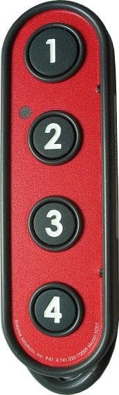
Jan 17, 2014Shopper Call Box
Equipment Class
DSC - Part 15 Security/Remote Control Transmitter
J69TYPEB
Sep 18, 2013Wireless Help Button
Equipment Class
DSS - Part 15 Spread Spectrum Transmitter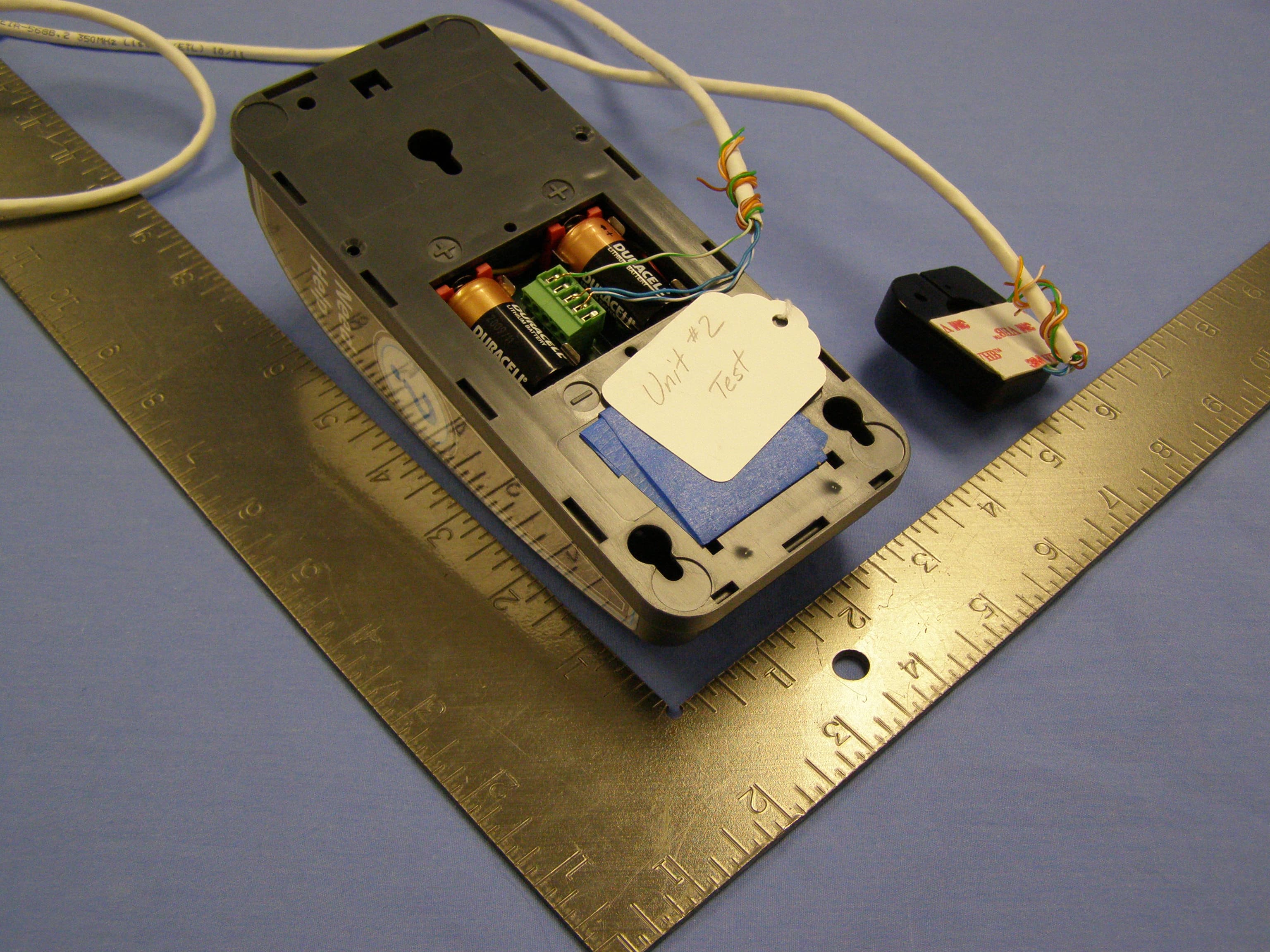
J69CB461
Mar 26, 2013Wireless Help Button
Equipment Class
DSC - Part 15 Security/Remote Control Transmitter
J69TYPEA2
Mar 12, 2013Help Button
Equipment Class
DSS - Part 15 Spread Spectrum TransmitterJ69CB529A
Apr 29, 2012Director Call Box
Equipment Class
DSC - Part 15 Security/Remote Control Transmitter