J69GENCLBXCall Box Transmitter
Indyme Solutions, LLC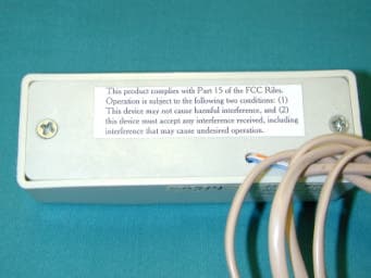
Click to zoom
Application Details
- Equipment Class
- DSC - Part 15 Security/Remote Control Transmitter
- Date of Grant
- Oct 16, 2002
- Application Purpose
- Original Equipment
- Date of Application
- Oct 16, 2002
- Equipment Note
- Call Box Transmitter
- Frequency Range
- 303.82500000 - 303.82500000
- Company
- Indyme Solutions, LLC
- Country
- United States
Documents & Files
Document Text
Text extracted from the exhibit documents filed with the FCC. Open a document above to read the original.
Users Manual
Technical Document CB440/511 Install Instructions 1 P/N: 430223-00 Rev H CB440/CB511 Installation And Programming Instruction Individual callbox addresses should be determined prior to starting the installations. As an un- programmed callbox defaults to an address of 001, this position in the control unit may be left blank or have an advisory message. Location Considerations Call boxes are generally best located at areas that require assistance to access store merchandise, such as high shelving, chain and rope cutting, key machine, etc. Stores and installers should be aware of Americans With Disabilities Act (ADA) requirements for accessibility. The call boxes utilize a very low powered transmitter, and operate best with a clear line of sight to the nearest receiver. Tall shelving, merchandise and metal signs can block or reduce the callbox signal. Install the Call Box 1. Verify call box placement with the Store Manager and determine the best mounting method. Note: Before installing the call box, verify address programming. • If mounting the call box to glass display case, affix the double-sided foam tape to the back panel of the call box. • If mounting the call box to the wall, affix the Velcro tape to the back panel of the call box. • If mounting the call box to a wood surface, open the call box and use the included hardware to secure the call box to the wooden surface. (CB440 only) 2. Install the back panel with the provided hardware. Programming CB440/CB511 Call Box Address NOTE: IF INSTALLED, JUMPER JP2 MUST BE REMOVED DURING PROGRAMMING. WHEN POWERED UP, THE CALL BOX WILL DEFAULT TO 001. The Address and Mode for each call box are listed in the Store Installation and Operation Manual for the specific store install. Refer to the data tables in Appendix A of the Store Installation and Operation Manual for the correct Mode and Address for each call box you are programming. 1. Press and hold the RESET button for approximately 5 seconds. 2. LED 1 will flash to indicate the call box is in address programming mode. 3. Press button 1 to increment the hundreds digit. LED 1 will flash with each press. 4. Press the RESET button when finished with the hundreds digit. 5. Press button 1 to increment the tens digit. LED 1 will flash with each press. CB440 (above) and CB511 (right) Technical Document CB440/511 Install Instructions 2 P/N: 430223-00 Rev H 6. Press the RESET button when finished with the tens digit. 7. Press button 1 to increment the ones digit. LED 1 will flash with each press. 8. Press the RESET button when finished with the ones digit. 9. The address just programmed should flash back on the LED 1 with a pause between each digit. (Note: the LED will indicate a zero value by staying on for a longer period of time, approximately 1 second). Revised PCA for CB440 and CB511 Mode Summary: The new CB440/511 Call Box PCA has seven operating modes as in TSN001: Wireless Call Boxes. For normal installation, each call box is programmed at the factory. If it becomes necessary to re-program the call box, please refer to the TSN001 in the Store Installation and Operation Manual for additional programming features and requirements. If the manual is not available, please contact the Indyme Help Desk at 800-829-6141 for additional support. Note: older models of these call boxes are not "Mode" programmable. Before programming these call boxes, identify what model of circuit board is installed in the unit as per the serial number or the PCA illustration above. JP1 Power: must be installed during call box programming. JP4 Pulse Width: must be installed for Narrow Pulse Width operation and programming. JP3 Mode Program Enable: must be installed during call box programming. JP2: NOT installed during call box programming. FCC Notice Of Compliance: This equipment complies with Part 15 of the FCC Rules. Operation is subject to the following two conditions: (1) This device must not cause harmful inference and (2) This device must accept any interference received, including any interference that may cause undesired operation. Any changes or modifications not expressly approved by the manufacturer could void the user's authority to operate the equipment.
Users Manual
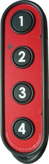
Technical Document CB514 Install Instructions 1 P/N: 430223-01 Rev B CB514 Installation And Programming Instruction Individual callbox addresses should be determined prior to starting the installations. As an un- programmed callbox defaults to an address of 001, this position in the control unit may be left blank or have an advisory message. Location Considerations Director call boxes are generally best located in high volume areas that demand a way to request additional services quickly, such as front registers or service counters. Stores and installers should be aware of Americans With Disabilities Act (ADA) requirements for accessibility. The call boxes utilize a very low powered transmitter, and operate best with a clear line of sight to the nearest receiver. Tall shelving, merchandise and metal signs can block or reduce the callbox signal. Install the CB514 Call Box 1. Verify call box and clear plastic label sleeve placement with the Store Manager. (The label sleeve is optional and may not be used in all applications.) 2. Identify which side of the CB514 the label sleeve should be attached for the best visibility and avoiding damage (the sleeve can be mounted on the left or right side of the call box). 3. Slide the label into the clear plastic sleeve (double-sided tape or Velcro will be installed on the bottom of the label sleeve). Programming the CB514 Call Box To program the CB514, program the first button and the remaining three buttons are automatically programmed with the next numerical values. When the call box "flashes" the newly programmed address, the zero value will be indicated by a longer (slightly over a second) flash. For example: an address of 001 would be shown as long flash (0), pause, long flash(0), pause, and a short flash (1). NOTE: IF INSTALLED, JUMPER JP2 MUST BE REMOVED DURING PROGRAMMING. WHEN POWERED UP, THE CALL BOX WILL DEFAULT TO 001. The Address and Mode for each call box are listed in the Store Installation and Operation Manual for the specific store install. Refer to the data tables in Appendix A of the Store Installation and Operation Manual for the correct Mode and Address for each call box you are programming. 1. Press and hold the RESET button for approximately 5 seconds. 2. LED 1 will flash to indicate the call box is in address programming mode. 3. Press button 1 to increment the hundreds digit. LED 1 will flash with each press. 4. Press the RESET button when finished with the hundreds digit. Technical Document CB514 Install Instructions 2 P/N: 430223-01 Rev B 5. Press button 1 to increment the tens digit. LED 1 will flash with each press. 6. Press the RESET button when finished with the tens digit. 7. Press button 1 to increment the ones digit. LED 1 will flash with each press. 8. Press the RESET button when finished with the ones digit. 9. The address just programmed should flash back on the LED 1 with a pause between each digit. (Note: the LED will indicate a zero value by staying on for a longer period of time, approximately 1 second). Revised PCA for CB514 Mode Summary: The new CB514 Call Box PCA has seven operating modes as defined in TSN001: Wireless Call Boxes. For normal installation, each call box is programmed at the factory. If it becomes necessary to re-program the call box, please refer to the TSN001 in the Store Installation and Operation Manual for additional programming features and requirements. If the manual is not available, please contact the Indyme Help Desk at 800-829-6141 for additional support. Note: older models of these call boxes are not "Mode" programmable. Before programming these call boxes, identify what model of circuit board is installed in the unit as per the serial number or the PCA illustration above. FCC Notice Of Compliance: This equipment complies with Part 15 of the FCC Rules. Operation is subject to the following two conditions: (1) This device must not cause harmful inference and (2) This device must accept any interference received, including any interference that may cause undesired operation. Any changes or modifications not expressly approved by the manufacturer could void the user's authority to operate the equipment. JP1 Power: must be installed during call box programming. JP4 Pulse Width: must be installed for Narrow Pulse Width operation and programming. JP3 Mode Program Enable: must be installed during call box programming. JP2: NOT installed during call box programming.
Cover Letter(s)
Good morning Tim Thank you for responding so quickly. 1) FRN Number is 0007-2511-92 2) The units with the wires/ferrite have this option. 99% of units are shipped without this option but units with the wires, have this installed at the factory and are equipped at that time with the ferrite. This is not a user installed option. 3) The unit was tested with the wire/ferrite option as this was determined to be worse case. 4) I have uploaded photos showing label location for all units. I apologize for the photo quality but are for location reference only. 5) Thanks for the info. Thanks again for the speedy response. David Light Wireless Lab Supervisor Nemko Dallas, Inc. Voice 972-436-9600 Fax 972-436-2667 email mailto:[email protected] Web www.nemkona.com > -----Original Message----- > From: Timothy R. Johnson [SMTP:[email protected]] > Sent: Wednesday, October 16, 2002 10:58 PM > To: David Light; Denise Godfrey; Tom Tidwell > Subject: Review of Indyme Electronics Inc., FCC ID: J69GENCLBX > > Tom/David, > > Attached are comments regarding review of this application. > > Thank You, > > Timothy R. Johnson, NARTE Certified EMC Engineer (No. EMC-002205-NE) > Examining Engineer > American TCB, Inc. > 6731 Whittier Ave. > McLean, VA 22101 > > email: [email protected] > alternate email: [email protected] > mobile number: 404-414-8071 > corporate phone: 703-847-4700 To: [email protected], [email protected] Subject: RE: Review of Indyme Electronics Inc., FCC ID: J69GENCLBX Page 1 of 2In 10/17/2002Printed for "Timothy R. Johnson" <[email protected]> > corporate fax: 703-847-6888 << File: ATCB Comment_ 101602.pdf >> Page 2 of 2In 10/17/2002Printed for "Timothy R. Johnson" <[email protected]>
Cover Letter(s)
American Telecommunications Certification Body Inc. 6731 Whittier Ave, McLean, VA 22101 October 16, 2002 RE: Indyme Electronics Inc. FCC ID: J69GENCLBX After a review of the submitted information, I have a few comments on the above referenced Application. 1) Please provide FRN Number of Indyme Electronics Inc. This is now required for all Grantees - (reference MD Docket No. 00-205). To obtain an FRN online, visit the FCC's Web site at www.fcc.gov and click the Commission Registration System (CORES) link. For further assistance, please either refer to the FAQ at this same link; contact the CORES helpdesk at [email protected]; or call the CORES helpdesk toll-free number: 1-877-480-3201. 2) The units appear to contain a ferrite on the "optional" cables that are shown in the external photographs. The operational description states that not all delivered units contain the wires. However it is not clear if this is something that the installer may be able to install or is only provided when ordered from the factory. There is concern regarding whether the ferrite ships with the unit and whether any necessary directions to inform the installer how to properly install the ferrite are provided (if this is a field upgradable option). 3) Please confirm if the optional cables were present in the unit tested. This can not be determined from the test photos provided. 4) The labeling provided for the 475, 511, & 514 only contain the Warning statements. The labeling provided for the 440 only shows the FCC ID Number. It is assumed that all units will contain both the FCC ID and warning statements. Please update the labeling to properly include both. 5) FYI, RF exposure exhibits are not required to be submitted for devices certified under Part 15.231. Therefore this exhibit will not be reviewed. Timothy R. Johnson Examining Engineer mailto: [email protected] The items indicated above must be submitted before processing can continue on the above referenced application. Failure to provide the requested information may result in application termination. Correspondence should be considered part of the permanent submission and may be viewed from the Internet after a Grant of Equipment Authorization is issued. Please do not respond to this correspondence using the email reply button. In order for your response to be processed expeditiously, you must submit your documents through the AmericanTCB.com website. Also, please note that partial responses increase processing time and should not be submitted. Any questions about the content of this correspondence should be directed to the sender.
External Photos
Model 440 Model 475 Model 511 Model 514
ID Label/Location Info
LABELS – ALL UNITS FCC ID LABEL AND WARNING – CB440 - BACK FCC ID LABEL CB511- END WARNING LABEL – CB 511 - BACK FCC ID LABEL – CB475 – END WARNING LABEL – CB475 – BACK FCC ID LABEL – CB514 – END WARNING LABEL – CB514 – BACK
Internal Photos
Model 440 Model 475 Model 511 Model 514
Parts List/Tune Up Info
PARTS LIST ADDENDUM Most of the electronic parts used in the construction of this call box family are on the schematic. The keypads are part of the chassis assembly so are not on the schematic. The ferrite beads that are used on the cables that attach to the relay contact sense inputs are part of the top assembly for the callbox, when it is used for contact sensing. Since each installation is unique to the particular store, these top drawings are generated when needed. The following is a list of these parts. Keypads. The following are the keypads used on each member of the GENCLBX Family of callboxes. CB511 – 150001-04 CB475 – 150001-04 CB440 – 230377-00 CB514 − 230505-00 Ferrite Beads. The following are the ferrite beads used on the contact closure sensing inputs for each member of the family. CB511 – 111017-00 CB514 – 111017-00 CB440 – 111017-01 CB475 – 111017-00
Test Report
NEMKO Test Report: 2L0355RUS1 Applicant: Indyme 9085 Aero Avenue San Diego, CA 92123 Equipment Under Test: CB511, CB514, CB440, CB475 Family (E.U.T.) In Accordance With: FCC Part 15, Subpart C For Low Power Transmitters Operating Periodically In The Band 40.66 - 40.77 MHz And Above 70 MHz Tested By: NEMKO Dallas, Inc. 802 N. Kealy Lewisville, TX 75057-3136 Authorized By: Tom Tidwell, RF Group Manager Date: 8/28/02 Total No. of Pages: 25 Nemko Dallas, Inc. FCC PART 15, SUBPART C POWER TRANSMITTERS EQUIPMENT: CB511, CB514, CB440, CB475 Family PROJECT NO.: 2L0355RUS1 Page 2 of 25 TABLE OF CONTENTS Section 1. Summary of Test Results......................................................................................3 Section 2. Equipment Under Test (E.U.T.)............................................................................5 Section 3. Equipment Configuration......................................................................................7 Section 4. Transmission Requirements...................................................................................8 Section 5. Radiated Emissions.............................................................................................11 Section 6. Occupied Bandwidth...........................................................................................18 Section 7. Block Diagrams...................................................................................................20 Section 8. Test Equipment List............................................................................................23 ANNEX A - RESTRICTED BANDS......................................................................................24 Nemko Dallas, Inc. FCC PART 15, SUBPART C POWER TRANSMITTERS EQUIPMENT: CB511, CB514, CB440, CB475 Family PROJECT NO.: 2L0355RUS1 Page 3 of 25 Section 1. Summary of Test Results Manufacturer: Indyme Model Nos.: CB511 CB514 CB440 CB475 General: All measurements are traceable to national standards. These tests were conducted on a sample of the equipment for the purpose of demonstrating compliance with Part 15, Subpart C, Paragraph 15.231. All tests were conducted using measurement procedure ANSI C63.4-1992. Radiated emissions are made on an open area test site. A description of the test facility is on file with the FCC. New Submission Production Unit Class II Permissive Change Pre-Production Unit THIS TEST REPORT RELATES ONLY TO THE ITEM(S) TESTED. THE FOLLOWING DEVIATIONS FROM, ADDITIONS TO, OR EXCLUSIONS FROM THE TEST SPECIFICATIONS HAVE BEEN MADE. None See “ Summary of Test Data”. NVLAP LAB CODE: 100426-0 Nemko Dallas Inc. authorizes the above named company to reproduce this report provided it is reproduced in its entirety and for use by the company’s employees only. Any use which a third party makes of this report, or any reliance on or decisions to be made based on it, are the responsibility of such third parties. Nemko Dallas Inc. accepts no responsibility for damages, if any, suffered by any third party as a result of decisions made or actions based on this report. This report applies only to the items tested. Nemko Dallas, Inc. FCC PART 15, SUBPART C POWER TRANSMITTERS EQUIPMENT: CB511, CB514, CB440, CB475 Family PROJECT NO.: 2L0355RUS1 Page 4 of 25 Summary Of Test Data Name of Test Paragraph No. Results Transmission Requirements 15.231(a) Complies Radiated Emissions 15.231(b) Complies Occupied Bandwidth 15.231(c) Complies Frequency Tolerance 15.231(d) N/A Alternate Field Strength Requirements 15.231(e) N/A Powerline Conducted Emissions 15.207 N/A Footnotes: The device does not operate in this band. The device does not transmit at periodic pre-determined intervals. The device is battery powered. Nemko Dallas, Inc. FCC PART 15, SUBPART C POWER TRANSMITTERS EQUIPMENT: CB511, CB514, CB440, CB475 Family PROJECT NO.: 2L0355RUS1 Page 5 of 25 Section 2. Equipment Under Test (E.U.T.) General Equipment Information Frequency Range: 303.8 MHz Nominal Operating Frequency(ies) of Sample: 303.8 MHz Type of Emission: Pulsed Supply Power Requirement: Lifetime integral battery Duty Cycle Correction Factor: -15.7 dB Description of E.U.T. The unit is a microprocessor controlled callbox that is a self contained low transmit power unit with an integral lifetime battery (estimated lifetime is 7-10 years under normal use). It is installed in a nonconductive plastic enclosure with customer specific graphic overlays. Modifications Incorporated in E.U.T. The EUT has not been modified from what is described by the brand name and unique type identification stated above. Family List Rational All the devices listed in this family utilize the same radio and printed circuit board layout. The only difference being the plastic enclosure. Nemko Dallas, Inc. FCC PART 15, SUBPART C POWER TRANSMITTERS EQUIPMENT: CB511, CB514, CB440, CB475 Family PROJECT NO.: 2L0355RUS1 Page 6 of 25 Justification The E.U.T. was configured for testing as per typical installation. The following combinations were investigated to establish worst case configuration: (1) Lying flat (2) Upright (3) Lying on edge Exercise Mode The E.U.T. exercise mode used during radiated and conducted testing was designed to exercise the various system components in a manner similar to typical use. Exercise mode: (1) Transmit all wide pulses at full power Nemko Dallas, Inc. FCC PART 15, SUBPART C POWER TRANSMITTERS EQUIPMENT: CB511, CB514, CB440, CB475 Family PROJECT NO.: 2L0355RUS1 Page 7 of 25 Section 3. Equipment Configuration Equipment Configuration List: Item Description Model No. Serial. (A) Callbox CB511 None (B) Callbox CB540 None (C) Callbox CB440 None (D) Callbox CB475 None Inter-connection Cables: Item Description Length (m) (1) The device has no detachable cables Configuration of the Equipment Under Test (E.U.T) Nemko Dallas, Inc. FCC PART 15, SUBPART C POWER TRANSMITTERS EQUIPMENT: CB511, CB514, CB440, CB475 Family PROJECT NO.: 2L0355RUS1 Page 8 of 25 Section 4. Transmission Requi…
Text truncated - open the document above for the full version.
Test Setup Photos
Nemko Dallas, Inc. FCC PART 15, SUBPART C POWER TRANSMITTERS EQUIPMENT: CB511, CB514, CB440, CB475 Family PROJECT NO.: 2L0355RUS1 Page 17 of 25 Radiated Photographs (Worst Case Configuration) FRONT VIEW REAR VIEW
Contact Information
Applicant
William Kepner(COO and VP of Engineering)
Technical Contact
Nemko Dallas Inc.Tom Tidwell
[email protected]972-436-9600
802 N Kealy · Lewisville, Texas · United States
Non-Technical Contact
Nemko Dallas Inc.Denise Godfrey
[email protected]972-436-9600
Test Firm
Nemko Dallas, Inc.Michael Cantwell
Technical Specifications
| # | Rule Parts | Frequency Range | Power Output |
|---|---|---|---|
| 1 | 15.231 | 303.825 MHz - 303.825 MHz | - |
Other Applications from Indyme Solutions, LLC
J69CB526
Jan 17, 2014Shopper Call Box
Equipment Class
DSC - Part 15 Security/Remote Control Transmitter
J69TYPEB
Sep 18, 2013Wireless Help Button
Equipment Class
DSS - Part 15 Spread Spectrum Transmitter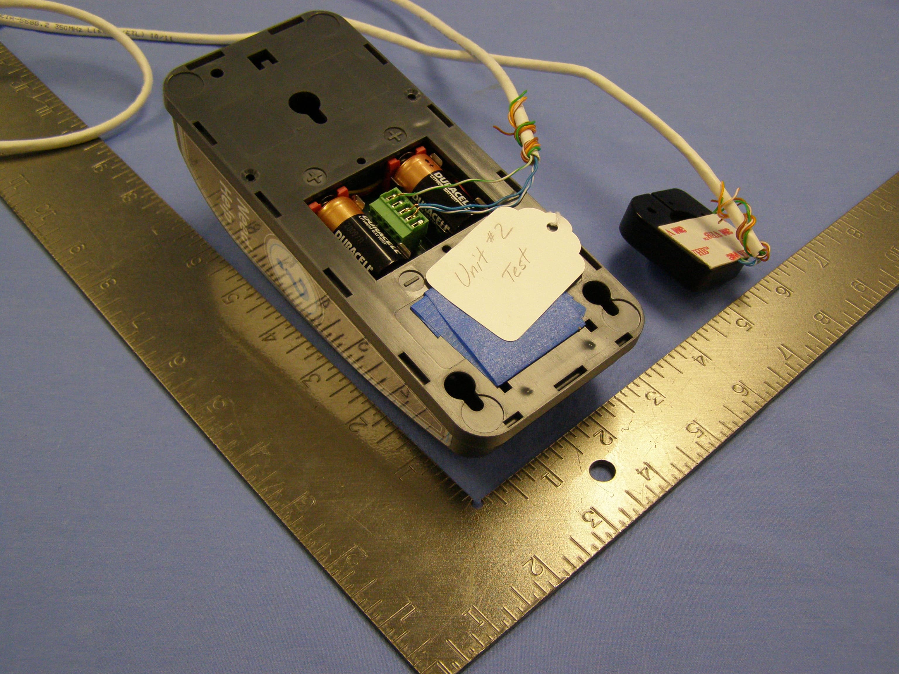
J69CB461
Mar 26, 2013Wireless Help Button
Equipment Class
DSC - Part 15 Security/Remote Control Transmitter
J69TYPEA2
Mar 12, 2013Help Button
Equipment Class
DSS - Part 15 Spread Spectrum TransmitterJ69CB529A
Apr 29, 2012Director Call Box
Equipment Class
DSC - Part 15 Security/Remote Control Transmitter