J9CGSK2HFKHands-Free Car Kit
Qualcomm Technologies, Inc.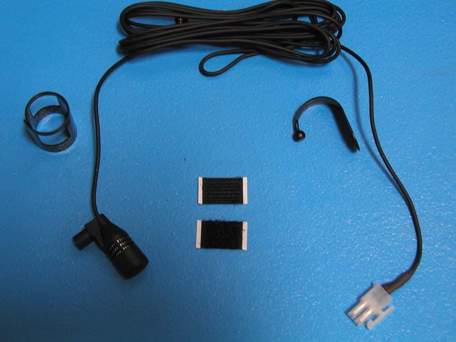
Click to zoom
Application Details
- Equipment Class
- AMP - Amplifier
- Date of Grant
- Sep 25, 2006
- Application Purpose
- Original Equipment
- Date of Application
- Sep 25, 2006
- Equipment Note
- Hands-Free Car Kit
- Frequency Range
- 1610.50000000 - 1621.35000000
- Company
- Qualcomm Technologies, Inc.
- Country
- United States
Documents & Files
Document Text
Text extracted from the exhibit documents filed with the FCC. Open a document above to read the original.
Users Manual
Plug in to speaker socket Speaker may be mounted on either side of cradle. 4Connecting the leads on the antenna cable Caution Before connecting the antenna cable to the kit, connect the leads first and follow the sequence below. Whether the vehicle ignition has an ACC position or not, connect: • Black lead ground (GND) to a clean unpainted metallic part of the vehicle. • Green lead (STEREO MUTE) to the audio system, if applicable. • Red lead to the positive terminal of the vehicle battery. • If the vehicle ignition has an ACC position, connect the yellow lead to the Ignition Sense ACC position. • If the vehicle ignition does not have an ACC position, connect the yellow lead to the ON position of the ignition (Ignition Sense). • Connect the microphone and speaker to the kit. • Connect the antenna cables to the cradle. • Connect the data cable (not included) to the kit. • Connect the optional privacy headset to the kit. • Connect the antenna cable to the kit. Caution Failure to follow these installation instructions, or bypassing the Ignition Sense, may result in the vehicle battery draining without warning. Caution Exceeding the following input voltage and current value causes the power fuse to open, requiring it to be replaced. • Maximum input voltage is 16.0 volts. • Maximum input current is 2 A. Black lead Green lead Yellow lead ACC (or ON) position STEREO MUTE Ground Red lead Battery terminal (+) Speaker Microphone Power 549AA_1999Q 2How the components fit together Note See the QUALCOMM Globalstar GIK-1700 Globalstar Installation Kit User Manual for a list of components. 1Precautions for installation 1. This kit should be professionally installed. 2. Turn off the ignition and disconnect the vehicle’s battery terminal while installing the kit. 3. Mount the Globalstar Installation Kit (GIK) so it does not interfere with normal driving operations and is not exposed to hot air from the vehicle’s heater. 4. Do not install the kit directly over any type of electrical or connecting wire or pipeline for fuel, oil, or air conditioning. 5. Do not place objects in the area over the air bag or in the air bag deployment area. Serious injury could result. 6. The kit is designed for vehicles with a negative ground 12 volt electrical system only. Other supply voltages or polarities could damage the equipment. 7. Use only the cables included in the kit to connect the exterior antenna to the kit, and only the supplied fuses for wiring. 8. After installation, check that the antenna cable and external antenna cable do not interfere with the operation of the car in any way. Make sure all of the cables operate properly. 9. After installation, make sure that all the components are secured and do not shift when the vehicle is moving or stopped. When connecting the leads on the antenna cable: 1. Make sure you do not drill through anything under the car. 2. Connect the red and then the yellow power input leads only after all other leads are connected. 3. Make firm connections. 3 Where to install the components Note The installation of the kit components may vary according to the make and model of the vehicle. The kit may also be installed in maritine vessels. Consult your local dealer for installation instructions. Caution Minimum Separation Distance Requirements The antenna must be installed so as to maintain a 25 cm (10 inch) separation distance between the antenna and the people within or near the vehicle to ensure compliance with the maximum permissible exposure (MPE) requirements. See Step 5 for antenna Minimum Separation Distance Requirements. Antenna Antenna cable Phone and cradle To p o w e r Hands-Fr e e speaker Hands-Fr e e microphone 5Mounting the antenna The antenna is required for satellite communication when the phone is used inside a vehicle. It should be mounted on the roof of the vehicle with an unobstructed view of the sky. You can attach it to the roof of the vehicle using a magnet or a ski rack type mount, or permanently bolt it in place. Note Check with your service provider for available antenna mounting options. When you mount the antenna using a magnet, check the surface of the magnet before you put the antenna on the car. The antenna is not designed for high speed driving, so use moderate speeds if it is mounted on the roof. Be sure that the connector between the antenna and the antenna cable (45-C6162-1) is inside the vehicle. Be sure to route the antenna cable through the weather strip without pinching it. Use only the antenna cables that come with the kit when connecting the antenna and do not cut or modify the antenna cable. Caution It is not recommended that you mount the antenna on the trunk or a lower surface. Performance could be affected by the shadow effect of the car. Caution Minimum Separation Distance Requirements As discussed in the GIK-1700 Globalstar Installation Kit User Manual section on Exposure to Radio Frequency Signals, when the antenna is transmitting it is necessary that at least a 25 cm (10 inch) line-of-sight separation distance be maintained between the antenna and the people within or near the vehicle, above the horizon of the antenna (above and to the side of the antenna). Maintaining this separation distance will ensure compliance with the maximum permissible exposure (MPE) requirements of the FCC rules and the international standards referenced in the section mentioned above. A 25 cm separation distance is not required below the antenna horizon, inside the vehicle. Mounting the antenna at least 25 cm from the edge of the vehicle roof will satisfy the separation distance requirement under normal use conditions. Carpet 441AA_00 GIK-1770 Antenna cable 45-C6162-1 Installation Sheet for the QUALCOMM Globalstar GIK-1700 Globalstar Installation Kit Globalstar Installation Kit Standard Components Globalstar Installation Kit Optional Accessories 80-C6304-1 Rev B M O D E S O U R C E R E L E A S E S O U N D O F F 1 23 4 5 6 R E P E A T S H U F D - B A S S D S P L S …
Text truncated - open the document above for the full version.
Users Manual
QUALCOMM Globalstar GIK-1700 Globalstar Installation Kit User Manual 80-C6303-1.book Page 1 Friday, June 30, 2006 3:12 PM Released - Internal Use Only Released - Internal Use Only Chau, Hai (hchau) 09/06/06 This manual is based on the production version of the QUALCOMM Globalstar GIK-1700 Globalstar Installation Kit. Software changes may have occurred after this printing. QUALCOMM reserves the right to make changes in technical and product specifications without prior notice. QUALCOMM Incorporated 5775 Morehouse Drive, San Diego, CA 92121-1714 Document Number 80-C6303-1 Rev B Copyright © 2006 QUALCOMM ® Incorporated All rights reserved This technology was exported from the United States Government. Diversion contrary to U.S. law prohibited. QUALCOMM ® is a registered trademark of QUALCOMM Incorporated. Digital by QUALCOMM ® is a registered trademark of QUALCOMM Incorporated. SMART KEY™ is a trademark of QUALCOMM Incorporated. Globalstar™ is a trademark of Globalstar, Inc. All other trademarks and registered trademarks are the property of their respective owners. Printed in China 80-C6303-1.book Page 2 Friday, June 30, 2006 3:12 PM Released - Internal Use Only Released - Internal Use Only Chau, Hai (hchau) 09/06/06 i Table of Contents Introduction .................................................................................1 Features .................................................................................... 1 Safety precautions when using the kit ................................... 1 Safety precautions when using the GSP-1700 Satellite Phone ......................................................................... 2 Exposure to radio frequency signals .............................................2 Antenna care ..................................................................................4 Phone operation .............................................................................4 Driving ............................................................................................4 Electronic devices ..........................................................................5 Vehicles and vessels ......................................................................6 Posted facilities ..............................................................................6 For vehicles equipped with an air bag ..........................................7 Battery care ....................................................................................7 Other safety issues ........................................................................8 Components ..................................................................................9 Globalstar Installation Kit standard components ............... 10 Component parts .................................................................... 11 Globalstar Installation Kit ..........................................................11 Speaker .........................................................................................11 Hands-free microphone ...............................................................11 Power interface cable ...................................................................11 Car Power Adapter ......................................................................13 Exterior antenna ..........................................................................13 Antenna cables .............................................................................13 Globalstar Installation Kit optional accessories .................. 14 Optional accessories (not included in kit) ............................. 15 80-C6303-1.book Page i Friday, June 30, 2006 3:12 PM Released - Internal Use Only Released - Internal Use Only Chau, Hai (hchau) 09/06/06 ii Privacy headset ............................................................................15 Privacy handset ...........................................................................15 Globalstar Data cable ..................................................................15 Operation ....................................................................................17 Using the phone in a vehicle ................................................. 17 Attaching the phone to the Globalstar Installation Kit ............17 Turning on the phone and kit .....................................................18 Charging the phone battery ........................................................19 Car stereo mute ...........................................................................20 Hands-free mode .................................................................... 20 When you use hands-free mode ..................................................21 Adjusting speaker volume ..................................................... 21 Connecting to a personal computer ....................................... 22 Privacy Headset ..................................................................... 22 Privacy headset operation ...........................................................22 Troubleshooting ........................................................................25 80-C6303-1.book Page ii Friday, June 30, 2006 3:12 PM Released - Internal Use Only Released - Internal Use Only Chau, Hai (hchau) 09/06/06 1 Introduction Before using your Globalstar Installation Kit in a vehicle, please read this manual thoroughly and retain it for future reference. Professional installation is recommended. Features The Globalstar Installation Kit (GIK) allows your Globalstar GSP-1700 satellite phone to be used as a mobile phone in your vehicle. With this kit installed in a vehicle, you can: ■Turn the phone on and off by turning the vehicle’s ignition on and off. ■Talk without picking up the phone. ■Obtain unlimited talk time using DC current supplied by your vehicle. ■Charge the phone’s battery. Safety precautions when using the kit When using your phone in a vehicle, please observe the following …
Text truncated - open the document above for the full version.
Cover Letter(s)
QUALCOMM Incorporated 5775 Morehouse Drive San Diego, CA 92121-1714 www.qualcomm.com September 7, 2006 Nemko Canada Inc 303 River Road Ottawa, Ontario, Canada K1V 1H2 Attn: Director of Certification Authority to Act as Agent On our behalf, I appoint Nemko USA, Inc. 11696 Sorrento Valley Road Suite F, Dan Diego, CA 92121, to act as our agent in the preparation of this application for equipment certification. I certify that submitted documents properly describe the device or system for which equipment certification is sought. I also certify that each unit manufactured, imported or marketed, as defined in the Federal Communications Commission’s regulations will have affixed to it a label identical to that submitted for approval with this application. For instances where our authorized agent signs the application for certification on our behalf, I acknowledge that all responsibility for complying with the terms and conditions for certification, as specified by Nemko Canada Inc, still resides with Qualcomm Incorporated, 5775 Morehouse Drive, San Diego, CA 92121. Dated this 7 Day of September 20 06 Agency agreement expiration date: September 7, 2007 By: Paul Jayne Signature Printed Title: Senior EMC Engineer On behalf of : Qualcomm Incorporated Telephone: 858-651-1758
Cover Letter(s)
QUALCOMM Incorporated 5775 Morehouse Drive San Diego, CA 92121-1714 www.qualcomm.com September 7, 2006 Equipment Autorisation Division Federal Communications Commission 7435 Oakland Mills Road Columbia, MD 21046 FCC ID: J9CGSK2HFK Product Name: Globalstar Hands-Free Kit Request for Confidentiality Pursuant to Sections 0.457 and 0.459 of the commission’s rules, we hereby request that the following documents be held confidential: • Exhibit 6 Block Diagram • Exhibit 11 Schematics • Exhibit 12 Parts List These materials contain trade secrets and proprietary information and are not customarily released to the public. The public disclosure of this information might be harmful to the company and provide unjustified benefits to our competitors. Dated this 7th Day of September 20 06 By: Paul Jayne Signature Printed Title: Senior EMC Engineer On behalf of : Qualcomm Incorporated Telephone: 858-651-1758
Cover Letter(s)
Attestation Statement GIK-1700 FCC Part 25 Application 80-C6445-1 Rev A Applicant: Qualcomm Inc. FCC ID: J9CGSK2HFK Exhibit 3 Attestation Statement The equipment, QUALCOMM model GIK-1700 Globalstar K2 Hands Free Carkit (HFK), is a satellite communications portable user terminal designed to operate under the requirements of FCC CFR47 Part 25. The product is designed to operate at a granted level of 2.51 Watts E.I.R.P. (1.53 Watts ERP). The equipment complies with uncontrolled RF exposure environment requirement by the IEEE STD C95.1 and FCC OET Bulletin 65, Edition 97-01 1997. The data, data evaluation and equipment configuration represented herein for equipment certification are a true and accurate representation of the measurements of the sample’s radio frequency interference emissions characteristics as of the dates and at the times of the test under the conditions herein specified. This applies to all tests that do not require an Open Area Test Site (OATS) to perform. Nemko USA performed tests that required an OATS site. Equipment Tested: GIK-1700 Globalstar K2 Hands Free Carkit (HFK) Part 25 References: 25.202 Frequency Stability 25.202 Emissions Limits Part Number: CV90-C6029-1 Serial Number: AA000099 Dates of Test: June 6, 2006 to August 3, 2006 Test Performed by: Paul Jayne Senior EMC/Regulatory Engineer Qualcomm Incorporated
External Photos
Exhibit 9 External Photos Applicant: Qualcomm Inc. FCC ID: J9CGSK2HFK Figure 1 HFK External -Front Figure 2 HFK External- Cables Figure 3 HFK External- Back Figure 4 HFK External-Entire Kit Figure 5 HFK External- Entire Kit Figure 6 HFK External- Microphone Detail Figure 7 HFK External- Microphone Assembly Figure 8 HFK External- ODU Antenna Figure 9 Antenna Label 1 Figure 10 Antenna Label 2 Figure 11 HFK External- Power Cable Detail Figure 12 Speaker-Rear View Figure 13 Speaker Front
ID Label/Location Info
Applicant: Qualcomm Inc. FCC ID: J9CGSK2HFK Exhibit 1 FCC Identifier Label
Internal Photos
Applicant: Qualcomm Inc. FCC ID: J9CGSK2HFK Exhibit 10 Internal Photos Figure 1 HFK Cradle Back Figure 2 HFK Cradle Front Figure 3 HFK Phone Connector Card Figure 4HFK PCB Back Detail Figure 5 HFK PCB Front- Detail Figure 6 ODU Antenna PCB Top Figure 7 ODU Antenna PCB Bottom
Operational Description
Product Overview (Part 2.1033) GIK-1700 FCC Part 25 Application 80-C6445-1 Rev A Applicant: Qualcomm Inc. FCC ID: J9CGSK2HFK Exhibit 4 Product Overview (Part 2.1033) 4.1 Technical Description The GIK-1700 “K2 Globalstar Hands Free Carkit” (HFK) operates in Globalstar mode only, communicating directly with overhead Globalstar satellites and via those satellites to the nearest Globalstar Gateway and through the Gateway to the rest of the network. The service supports voice and data communications. The Globalstar HFK uses Code Division Multiple Access (CDMA) technology to provide secure, dependable service to the user. 4.2 Address of Manufacturer and Applicant 2.1033 (c) (1) Manufacturer: Qualcomm Incorporated 5775 Morehouse Drive San Diego, CA 92121 Telephone: (858) 587-1121 Applicant: Qualcomm Incorporated 5775 Morehouse Dr. San Diego, CA 92121 Telephone: (858) 587-1121 4.3 FCC Identifier 2.1033 (c) (2) The FCC identifier is: J9CGSK2HFK 4.4 User Manual 2.1033 (c) (3) See Exhibit 8 Globalstar K2 HFK User Manual 4.5 Types of Emissions 2.1033 (c) (4) 1M25G1W Product Overview (Part 2.1033) GIK-1700 FCC Part 25 Application 80-C6445-1 Rev A 4.6 Frequency Range 2.1033 (c) (5) Each Globalstar HFK is capable of transmitting on any one of the frequency channels defined between 1610 and 1626.5 MHz. In the US and other countries where one or more TDMA mobile satellite service (MSS) low earth orbit (LEO) systems are authorized to operate, Globalstar HFKs transmit (and are authorized to transmit) in only the lower 9 of the 13 channels, operating in the frequency range from 1610 to 1621.35 MHz. Depending on local Globalstar traffic conditions, a given HFK may be assigned to operate on any of the authorized channels for a given call. Multiple access and efficient frequency re-use is provided by means of code division multiple access (CDMA) technology. 4.7 Operating Power Levels 2.1033 (c) (6) Active power control is employed in the Globalstar system to minimize collateral interference between proximate Globalstar subscribers, since as is true of any multiple access spread spectrum system, other users signals represent noise to a given users signal. Thus all signals are automatically reduced to minimum power levels by the system, transparently to the user. As defined in the Globalstar Air Interface (GAI) Specification (80-25118-1), the effective isotropic radiated power (EIRP) of a mobile HFK operating at maximum power output is 2.51 Watt. 4.8 DC Supply and Current Range 2.1033 (c) (8) The HFK is powered by an external DC power supply, which provides a nominal 12.0 V DC nominal (10.8 to 16.0 V DC range) at 300 mA to 2.0 Amperes current draw; 24 Watts maximum load. Power to the transmitter power amplifier (PA) passes through multiple switching and analog power regulator stages, and the PA never “sees” any changes in the supply voltage. It is thus virtually immune to any effects of voltage fluctuation within the defined DC power voltage input range of the HFK. Outside that range the HFK simply shuts down. 4.9 List of Semiconductor Active Devices 2.1033 (c) (10) See Exhibit 12 Parts List 4.10 Circuit Diagram 2.1033 (c) (10) See Exhibit 11 Schematics 4.11 Transmitter Tune-Up Procedure 2.1033 (c) (9) All frequency adjustments are set at the factory and there are no frequency field adjustments for this product. The transmit frequency is locked to the base station and controlled by VCTCXO adjustments to offset any possible errors. Product Overview (Part 2.1033) GIK-1700 FCC Part 25 Application 80-C6445-1 Rev A 4.12 Frequency Stability Device 2.1033 (c) (10) All RF oscillators are phase-lock loop locked to the output signal of a voltage controlled temperature compensated crystal oscillator (TCXO), the master oscillator of the system. It is specified to provide frequency accuracy to better than 5 parts per million over the HFK’s five year design life. Exhibit 14 details the temperature variation frequency stability test results which have been obtained. Due to the relatively large Doppler error inherent to an LEO communications system, transmit frequencies are locked to the TCXO signal and are not adjusted based on frequency differences with respect to Gateway transmitted signals. 4.13 Spurious Radiation Suppression Devices 2.1033 (c) (10) See Exhibit 6 and Exhibit 11 4.14 Drawing of Equipment Identification Plate or Label 2.1033 (c) (11) See Exhibit 5 Identifier Label 4.15 Photographs 2.1033 (c) (12) See Exhibit 9 and Exhibit 10 4.16 Modulation Technique 2.1033 (c) (13) The Globalstar Air Interface uses a modified form of IS-95 to support Code Division Multiple Access. CDMA was selected for Globalstar because it represents a proven technology that can provide efficient modulation scheme for satellite communications. It is relatively interference tolerant, both from a standpoint of generation of interference to other services and tolerating outside interference. As a bonus, there is a level of security inherent in the modulation scheme. It is difficult to listen into conversations or to pirate services from the system. CDMA is able to provide good voice quality while operating at relatively low RF power levels. The Globalstar CDMA is based on the existing QUALCOMM CDMA product line used for terrestrial cellular communications. 4.17 Test Data 2.1033 (3) (14) See Exhibit 14, Exhibit 15, and Exhibit 16 4.18 RF Block Diagram See Exhibit 6 Block Diagram
Parts List/Tune Up Info
4.11 Transmitter Tune-Up Procedure 2.1033 (c) (9) All frequency adjustments are set at the factory and there are no frequency field adjustments for this product. The transmit frequency is locked to the base station and controlled by VCTCXO adjustments to offset any possible errors.
RF Exposure Info
Applicant: Qualcomm Inc. FCC ID: J9CGSK2HFK Exhibit 13 RF Exposure The following table is an analysis of the maximum permissible exposure (MPE) information for the GIK-1700 antenna. The analysis was performed in reference to FCC OET Bulletin 65. The maximum EIRP power used for the MPE calculation includes calibration error and the peak gain to represent the worst case radiated transmit power. The cable losses for the calculation are also factored into the worst case radiated power by taking the maximum power measurement at the antenna output of the associated cable(s). The worst-case separation distance is calculated to be 15.76 cm. Page1 of the Installation Instructions (Exhibit 7) specifies the minimum separation distance for the antenna to insure FCC RF safety requirements are satisfied. The minimum separation is specified at 25 cm (10 inches) The separation distance specified in the warning statement of the manual is farther then the calculated distances in order to provide an increased safety margin to the user. It should be noted that these separation distance was specified in reference to the more stringent IRPA Uncontrolled environment guidelines. Globalstar Hands-Free Kit GIK-1700 Uncontrolled/General Public Maximum Permissible Exposure Distance Calculations References: International Radiation Protection Association (IRPA) Guidelines on Protection Against Non-Ionizing Radiation, 1991 47 CFR Ch.1 (10-1-97 Edition) Part 1, Section 1.1310FCC OST Bulletin No. 65, 1985 Input numerical values are in boldface. Calculated values are in plain text. Max. Antenna Power = 891 mW = 29.50 dBm bration Error Tolerance = 0.0 dB *Calibration error is factored into the RF calibration table Minmum Cable Loss 0.0 **Power is measured at cable output so cable loss is not considered Max. Antenna Gain = 4.5 dBic EIRP = 2511 mW 1523.62 mW = 34.00 dBm EIRP 31.83 dBm ERP 1991 IRPA Guidelines Uncontrolled MPE = f/2000 mW/cm^2; f = frequency in MHz1997 FCC Uncontrolled MPE = 1.0 mW/cm^2 Far-Field Power Density Calculations (in phase addition, worst case) Elemental Dipole Far-Field Distance = lambda/(2 pi) Free Space P.d = EIRP/(4 * pi * r^2) Aperture Near-Field Bound = D^2 / (4 lambda) 100% Ground Reflection P.d = EIRP/( pi * r^2) Radiating Near-Field Bound = D^2 / lambda Radio Broadcast Towers P.d = (1.6)^2 * EIRP/( 4 *pi * r^2) (60% Ground Reflection per EPA) = 0.64 EIRP/( pi * r^2) IRPA Guideline Uncontrolled MPE Safe Approach DistanceFrequency (MHz) Wavelength (cm) Elemental Dipole Far-Field Dist. (cm) IRPA MPE (mW/cm^2) Distance to Free Space MPE (cm) Distance to 100% Ground Reflection MPE (cm) 1610 18.63 2.97 0.805 15.76 31.51 1618 18.54 2.95 0.809 15.72 31.43 1621.35 18.50 2.94 0.811 15.70 31.40 1626.5 18.44 2.94 0.813 15.68 31.35 FCC Uncontrolled MPE Safe Approach DistanceFrequency (MHz) Wavelength (cm) Elemental Dipole Far-Field Dist. (cm) FCC MPE (mW/cm^2) Distance to Free Space MPE (cm) Distance to 100% Ground Reflection MPE (cm) 1610 18.63 2.97 1.000 14.14 28.27 1618 18.54 2.95 1.000 14.14 28.27 1621.35 18.50 2.94 1.000 14.14 28.27 1626.5 18.44 2.94 1.000 14.14 28.27
Test Report
Channel 7 (mid band) carrier off conducted emissions 1559-1610 MHz
Test Report
Applicant: Qualcomm Inc. FCC ID: J9CGSK2HFK Exhibit 14 Frequency Stability Exhibit 13- Transmitter Carrier Frequency Stability- FCC Part 2.1055 Transmitter RF Carrier Frequency Stability- FCC Part 2, Paragraph 2.1055 Measured with an Anritsu MT8803 Globalstar User Terminal Tester Variation from carrier frequency reference (Hz)-Channel 1 10.8V12.0V16VSpecification temp CHz offsetHz offsetHz offsetlower limitupper limit -30-952-1148-1021-40254025 -20-1012-1268-952-40254025 -10-988-1252-1145-40254025 0-856-963-752-40254025 10-658-849-863-40254025 20-412-576-552-40254025 25-55-152-485-40254025 30-74-178-312-40254025 40-145-126-104-40254025 50-257-220-48-40254025 60-615-477-436-40254025 Variation from carrier frequency reference (Hz)-Channel 9 10.8V12.0V16VSpecification temp CHz offsetHz offsetHz offsetlower limitupper limit -30-815-1122-995-40604060 -20-1055-1018-872-40604060 -10-1122-884-785-40604060 0-882-846-748-40604060 10-874-526-676-40604060 20-725-471-442-40604060 20-334-106-289-40604060 30-145-88-204-40604060 40-60-72-73-40604060 50-155-224-58-40604060 60-428-362-224-40604060 Channel 1 Frequency Stability -5000 -4000 -3000 -2000 -1000 0 1000 2000 3000 4000 5000 -30-20-10010202530405060 temp (degrees C) variation from carrier frequency reference (Hz) 10.8VDC 12.0VDC 16.0VDC Lower Limit Upper Limit Channel 9 Frequency Stability -5000 -4000 -3000 -2000 -1000 0 1000 2000 3000 4000 5000 -30-20-10010202530405060 temp (degrees C) variation from carrier reference (Hz) 10.8VDC 12.0VDC 16.0VDC Lower Limit Upper Limit
Test Report
Applicant: Qualcomm Inc. FCC ID: J9CGSK2HFK Exhibit 16 Conducted Test Data Max Power Channel 1 Max Power Channel 7 Max Power Channel 9 Out of band spurious emissions Occupied Bandwidth Channel 1 Channel 7 Channel 9 Emission Mask Channel 1 Channel 7 Channel 9 1605-1610 MHz Spurious Emissions Channel 1 Channel 7 Channel 9 Narrowband 1605-1610 MHz Channel 1 Channel 7 Channel 9
Test Report
Nemko USA, Inc. 11696 Sorrento Valley Road, Suite F San Diego, CA 92121-1024 Tel: 858 755-5525 Fax: 858 452-1810 _____________________________________________________________________________________ September 21, 2006 Paul Jayne Qualcomm Inc. 5775 Morehouse Drive San Diego, CA 92121 Re: GSP-1700HFK Globalstar K2 Hands Free Car Kit Nemko Project Number: 26-682-QUA Dear Mr. Jayne This letter is intended to serve as a notice that the GSP-1700HFK Globalstar K2 Hands Free Car Kit, as tested, has complied with the following test per client request: Test Specification Test Name FCC Part 25 Transmitter Harmonic Test Please keep us in mind for your next project and call with any questions. Sincerely, Mike T. Krumweide EMC Supervisor 1. Radiated Emissions Test Results Radiated Emissions Data CompleteXJob # :26-634-QUATest # :1 PreliminaryPage1of1 Client Name :Qualcomm Inc. EUT Name :Globalstar K2 Hands-Free Car Kit (HFK) EUT Model # :GSP-1700HFK EUT ANTENNA Part # : EUT Serial # : EUT Config. :Tested with Qualcomm GSP-1700 User Terminal Specification :FCC Part 25 Transmitter Harmonics Testing Reference : Rod. Ant. #:NATemp. (deg. C) :26Date : 7/28/2006 Bicon Ant.#:NAHumidity (%) :56Time : 8:30AM Log Ant.#:NAEUT Voltage :12VDCStaff :Mike krumweide DRG Ant. #877EUT Frequency :Photo ID: Dipole Ant.#:NAPhase:Peak Res Bandwidth:5 kHz Cable#:40ftLocation:SOATSPeak Video Bandwidth 5 kHz Preamp#:842Distance:3MAVE Res Bandwidth: Spec An.#:835AVE Video Bandwidth QP #:NA PreSelect#:NA Meas.EUTAnt.Pass Freq. CF (db)RotationHeightFail (MHz)pkavpkavpkavpkavpkavUnc.Comment 3221.4651.150.66.457.594.0-36.5180.01.2Pass16.7 dB attenuation 4832.237.644.8-4.95239.8594.0-54.2180.01.2Pass 6442.940.543.7-1.71841.9894.0-52.0180.01.7Pass 8053.723.923.99.398933.394.0-60.7180.01.3PassNoise Floor 9664.423.223.29.432.694.0-61.4180.01.3PassNoise Floor 11275.123.323.314.838.1194.0-55.9180.01.4PassNoise Floor 12886.024.624.617.642.2494.0-51.8180.01.4PassNoise Floor 14497.024.924.920.144.9994.0-49.0180.01.5PassNoise Floor 16107.024.024.023.547.4594.0-46.6180.01.5PassNoise Floor 3233.846.349.56.656.194.0-37.9180.01.2Pass16.9 dB attenuation 4850.745.045.5-4.341.2594.0-52.8180.01.2Pass 6467.639.842.71.243.8894.0-50.1180.02.0Pass 8084.425.525.55.430.8794.0-63.1180.01.3PassNoise Floor 9701.418.618.69.42894.0-66.0180.01.4PassNoise Floor 11318.420.420.414.835.2194.0-58.8180.01.4PassNoise Floor 12935.219.619.617.637.2494.0-56.8180.01.5PassNoise Floor 14552.118.719.320.739.9994.0-54.0180.01.5PassNoise Floor 16169.018.718.823.542.2594.0-51.8 3241.147.049.06.955.994.0-38.1180.01.2Pass17.2 dB attenuation 4861.741.244.8-4.340.5594.0-53.5180.01.2Pass 6482.340.241.91.243.0894.0-50.9180.01.5Pass 8102.925.325.35.430.6794.0-63.3180.01.3PassNoise Floor 9723.418.418.49.427.894.0-66.2180.01.4PassNoise Floor 11344.019.219.114.834.0194.0-60…
Text truncated - open the document above for the full version.
Contact Information
Applicant
Paul Guckian(Vice President, Regulatory Engineering)
Technical Contact
Qualcomm IncorporatedPaul Jayne
[email protected]858-651-1758
5775 Morehouse Drive · San Diego, California · United States
Non-Technical Contact
Qualcomm IncorporatedPaul Jayne
[email protected]858-651-1758
Test Firm
Nemko USA, Inc.Rhonda Saxon
Technical Specifications
| # | Rule Parts | Frequency Range | Power Output | Emission | Tolerance |
|---|---|---|---|---|---|
| 1 | 25 | 1.61 GHz - 1.62 GHz | 2.51 W | 1M25G1W | 5.0000000000 ppm |
Other Applications from Qualcomm Technologies, Inc.
J9C-M2X75
Aug 13, 2024Module
Equipment Class
CBE - Citizens Band End User DevicesJ9C-M2X72
Aug 13, 2024Module
Equipment Class
PCB - PCS Licensed Transmitter
J9C-QCNCM825
Aug 26, 2023Qualcomm WiFi 7/BT Combo module
Equipment Class
6CD - 15E 6 GHz Low Power Dual Client
J9C-QCNCM865
Apr 04, 2023Qualcomm WiFi 7/BT Combo module
Equipment Class
NII - Unlicensed National Information Infrastructure TX
J9CQCARD7280N
Nov 07, 2022QCARD7280
Equipment Class
DTS - Digital Transmission System