J9CGSPDM1Globalstar GSP-1620 Satellite Packet Data Modem
Qualcomm Technologies, Inc.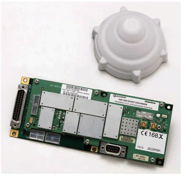
Click to zoom
Application Details
- Equipment Class
- TNB - Licensed Non-Broadcast Station Transmitter
- Date of Grant
- Sep 10, 2000
- Application Purpose
- Original Equipment
- Date of Application
- Jun 13, 2000
- Equipment Note
- Globalstar GSP-1620 Satellite Packet Data Modem
- Frequency Range
- 1610.00000000 - 1621.35000000
- Company
- Qualcomm Technologies, Inc.
- Country
- United States
Documents & Files
Document Text
Text extracted from the exhibit documents filed with the FCC. Open a document above to read the original.
Users Manual
Packet Modem Spec Rev6.doc106/09/00 Qualcomm GSP 1620 Globalstar Satellite Packet Data Modem Product Specification Packet Modem Spec Rev6.doc206/09/00 1. Globalstar Overview Globalstar is a voice and data telecommunications system utilizing a constellation of 48 Low Earth Orbiting (LEO) satellites, providing near world wide coverage (70N to 70S latitudes). GlobalstarLP (GLP), the owner / operator of the LEO constellation, is a strategic partnership comprised of many of the world’s leading telecommunications providers: • Globalstar USA, Canada, and Mexico (formerly known as Vodaphone / Airtouch) • Alenia Marconi • China Telecom • DACOM • Daimler-Chrysler Aerospace • Elsacom • Hyundia • TESAM (joint venture between France Telecom and ALCATEL) • Space Systems / Loral • Qualcomm, Inc • Vodaphone The Globalstar system is comprised of a Space Segment, and a Ground or Earth Segment. Packet Modem Spec Rev6.doc306/09/00 1.1.1 Space Segment The Space Segment is comprised of 48 LEO Satellites (and 8 additional in orbit spares) built by Loral Space Systems and operated by Globalstar LP in San Jose, CA. The advantages of a LEO satellite over MEO / GEO’s is the minimal delay, multi satellite handoff, extremely small antenna, lower power consumption, very small delay (~250 ms or comparable to terrestrial digital cellular), and the cheaper cost to the user. 1.1.2 Ground Segment The Ground Segment is comprised of Earth Stations, called Gateways that provide service in specific geographical areas. The Gateways are deployed worldwide and communicate via C Band frequencies to / from the LEO Satellites which serve as “bent pipe” transponders. The User Terminal (Phones and Modem Modules) communicate to / from the Gateway ground station using L and S band Frequencies, via the LEO satellites. Packet Modem Spec Rev6.doc406/09/00 1.1.3 Coverage 1.1.4 Carriers Each coverage territory, typically aligned with country boundaries, has one or more Service Providers, which provide the user service, similar to a “cellular” model. The Service Provider or Carrier is licensed by Globalstar to offer service in a part of the world wide coverage area (one or more countries). The Service Provider offers “airtime” to the OEM or end user, as well as providing a customer care center, and billing records for the satellite air time used and the packet data traffic sent and received. As Service Providers vary by region around the world, it is best to refer to the Globalstar Web Page to identify the correct service provider in your area of interest. http://globalstar.com. Packet Modem Spec Rev6.doc506/09/00 1.1.5 Distributors and OEMs: For the regular Globalstar Tri Mode Phone, cellular and satellite distributorships provide customers retail sales conduits to purchase, provision, and repair Tri Mode Phones throughout the world. For the GSP 1620 Packet Data Modem OEM’s and VARs directly integrate the module into a market specific product which is then resold to a business / industrial customer. The OEM/VAR may be able to buy bulk airtime from a Gateway Service Provider, and bulk modules (in units of 50) direct from Qualcomm. The OEM then integrates the Modem into their product line. Packet Modem Spec Rev6.doc606/09/00 2. Module Description <Venkat Rangan has the original drawing> Globalstar Packet Data Module Interface Port D M Por t Field Upgrad e Port DC Power 5.2V- 16V User Data Applicatio n User Module Controlle r Serial Control port Serial Data Port Outdoor Unit (Antenna) Diagnostic Monitor/ Programming Support Tool The GSP 1620 Packet Data Modem is a bare board “sandwich” stack of CCAs (Circuit Card Assemblies) comprised of a Globalstar RF board, and a Globalstar Digital board. The digital board contains all the digital electronics required by the modem and some of the power management electronics. The RF board contains the baseband converters, receiver, RF power amp, upconverters and downconverters, TCXO, synthesizers, and the remaining power electronics. The module is offered without a mechanical enclosure as it is anticipated that the OEM VAR will be integrating and packaging the module with the end users application. Packet Modem Spec Rev6.doc706/09/00 The Packet Data Modem operates in the “Globalstar (or satellite) packet data mode only”, as opposed to the Tri Mode Phone Product which has the additional Terrestrial Cellular (Analog and Digital) and Voice Capabilities. The module is powered by an external voltage source provided by the user and is intended for use in Supervisory Control and Data Acquisition (SCADA), remote telemetry / monitoring, asset tracking and monitoring and other vertical market applications. A weather proof Dielectric Resonator Antenna (DRA), sometimes referred to as an Outdoor Unit (ODU) with SMA bulkhead connectors is included. The required mating cable (SMA to MCX connectors) will be provided by the OEM / VAR in order to meet customer antenna length options. A single DB-25 (Male) connector is used for the User Interface Port. The DB-25 carries DC Power, as well as the Data and Control RS 232 signals to / from the application (DTE) to the module (DCE). A Qualcomm Diagnostic Monitor (DM) Port is provided for Software Configuration, Network Provisioning, Software Upgrades, performance data collection, and operational diagnostics. Packet Modem Spec Rev6.doc806/09/00 3. Typical Applications Satellite Internet GS Gateway Router Ethernet Server SW Globalstar Module Serial Connection SCADA Terminal Control Port Data Port DTE DCE Module ODU RxTx A typical use of the GSP 1620 is depicted above showing a SCADA application. As shown the GSP 1620 can be thought of as a 9.6Kbps Full Duplex Satellite Modem. The modem uses typical Hayes AT commands (see Chapter 4). Standard RS232 interfaces facilitate ease of use and OEM / VAR application integration. The OEM VAR provides the custom Data Terminal Equipment or DTE which manages the field processing of data, and reports process exceptions, performance reports, alarm …
Text truncated - open the document above for the full version.
Users Manual
GSP 1620 Globalstar Satellite Packet Data Modem Product Specification Errata Sheet Input Modifications to add MPE Distance Restriction Statements and Other RF Safety Statements to Section 8, Certification/Restrictions, and to be incorporated in the forthcoming User Guide for the Module: Add following new text, Section 8.3 Radio Frequency Exposure Restrictions, and Section 8.4 Electronic Device Restrictions: 8.3Radio Frequency Exposure Restrictions This section describes RF exposure safety issues related to using a GSP 1620 Modem, explains how to avoid excessive levels of RF exposure, and provides language which should be incorporated into the End User documentation (User Guide and Installation Manual), to satisfy FCC requirements. 8.3.1 Radio Frequency Energy The GSP 1620 Modem incorporates a relatively low-power radio transmitter, receiver, and antenna (the ODU). When it is ON it receives and also sends out radio frequency (RF) signals. In August 1996, the Federal Communications Commission (FCC) adopted RF exposure guidelines with safety levels for portable wireless phones and devices. Those guidelines are consistent with the safety standards previously set by both US and international standards bodies: •ANSI/IEEE C95.1-1992 Standard 1 •NCRP Report 86 (1986) 2 •ICNIRP (1996) 3 •IRPA (1991) 4 The modem is designed to comply with the established ANSI, FCC, and international safety standards for safe levels of human exposure to RF energy. Nonetheless, RF field intensity at the surface of the transmitting Globalstar antenna is fairly high. Maintaining a minimum line-of-sight separation distance of 21.5 cm (8.5 inches) between the transmitting antenna and all personnel will ensure that the General Population / Uncontrolled Exposure maximum permissible exposure (MPE) limits are not exceeded. This satisfies the MPE limits mandated by the FCC in 47 CFR Ch. 1 (10-1-99 Edition), Part 1, §1.1310 and defined in the ANSI/IEEE C95.1-1992 standard, and also satisfies the slightly more-stringent European and international exposure limit recommendations of IRPA (1991) and ICNIRP (1996). Footnotes: __________________ 1. American National Standards Institute / Institute of Electrical and Electronic Engineers 2. National council on Radiation Protection and Measurements 3. International Commission on Non-Ionizing Radiation Protection 4. International Radiation Protection Association 8.4Electronic Device Restrictions Most modern electronic equipment is shielded from RF signals. However, certain electronic equipment may not be shielded against the RF signals from wireless phones and modems. 8.4.1 Pacemakers The Health Industry Manufacturers Association recommends that a minimum separation distance of 6 inches (6”) be maintained between a handheld wireless phone and a pacemaker to avoid potential interference with the pacemaker. For a wireless modem, which has a higher power output than a wireless phone, the distance must be increased. For a GSP 1620 modem, a minimum separation distance of 10.5 inches (10”) should be maintained between the transmitting modem ODU and all pacemakers. These recommendations are consistent with the independent research by and recommendations of Wireless Technology Research, L.L.C. Persons with pacemakers: •Should always keep the modem ODU (antenna unit) more than 10.5 inches from their pacemaker when the modem is turned ON; •If you have any reason to suspect that interference is taking place, turn your modem OFF immediately. 8.4.2 Hearing Aids Some digital wireless phones and other wireless devices (including wireless modems) may interfere with some hearing aids. In the event of such interference, you may want to consult your service provider (or call the customer service line to discuss alternatives). Optional for each wireless device manufacturer. 8.4.3 Other Medical Devices If you use any other personal medical device, consult the manufacturer of your device to determine if it is adequately shielded from external RF energy. Your physician may be able to assist you in obtaining this information. Do not operate your wireless modem (turn your modem OFF) in health care facilities when any regulations posted in these areas instruct wireless phone users to do so. Hospitals or health care facilities may be using equipment that could be sensitive to external RF energy.
Attestation Statements
Applicant: QUALCOMMFCC ID: J9CGSPDM1 Exhibit 2Certification of Test Data Th e data, da ta eval uatio n, an d e qu ipm en t con fig ur ati on pr esented he re in ar e a true an d accur ate r epr esentation o f the me asure me nts o f the sa mp le’ s rad io fr eq uen cy in te rfe re nce e missi ons char acter istics as of th e dates an d at th e tim es of th e tests un de r the te st co nd iti on s spe cifie d h er ein . Th is ap pl ies to a ll te sts tha t w er e pe rform ed th at di d not r equ ir e a n Ope n Are a Test /Si te (OATS). Tests th at re qu ire d an OATS w ere p erfor med b y the TU V Pro du ct Se rvi ce s La bor atory i n San Di eg o, as i ndi ca ted i n Exh ibi t 05b . Eq ui pme nt Te sted: Glo ba lstar Sa te lli te Pa cket Da ta Mo dem M odu le , M od el GSP- 16 20 , S/N: N1 074 1GP7 Da te s o f EMC L ab Em issio ns Te sts: Ma y 26, 2 000 Te sts Pe rfo rm ed by: EM C Lab . Tech.Su za nne Ga la ti En gi nee r:Wi ll iam M oye r ________________________________________ Eq ui pme nt Te sted: : Glo bal star Sa tel li te Pa cke t Data Mod em Mo du le, M ode l GSP- 16 20 , S/N: N1 074 1H 9J Da te of C omp li ance Lab Test:Ju ne 2, 2 000 Te sts Pe rfo rm ed by: Co mp lia nce L ab . Tech.Do n Go sn ell En gi nee r:Br ia n Tho mpson ________________________________________
Cover Letter(s)
Applicant: QUALCOMMFCC ID: J9CGSPDM1 Jun e 1 2, 2 0 00 Fed er a l Co m mu ni catio n s Co m mi ssi on Office o f e ng in e er in g a nd Te ch n ol og y R e:App li catio n for Ce rti fi ca tio n o f Gl o ba lstar GSP- 16 2 0 Sa tel li te Pa cke t D ata M od em , FC C ID N o. J9 CGSPD M1 Gen tl e pe op l e: Enclo sed p l ea se fi nd th e fol lo w in g d ocum e ntati on fo r yo u r re vie w: 1 . FCC Fo rm 7 3 1, i n cl ud i ng th e fe e p ro cessi n g fo r m, fo r th e Glo b al sta r GSP- 1 62 0 Satel l ite Packe t D ata M od e m. 2 . A l etter fo r Re q ue st fo r con fi d en ti a li ty. 3 . N otifi ca ti o n of on li n e fe e p aym en t sub mi tta l b y pe r so na l cre d it ca rd ( $6 10 .0 0 ) a s pe r o nl i ne -e xecute d Fo r m 15 9 . 4 .All te st d a ta a n d su p po rt do cu m en ta tio n a s re q ui re d for ce rti fi ca tio n u nd er Par t 2 a nd Pa rt 25 o f Titl e 47 of th e Co d e of Fe de r al R e gu la tio ns Ch . 1 ( 10 - 1- 9 9 Ed i ti on ) . If an y fur the r i nfor m atio n i s r eq ui r ed p l ea se co nta ct m yse lf or Pa ul Gucki a n. You m ay co ntact m e d ir ectly b y p ho n e at 85 8- 6 58 -3 5 42 , b y fa x a t 8 58 -6 5 1- 19 8 2, o r b y e -m ai l a t wm oye r@ qu a lcom m .com . Yo u m ay co nta ct Pa ul Gucki a n di r ectl y b y p ho ne at 8 5 8- 65 1 -1 54 7 , by fa x a t 85 8 -6 51 - 19 88 , o r b y e- m ai l a t p gu cki an @q u al co m m.co m . Ple ase i nfo rm u s w he n the Re qu e st fo r Co nfi de n ti al i ty h a s be en accep te d a nd al so w he n cer ti ficati on h a s be e n gr a nted . Ver y tru ly yo ur s, Wil li a m E. Mo ye r Sr. En gi ne e r, EM C & R eg ul a to ry
Cover Letter(s)
Applicant: QUALCOMMFCC ID: J9CGSPDM1 Fed er a l Co m mu ni catio n s Co m mi ssi on Jun e 1 2, 2 0 00 R efer e nce: FCC ID : J9 CGSPD M1 R eq ue st fo r C on fid en tia li ty Pur su a nt to Sectio ns 0.45 7 a nd 0.45 9 o f the C o mm issio n’ s r ul e s, Qu al co m m Incor p or ate d he r eb y r eq ue sts co nfid e ntia l ity for ce rtai n a sp e cts o f th e i nfo rm ati on a ccom p an yi n g th i s Ap p li ca tio n for C e rtifi ca ti o n as sp eci fi ca l ly i d en ti fie d b el ow : 1. Exh ib i t 12 , GSP- 16 20 Mo de m M od u le R F Boa r d Dr a wi ng s ( Fi le s: E.12 a L D2 0- 8 21 12 _ X1 Sch e.R F.pd f, E.12 b 2 0- 82 1 12 _X2 C CA.R F.p df, a nd E.1 2c PL 20 - 82 11 2 -1 _X4 R F.pd f). 2. Exh ib i t 13 , GSP- 16 20 Mo de m OD U D ra w in gs ( Fi le s: E.13 a L D2 0- 8 20 42 _ X2 .Sche .R x.p df, E.1 3b 2 0 -8 20 4 2_ X2 C CA.R x.p df, E.1 3c PL 20 - 82 04 2 -1 _X1 R x.pd f, E.13 d L D2 0- 8 23 00 _ X1 .Sche .Tx.p df, E.1 3 e 2 0- 82 3 00 _X1 .C CA.Tx.p d f, E.13 f 1 0- 82 2 83 _X1 ODU Assy.p df, a nd E.1 3g PL2 0- 8 22 83 _ X2 OD U Asy.p d f) . 3. Exh ib i t 14 , GSP- 16 20 Mo de m M od u le D i gi ta l Boa r d Dr a wi ng s ( Fi le s: E.14 a L D2 0- 8 21 20 _ X1 .Sche m.D .p df, E.1 4b 2 0 -8 21 2 0_ X2 .CC A.D .p df, a nd E.1 4c PL 20 - 82 12 0 -1 _X4 D ig .p d f) . All i tem s con ta i n tr a de se cr ets a nd othe r p ro p ri eta ry i n fo rm a ti on no t custo m ar il y r el ea sed to the ge ne r al p u bl ic. Pu b li c d iscl o su re of th is i n fo rm a ti on wo ul d b e h ar mfu l to Qu al com m Incor p or ate d at th is ti me , a nd wo ul d p ro vid e u nj ustifie d b en efi ts to o ur co mp e ti to r s. The se ma te r ia ls co nta in p r op ri e ta ry in te l le ctu al p ro pe r ty, a nd Qu al co m m is in th e pr o ce ss of fi li ng fo r p aten t p ro tecti o n on ma ny of the se item s. Qu al co m m un d er sta nd s tha t, pu rsu an t to Ru l e 0.4 57 , d iscl o su re of a ny i n fo rm a ti on co nta in ed in th is a p pl ica ti on wi ll no t b e ma d e be for e the d a te o f g ra nt. Ver y tru ly yo ur s, Wil li a m E. Mo ye r Sr. EM C & R eg ul a to ry En gi n ee r
ID Label/Location Info
UNRELEASED INTERNAL USE ONLY DOCUMENT ID #:8a1e20 5775 MOREHOUSE DRIVE SAN DIEGO, CA 92121-1714 DCN:Rev: Title: Revision History RevDCRIncorporated ByDateChecker/EngDateCMDateRel Date ORIGINATOREMP #DATE DRAWN BYEMP #DATE ENGINEERINGEMP #DATE PROJ ENGREMP #DATE CHECKEDEMP #DATE QAEMP #DATE COMPONENT ENGEMP #DATE MANUFACTURINGEMP #DATE FINANCEEMP #DATE PROGRAM MANAGEREMP #DATE REGULATORYEMP #DATE MECHANICAL ENGEMP #DATE EMP #DATE CMEMP #DATE 15-82232X2 LABEL, REGULATORY, GS MODEM P.MARTIN 3838 04/05/00 P.MARTIN 3838 04/05/00 REQUIRED SIGNATURE ON FILE REQUIRED SIGNATURE ON FILE REQUIRED SIGNATURE ON FILE REQUIRED SIGNATURE ON FILE REQUIRED SIGNATURE ON FILE REQUIRED SIGNATURE ON FILE REQUIRED SIGNATURE ON FILE REQUIRED SIGNATURE ON FILE REQUIRED SIGNATURE ON FILE P.MARTIN 3838 04/05/00 A.MATE 6509 04/05/00 X1 34000 ----------------- -------- ----------------- -------- ----------------- -------- 04/05/00 X2 58801SIGNATUREEMP#DATESIGNATUREEMP#DATESIGNATUREEMP#DATEDATE Cage: Contract: App/Ver: 1DN14 UNRELEASED INTERNAL USE ONLY UNRELEASED INTERNAL USE ONLY
Operational Description
QUALCOMM Proprietary: Restricted Distribution (This document contains critical information about QUALCOMM products and may not be distributed to anyone that is not an employee of Qualcomm without the approval of Configuration Management) Globalstar GSP-1620 Satellite Packet Data Modem FCC Part 25 Certification Report FCC ID: J9CGSPDM1 80-98xxx-1 X1 Applicant: QUALCOMMFCC ID: J9CGSPDM1 2 QUALCOMM Incorporated 6455 Lusk Blvd. San Diego, CA, 92121-2779 U.S.A. Copyright © QUALCOMM, Incorporated, 2000. All rights reserved. Printed in the United States of America. All data and information contained in or disclosed by this document are confidential and proprietary information of QUALCOMM Incorporated and all rights therein are expressly reserved. By accepting this material the recipient agrees that this material and the information contained therein are held in confidence and in trust and will not be used, copied, reproduced in whole or in part, nor its contents revealed in any manner to others without the express written permission of QUALCOMM Incorporated. This technology is controlled by the United States Government. Diversion contrary to U.S. law prohibited. QUALCOMM Proprietary: : Restricted Distribution (This document contains critical information about QUALCOMM products and may not be distributed to anyone that is not an employee of Qualcomm without the approval of Configuration Management) Globalstar™ is a trademark of Loral Qualcomm Satellite Services, Inc. Globalstar Portable User Terminal Car Kit FCC Part 25 Certification Report FCC ID: J9CGSPDM1 80-98xxx-1 X1 June 14, 2000 Applicant: QUALCOMMFCC ID: J9CGSPDM1 3 MANUFACTURER Qualcomm Incorporated 6455 Lusk Boulevard, San Diego, CA 92121-2779 Tel: 619-587-1121 Copyright © 2000 QUALCOMM Incorporated. All rights reserved Printed in the United States of America REGULATORY ENGINEERING MANAGER Paul Guckian Director of Engineering, Regulatory Location: Qualcomm Building R, Office R-202L Tel: 858-651-1547 Fax: 858-651-1988 e-mail: [email protected] REGULATORY ENGINEERING SPECIALIST William Moyer Sr. Engineer EMC & Regulatory: Globalstar Project Location: Qualcomm Inc. Building R office R-212X. Tel: 858-658-3542 Fax: 858-651-1982 e-mail: [email protected] Applicant: QUALCOMMFCC ID: J9CGSPDM1 4 Document Amendment Record DATE DETAILS OF CHANGE (affected pages, etc.) ISSUE STATUS MANUFACTURER APPROVAL 06/14/00GSP-1620 Initial Release1William Moyer Applicant: QUALCOMMFCC ID: J9CGSPDM1 5 Cover Letter See Exhibit 1.a. Applicant: QUALCOMMFCC ID: J9CGSPDM1 6 FCC Form 731 for Globalstar GSP-1620 Satellite Packet Data Modem See Exhibit 1. b for copy of electronically-executed FCC Form 731 Applicant: QUALCOMMFCC ID: J9CGSPDM1 7 Confidentiality Request Letter See Exhibit 1.c. Applicant: QUALCOMMFCC ID: J9CGSPDM1 8 List of Exhibits ExhibitDescriptionFCC Reference 1General Information2.1033 (c) 2Certification of Test Data2.911 3aGlobalstar Compliance Lab Reverse Link Test Procedures 2.947, 2.1051 3bGlobalstar Modem Narrowband OOBE Test Plan2.947, 2.1051 4aGlobalstar Modem OOBE Test Report2.1051, 2.1049 4bConducted Modem Narrowband OOBE Test Report2.1051, 2.1049 5aGlobalstar Modem Spurious Radiated Emissions Test Plan 2.1051, 2.1049 5bGS Modem Spurious Radiated Emissions Test Report2.1051, 2.1049 6Globalstar Modem Color Photographs2.1033 (c) (12) 7Globalstar SPD Modem Maximum Permissible Exposure Analysis 1.1310, 2.1091 8Globalstar Modem Frequency Stability Data2.1055 9Globalstar Modem Identification Labels2.1033 (c) (11) 10Excepts from the Description of the Globalstar System2.1033 (c) (6), (13) 11aGlobalstar Satellite Packet Data Modem Product Spec2.1033 (c) (3) 11bGlobalstar SPD Modem Product Spec. MPE Errata Sheet 1.1310, 2.1091 12GS Modem Module RF Board Drawings2.1033 (c) (10), (12) 13GS Modem ODU Drawings2.1033 (c) (12) 14GS Modem Module Digital Board Drawings2.1033 (c) (12) Applicant: QUALCOMMFCC ID: J9CGSPDM1 9 EXHIBIT 1 GENERAL INFORMATION 1.0Introduction This document comprises the Certification Support Documentation for Certification of Qualcomm’s Globalstar (GS) GSP-1620 Satellite Packet Data (SPD) Modem. It provides the data required by the FCC for certification (formerly type acceptance) of intentional transmitters, to the requirements defined in 47 CFR Chapter 1 (10-1-98 Edition), Part 2, Sections 2.1033, 2.1046, 2.1047, 2.1049, 2.1051, 2.1053, and 2.1055 and Part 25, Sections 25.202 (f), 25.204, and 25.213 (b), and (per Report and Order FCC 98-338, adopted 12-17-98) Section 25.200 (c). The Globalstar Modem is a special purpose Globalstar User Terminal (UT), comprised of a modem module (based on the previously certified GSP- 1610 Single-Mode Phone, FCC ID: J9CGSSM1), and a separate outdoor unit (ODU) antenna (which is a modified and simplified version of the ODU used in the previously certified GCK-1410 Hands-Free Car Kit, FCC ID: J9CGSCK1A). See Section 2.0 of this exhibit and Exhibits 10 and 11. Measured data provided herein was taken using measurement procedures in accordance with Part 2 Sections 2.1041 and 2.1057. The governing regulations are those applicable in the United States of America. Much of the content of the technical description called for in the Section 2.1033 (c) rules resides in the existing, separately published, internal Qualcomm or Globalstar documents furnished in Exhibits to this application. Please note that the information provided in Exhibits 12 through 14, is considered proprietary, as discussed in the Exhibit 2 Request for Confidentiality, and is not to be freely distributed. 2.0Equipment Description The Globalstar modem module consists of stacked digital and RF circuit card assemblies (CCA’s) which provide the modem digital interface, internal power regulation, control and radio functions. The modem ODU contains the passive-transmit antenna and active-receive antenna (with remote LNA) within its protective radome housing. Like all other Globalstar user terminals (UT’s), the modem’s transmit and receive ant…
Text truncated - open the document above for the full version.
RF Exposure Info
Globalstar DRA SPDM MPE AnalysisJune 5, 2000 1 of 13 Analysis of Maximum Permissible Exposure from Globalstar Satellite Packet Data (SPD) Modem Passive-Tx Outdoor Unit (ODU) Dielectric Resonator Antennas (DRA’s) The purpose of this report is to analyze the non-ionizing electromagnetic (EM) radiation levels of the passive-Tx ODU dielectric resonator antennas employed in Satellite Packet Data Modems (SPDM’s) operating as special purpose Globalstar (GS) User Terminals (UT’s), and to compare the predicted levels with established maximum permissible exposure (MPE) levels, to determine the minimum permissible separation distance from those antennas. Within the United States, the governing regulations are those promulgated by the FCC in 47 CFR Ch. 1 (10-1-99 Edition) Part 1, Sections 1.1310 and 2.1091 [1] (unchanged from 10-1-96 Edition). Table 1 (B) in Section 1.1310 defines the MPE levels for domestic/uncontrolled exposure to RF radiation over the frequency range from 300 kHz to 100 GHz. The MPE limits are applicable to transmitting structures used at distances greater than 20 cm from the body and thus are appropriate for SPDM modules, which are used remotely or on the user’s desk top. The MPE requirements are a hybridization of those recommended by the American National Standards Institute (ANSI) in association with the Institute of Electrical and Electronic Engineers (IEEE) in ANSI/IEEE C95.1-1992 [2] and of the earlier recommendations by the National Council on Radiation Protection (NCRP) in Chapter 17 of NCRP Report No. 86, 1986 [3]. These recommended exposure limits are also similar to those defined in the IRPA Guidelines on Protection Against Non-Ionizing Radiation, 1991 [4], which are reportedly in the process of being adopted in the European Union, as codified in European Pre- Standard ENV 59166-2, approved by CENELEC in 1994. This report uses the above standards to establish the minimum safe separation distance between radiating GS SPD Modem antenna structures and people in proximity to those antennas, during GS SPD transmissions. In this report we’ve determined the power flux densities in the far field in free space, Globalstar DRA SPDM MPE AnalysisJune 5, 2000 2 of 13 above a reflecting ground plane, and below the antenna horizon, off the edge of a reflecting ground. These values may be used to determine the minimum safe distance from the antenna for US and International uncontrolled (general population) exposure environments. The analytical methodology employed is that defined in the FCC’s Office of Science and Technology Bulletin, No. 65, October 1985 [5]. For reference, Table 1 presents the maximum permissible exposure limits and averaging times for the above-described standards across the authorized transmission frequency band (1610-1621.35 MHz) for Globalstar UT antennas. As can be seen in the table, the IRPA limits represent the most severe limits in the Globalstar transmit band and subsequent discussions of limits and margins will be with respect to the IRPA limits, except where explicitly stated otherwise. Table 1. Maximum Permissible Exposure Level Requirements at Globalstar Transmit Frequencies MPE Limit Frequency (MHz) Wavelength (cm) FCC §1.1310 1997 (mW/cm 2 ) ANSI/IEEE C95.1-1992 (mW/cm 2 ) IRPA 1991 (mW/cm 2 ) Uncontrolled300-1500• f/1500•• Environment1500- 100,000 • 1.0•• 300-15000• •f/1500• 400-2000• ••f/2000 2000- 300,000 • ••1.0 161018.63 1.001.0730.805 161818.54 1.001.0780.809 1621.3518.50 1.001.0810.811 1626.518.44 1.001.0840.813 Notes: 1. f = frequency in MHz 2. Averaging time for uncontrolled exposure environments is 30 minutes for FCC and ANSI/IEEE C95.1-1992, and 6 minutes for IRPA 1991. Globalstar DRA SPDM MPE AnalysisJune 5, 2000 3 of 13 UT Transmitter and Antenna Characteristics Salient GS SPDM Transmitter and Antenna characteristics used in this analysis are presented in Tables 2, 3, and 4 and are similar to those for Globalstar Car Kit DRA Outdoor Units (ODU’s). It should be noted that although the effective isotropic radiated power (EIRP) value shown in the table is higher than that specified in the Globalstar Air Interface (GAI) Specification (Reference 6), it is none-the-less a value which could be encountered in operation, depending on the transmitter power amplifier (PA) and antenna gain calibration tolerance stackups. The value is conservative, as is appropriate for a safety analysis. Table 2. GS SPDM Transmitter and Antenna Physical Characteristics UT CharacteristicValue Transmitter Power (P t )26.5 dBm (631 mW) UT Maximum Antenna Gain (G t ) 7.0 dBic Calibration Error Tolerance (Tol) 1.0 dB EIRP (P t + G t + Tol)34.5 dBm Antenna Diameter (D) 2.5 cm (Characteristic Dimension) Antenna Depth (d) 1.0 cm Antenna Height Above Base 5.0 cm Antenna Gain Since these are omnidirectional DRA antennas designed to communicate with overhead satellites, their maximum gain is in directions well above the antenna horizon – at zenith for the GS SPDM antenna. Typical DRA antenna gain values as a function of elevation angle are presented in Table 3. There is a peak gain variation of less than 0.5 dB across the UT transmit band, with the highest in- band gain at the upper band edge, 1626.5 MHz, and those are the gain values presented in Table 3 and used in the analysis. The antenna gain is strongly direction dependant and the gain toward the ground plane beneath the antenna is substantially less than the gain in all directions above the horizon. Globalstar DRA SPDM MPE AnalysisJune 5, 2000 4 of 13 Table 3. GS SPDM Antenna Gain as a Function of ElevationAngle_ _ _ _ Elevation AngleGainGain Delta (deg.)(dBic)(dB) 906.9-0.1 857.00.0 806.8-0.2 756.7-0.3 706.5-0.5 656.3-0.7 605.9-1.1 555.5-1.5 505.0-2.0 454.7-2.3 404.1-2.9 353.6-3.4 302.9-4.1 252.4-4.6 201.5-5.5 151.1-5.9 100.2-6.8 5-0.2-7.2 0-1.2-8.2 -5-2.0-9.0 -10-3.1-10.1 -15-4.0-11.0 -20-5.3-12.3 -25-6.4-13.4 -30-7.9-14.9 -35-8.3-15.3 -40-10.0-17.0 -45-9.9-16.9 -50-10.7-17.7 -55-11.7-18.7 -60-12.7-19.7 -65-12.6-19.6 …
Text truncated - open the document above for the full version.
RF Exposure Info
QUALCOMM Proprietary: Restricted Distribution. (This document contains critical information about QUALCOMM products and may not be distributed to anyone that is not an employee of QUALCOMM without the approval of Configuration Management.) Globalstar GSP-1620 Satellite Packet Data Modem Article 3.1a Health and Safety Analysis Report 80-99280-1 X1 QUALCOMM Incorporated 5775 Morehouse Dr. San Diego, CA, 92121-1714 U.S.A. Copyright © QUALCOMM, Incorporated, 2000. All rights reserved. Printed in the United States of America. All data and information contained in or disclosed by this document are confidential and proprietary information of QUALCOMM Incorporated and all rights therein are expressly reserved. By accepting this material the recipient agrees that this material and the information contained therein are held in confidence and in trust and will not be used, copied, reproduced in whole or in part, nor its contents revealed in any manner to others without the express written permission of QUALCOMM Incorporated. This technology may be controlled by the United States Government. Diversion contrary to U.S. law prohibited. Restricted Distribution (This document contains critical information about QUALCOMM products and may not be distributed to anyone that is not an employee of QUALCOMM without the approval of Configuration Management.) Globalstar ™ is a trademark of Loral Qualcomm Satellite Services, Inc. Globalstar GSP-1620 Satellite Packet Data Modem, Article 3.1a Health and Safety Analysis Rep…
Text truncated - open the document above for the full version.
Contact Information
Applicant
Paul Guckian(Vice President, Regulatory Engineering)
Technical Contact
Qualcomm IncorporatedSuzanne Galati
[email protected]858-845-3699
5775 Morehouse Drive · San Diego, California · United States
Non-Technical Contact
Qualcomm IncorporatedSuzanne Galati
[email protected]858-845-3699
Technical Specifications
| # | Rule Parts | Frequency Range | Power Output | Emission | Tolerance |
|---|---|---|---|---|---|
| 1 | 25 | 1.61 GHz - 1.62 GHz | 2.82 W | 1M25G1W | 10.0000000000 ppm |
Other Applications from Qualcomm Technologies, Inc.
J9C-M2X75
Aug 13, 2024Module
Equipment Class
CBE - Citizens Band End User DevicesJ9C-M2X72
Aug 13, 2024Module
Equipment Class
PCB - PCS Licensed Transmitter
J9C-QCNCM825
Aug 26, 2023Qualcomm WiFi 7/BT Combo module
Equipment Class
6CD - 15E 6 GHz Low Power Dual Client
J9C-QCNCM865
Apr 04, 2023Qualcomm WiFi 7/BT Combo module
Equipment Class
NII - Unlicensed National Information Infrastructure TX
J9CQCARD7280N
Nov 07, 2022QCARD7280
Equipment Class
DTS - Digital Transmission System