J9CGSSM1Globalstar Single-Mode Portable User Terminal
Qualcomm Technologies, Inc.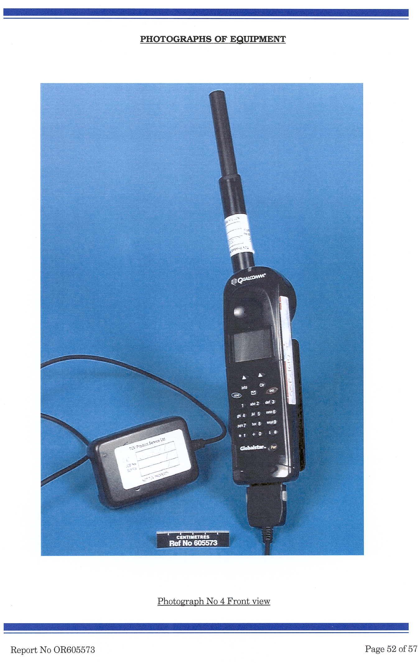
Click to zoom
Application Details
- Equipment Class
- TNE - Licensed Non-Broadcast Transmitter Held to Ear
- Date of Grant
- May 01, 2000
- Application Purpose
- Original Equipment
- Date of Application
- Dec 14, 1999
- Equipment Note
- Globalstar Single-Mode Portable User Terminal
- Frequency Range
- 1610.00000000 - 1621.35000000
- Company
- Qualcomm Technologies, Inc.
- Country
- United States
Documents & Files
Document Text
Text extracted from the exhibit documents filed with the FCC. Open a document above to read the original.
Users Manual
Applicant: QualcommFCC ID: J9CGSSM1 Single-Mode Portable UT User Guide (80-98154-1 X2) Errata Sheet Input Modifications to Correct Maximum Radiated Power Value, in Safety Issues Section: Radio frequency energy: Change title of subsection to read: “Radiofrequency energy.” Change last sentence of first paragraph to read: “The power level can range from 0.01 watt to a maximum of 1.0 watt, with 0.4 watt being the typical full power level. “
Attestation Statements
Applicant: QUALCOMMFCC ID: J9CGSSM1 Exhibit 2Certification of Test Data Th e data, da ta eval uatio n, an d e qu ipm en t con fig ur ati on pr esented he re in ar e a true an d accur ate r epr esentation o f the me asure me nts o f the sa mp le’ s rad io fr eq uen cy in te rfe re nce e missi ons char acter istics as of th e dates an d at th e tim es of th e tests un de r the te st co nd iti on s spe cifie d h er ein . Th is ap pl ies to a ll te sts tha t w er e pe rform ed th at di d not r equ ir e a n Ope n Are a Test /Si te (OATS). Tests th at re qu ire d an OATS w ere p erfor med b y the TU V Pro du ct Se rvi ce s La bor atory i n San Di eg o, as i ndi ca ted i n Exh ibi t 5b. Eq ui pme nt Te sted: SMP U T, Mo del GSP- 16 10, S/N: N 106 50 WH7 Da te of Test:Au gu st 23 , 1 99 9 Te st Per for me d b y: EM C Lab . Tech.Su za nne Gala ti En gi nee r:Wi ll iam M oye r __ __ ___ __ ___ __ ___ _
Cover Letter(s)
Applicant: QUALCOMMFCC ID: J9CGSSM1 D ecem b er 1 4 , 19 9 9 Fed er a l Co m mu ni catio n s Co m mi ssi on Office o f e ng in e er in g a nd Te ch n ol og y R e:App li catio n for Ce rti fi ca tio n o f Gl o ba lstar Si ng le - Mo de Po rta bl e U se r Ter mi n al FCC ID N o. J9 CGSSM 1 Gen tl e pe op l e: Enclo sed p l ea se fi nd th e fol lo w in g d ocum e ntati on fo r yo u r re vie w: 1 . FCC Fo rm 7 3 1, i n cl ud i ng th e fe e p ro cessi n g fo r m, fo r th e Glo b al sta r Si n gl e- M od e Por ta b le U ser Te rm in a l. 2 . A l etter fo r Re q ue st fo r con fi d en ti a li ty. 3 . N otifi ca ti o n of se pa r ate fee p a ym en t sub m itta l i n the fo rm o f a ch eck ( $6 10 .00 ) # 19 xxxx an d a cco mp an yin g e xe cu ted Fo rm 1 5 9. 4 .All te st d a ta a n d su p po rt do cu m en ta tio n a s re q ui re d for ce rti fi ca tio n u nd er Par t 2 a nd Pa rt 25 o f Titl e 47 of th e Co d e of Fe de r al R e gu la tio ns Ch . 1 ( 10 - 1- 9 8 Ed i ti on ) . If an y fur the r i nfor m atio n i s r eq ui r ed p l ea se co nta ct m yse lf or Pa ul Gu ckia n . Yo u m ay co ntact m e d ir ectly b y p ho n e at 85 8- 6 58 -3 5 42 , b y fa x a t 8 58 -6 5 1- 19 8 2, o r b y e -m ai l a t wm oye r@ qu a lcom m .com . Yo u m ay co nta ct Pa ul Gu ckia n d ir e ctly by p ho ne at 8 5 8- 65 1 -1 54 7 , by fa x a t 85 8 -6 51 - 19 88 , o r b y e- m ai l a t p gu cki an @q u al co m m.co m . Ple ase i nfo rm u s w he n the Re qu e st fo r Co nfi de n ti al i ty h a s be en accep te d a nd al so w he n cer ti ficati on h a s be e n gr a nted . Ver y tru ly yo ur s, Wil li a m E. Mo ye r Sr. En gi ne e r, EM C & R eg ul a to ry
Cover Letter(s)
Applicant: QUALCOMMFCC ID: J9CGSSM1 Fed er a l Co m mu ni catio n s Co m mi ssi on D ecem b er 1 4 , 19 9 9 R efer e nce: FCC ID : J9 CGSSM 1 R eq ue st fo r C on fid en tia li ty Pur su a nt to Sectio ns 0.45 7 a nd 0.45 9 o f the C o mm issio n’ s r ul e s, Qu al co m m Incor p or ate d he r eb y r eq ue sts co nfid e ntia l ity for ce rtai n a sp e cts o f th e i nfo rm ati on a ccom p an yi n g th i s Ap p li ca tio n for C e rtifi ca ti o n as sp eci fi ca l ly i d en ti fie d b el ow : 1. Exh ib i t 12 , Asse mb ly Dr aw i ng (Fil e : E.1 2 10 - 70 96 0 _X1.p df) 2. Exh ib i t 13 , D ig i ta l C CA D r aw in g s ( Fi le s: E.1 3a 2 0 -8 14 0 3_ X3 .PD F, E.13 b L D2 0 -8 14 0 3_ X1 .PD F, an d E.1 5c PL 20 - 81 40 3 -3 X1 .PD F) 3. Exh ib i t 14 , R F C CA D r aw in g s ( Fil es: E.1 4 a 20 - 81 37 5 _X2.PDF, E.1 4b LD 20 - 81 37 5 _X1.PDF, a nd E.14 c PL2 0- 8 13 75 - 2X2.PDF) 4. Exh ib i t 15 , Ante nn a D ra wi n gs ( Fi le s: E.1 5a C V90 -7 0 76 6_ X7.PD F a nd E.1 5b 80 -7 0 81 3- 1 _X4.PDF) All i tem s con ta i n tr a de se cr ets a nd othe r p ro p ri eta ry i n fo rm a ti on no t custo m ar il y r el ea sed to the ge ne r al p u bl ic. Pu b li c d iscl o su re of th is i n fo rm a ti on wo ul d b e h ar mfu l to Qu al com m Incor p or ate d at th is ti me , a nd wo ul d p ro vid e u nj ustifie d b en efi ts to o ur co mp e ti to r s. The se ma te r ia ls co nta in p r op ri e ta ry in te l le ctu al p ro pe r ty, a nd Qu al co m m is in th e pr o ce ss of fi li ng fo r p aten t p ro tecti o n on ma ny of the se item s. Qu al co m m un d er sta nd s tha t, pu rsu an t to Ru l e 0.4 57 , d iscl o su re of a ny i n fo rm a ti on co nta in ed in th is a p pl ica ti on wi ll no t b e ma d e be for e the d a te o f g ra nt. Ver y tru ly yo ur s, Wil li a m E. Mo ye r Sr. EM C & R eg ul a to ry En gi n ee r
ID Label/Location Info
SMP FCC Label 01 pict FCC Label 02 pict
ID Label/Location Info
SMP FCC Label 01a FCC Label 02 pict
Operational Description
Wednesday, December 15, 1999731_Form.htsPage: 1 https://svartifoss.fcc.gov/cgi-bin/ws.exe/prod/oet/forms/731/731_Form.hts?mode=print&application_id=96254 FEDERAL COMMUNICATIONS COMMISSION - FCC FORM 731 APPLICATION FOR EQUIPMENT AUTHORIZATION Approved by OMB 3060 - 0057 Expires 9/30/00 You will be presented with the FCC FORM 159, Fee Remittance Advice after submitting your application and obtaining a confirmation number. This Fee Remittance Advice, FCC Form 159, must currently be submitted in paper form along with payment to the address indicated in the FCC Fee Filing Guide. Electronic submission of FCC Form 159 is not currently available. Item 1. Applicant's complete, legal business name: Qualcomm Incorporated Item 2. Applicant's mailing address Line 1: 5775 Morehouse Drive Line 2: P.O.Box: City: San Diego State: CA Country(if foreign address): Zip/Postal Code: 92121 Item 3. FCC ID: Grantee code: J9C * Equipment Product Code (14 characters maximum): Item 4. Person at the applicant's address to receive grant or for contact: First Name: Karen Mail Stop: Last Name: Stambaugh Telephone: 858-651-2160 Ext: Title: Assoc. Quality Engineer Fax No: E-mail: [email protected] Item 5. Instead of Applicant, FCC is authorized to mail original Grant to: Firm Name: Address Line 1: P.O.Box: Address Line 2: City: State: Country(if foreign address): Zip/Postal Code: Person at above address to receive Grant: First Name: Last Name: Title: Mail Stop: Item 6. Technical Contact: Firm Name: Telephone: Ext: Fax No: First Name: Middle Initial: Last Name: Address Line 1: P.O.Box: Address Line 2: City: State: Country(if foreign address): Zip/Postal Code: E-mail: GSSM1 Qualcomm Incorporated858-658-3542858-651-1982 WilliamEMoyer 5775 Morehouse Drive San Diego CA 92121 [email protected] GSSM1 Qualcomm Incorporated858-658-3542858-651-1982 WilliamEMoyer 5775 Morehouse Drive San Diego CA 92121 [email protected] Wednesday, December 15, 1999731_Form.htsPage: 2 https://svartifoss.fcc.gov/cgi-bin/ws.exe/prod/oet/forms/731/731_Form.hts?mode=print&application_id=96254 Item 7. Non-Technical Contact: Firm Name: Telephone: Ext: Fax No: First Name: Middle Initial: Last Name: Address Line 1: P.O.Box: Address Line 2: City: State: Country(if foreign address): Zip/Postal Code: E-mail: Item 8. * Does this application include a request for confidentiality for any portion(s) of the data contained in this application pursuant to 47 CFR § 0.459 of the Commission Rules? If "Yes" see instructions. Yes No Item 9. * Does the applicant request that the Commission defer grant of this application pursuant 47 CFR § 0.457(d)(1)(ii)? (See instructions) If so, specify date when grant may be issued (MM/DD/YYYY format): Yes No Item 10. Equipment Code: * Description of Product as it is Marketed: * Equipment will be operated under FCC Rule Part(s): Item 11. * Application is for: Original Equipment (See instructions) Change in identification of presently authorized equipment: Original FCC ID: Grant Date (MM/DD/YYYY format): Class II permissive change or modification of presently authorized equipment (See instructions) Item 12 . EQUIPMENT SPECIFICATIONS: (See instructions) Frequency range in MHzRated RF power output in watts Frequency toleranceEmission designator (See 47 CFR § 2.201 and § 2.202) Microprocessor Model Number Qualcomm Incorporated858-651-1547858-651-1989 PaulGuckian 5775 Morehouse Drive San Diego CA 92121 [email protected] TNE -Licensed Non-Broadcast Transmitter Held to Ear Globalstar Single-Mode Portable User Terminal 16101621.35110 ppm 1M25G1W Qualcomm Incorporated858-651-1547858-651-1989 PaulGuckian 5775 Morehouse Drive San Diego CA 92121 [email protected] TNE -Licensed Non-Broadcast Transmitter Held to Ear Globalstar Single-Mode Portable User Terminal 16101621.35110 ppm 1M25G1W Wednesday, December 15, 1999731_Form.htsPage: 3 https://svartifoss.fcc.gov/cgi-bin/ws.exe/prod/oet/forms/731/731_Form.hts?mode=print&application_id=96254 Item 13. Is the equipment in this application: * (a) a composite device subject to an additional equipment authorization? * (b) part of a system that operates with, or is marketed with, another device that requires an equipment authorization? If either of the above questions is answered "Yes" complete section 13(c). Yes No Yes No (c) The related application: has been filed at same time as this application under the FCC ID listed to the right has been granted under the FCC ID listed to the right is in the process of being filed under the FCC ID listed to the right is pending with the FCC under the FCC ID listed to the right FCC ID Item 14. Name of test firm and contact person on file with the FCC, if different from applicant or contact person: Firm Name: First Name: Last Name: Telephone: Ext: Fax No: E-mail: Read each certification carefully before answering and signing this application WILLFUL FALSE STATEMENTS MADE ON THIS FORM ARE PUNISHABLE BY FINE AND IMPRISONMENT (U.S. CODE, TITLE 18, SECTION 1001), AND/OR REVOCATION OF ANY STATION LICENSE OR CONSTITUTION PERMIT (U.S. CODE, TITLE 47, SECTION 312(a)(1)), AND/OR FORFEITURE (U.S. CODE, TITLE 47, SECTION 503). Item 15. SECTION 5301 (ANTI-DRUG ABUSE) CERTIFICATION: The applicant must certify that neither the applicant nor any party to the application is subject to a denial of Federal benefits, that include FCC benefits, pursuant to Section 5301 of the Anti-Drug Abuse Act of 1988, 21 U.S.C. § 862 because of a conviction for possession or distribution of a controlled substance. See 47 CFR 1.2002(b) for the definition of a "party" for these purposes. Does the applicant or authorized agent so certify? Yes No Item 16. APPLICANT/AGENT CERTIFICATION: I certify that I am authorized to sign this application. All of the statements herein and the exhibits attached hereto, are true and correct to the best of my knowledge and belief. IN accepting a Grant of Equipment Authorization issued by the FCC as a result of the representations made in this application, the …
Text truncated - open the document above for the full version.
RF Exposure Info
[email protected], 4/25/00 5:03 PM -0700, Requested Information: FCC ID: J9 To: [email protected] From: Bill Moyer x8-3542 <[email protected]> Subject: Requested Information: FCC ID: J9CGSSM1 Cc: pguckian, sgalati, mcarosel, pcoan, bwallace Bcc: X-Attachments: Frank Coperich: This e-mail will be printed to disk using PDFWriter and submitted as an attachment pdf file via the filing submissions webpage. It is also being sent to you directly in parallel so that we will have a record of what was submitted, that being something the Webpage does not always provide due to time-out problems. My responses to your specific questions and comments are interleaved below in blue italics so that they may be more readily discerned. Date: Fri, 10 Mar 2000 13:11:27 -0500 From: [email protected] (OET) To: wmoyer Subject: To:William Moyer, Qualcomm Incorporated From:Frank Coperich [email protected] FCC Application Processing Branch Re:FCC ID J9CGSSM1 Applicant:Qualcomm Incorporated Correspondence Reference Number:12665 731 Confirmation Number:EA96254 Date of Original E-Mail:03/10/2000 1. The SAR values reported in the Table on page 28 of the SAR report do not match the values on all the SAR plots submitted, please clarify. The SAR Report change page, newly submitted as Exhibit E.7 change page, is consistent with the SAR values reported in Exhibits E.7 color SAR plot 01 through 013, which present the color SMP UT SAR data plots. It replaces page 28 of the SMP UT SAR Report, Exhibit E.7 SMP SAR TR. The table summarizes all SMP UT SAR test results, except those for the System Validation measurement with the calibrated dipole antenna. Only SAR magnitudes are given in the table; measurement tolerances are provided in each data plot. 2. Several plots indicated more than 6 dB power drift during the SAR measurement, while others have minimal drift. Please clarify such effects on SAR and also take into consideration following issues on peak SAR locations. Is this type of drift typical for this device or is it due to a prototype ? The reported power drift values are a test artifact. The artifact appears to be due to the combination of two factors, the extremely small SAR values measured in Globalstar mode, relative to the reported nominal dynamic range of the DASY3 system (5 uW/g to 100 uW/g), and the probe position where the power drift measurements are made. The SMP UT Globalstar mode SAR values ranged from 2.5 to 24.6 uW/g averaged over 1.0 gram tissue and 0.6 to 13.2 uW/g averaged over 10 grams tissue, values at and below the nominal dynamic range of the system. Power drift measurements are (typically and in accordance with the DASY3 manual) made at a point 1.0 cm further removed from the phone in the z axis direction of the phantom (closer to the phantom fluid surface). All other things being equal, the measured SAR at the power drift measurement point will in general be substantially smaller than the maximum SAR 1Printed for Bill Moyer x8-3542 <[email protected]> [email protected], 4/25/00 5:03 PM -0700, Requested Information: FCC ID: J9 values within the scan volume. That places the power drift measurement SMP UT SAR values outside the nominal working range of the DASY3 system. This is corroberated by the fact that the reported Globalstar mode power drift values are almost random in nature, with the following values reported by the DASY3: 6.12 dB, -5.77 dB, 5.08 dB, Reference value below zero, 1.28 dB, 0.05 dB, -1.32 dB, -9.56 dB, Reference value below zero, Reference value below zero, Reference value below zero, and -0.02 dB. The messages stating the Reference value is below zero imply some form of digital underflow problem in the software, consistent with the hypothesis that extremely small SAR values were being used in the power drift calculations. Even if the reported power drift values were real, due to reduced power output from the UT over the course of the measurement scan, applying that power drift value as a correction factor to the SAR data would only result in a slight absolute increase in the reported Globalstar SAR values. Numerically, the effect would be an increase in the maximum measured SAR value from 24.6 uW/g to 167 uW/g averaged over 1.0 gram tissue, only a bit greater than 1/10 the SAR limit value. (The reported power drift value of -9.56 dB is associated with the measured peak SAR values of 18.5 uW/g averaged over 1.0 g tissue and 10.3 uW/g averaged over 10 grams tissue, yielding the new maximum SAR value of 167 uW/g. The reported maximum value of 24.6 uW/g is associated with a reported power drift of only -1.32dB, which would yield a corrected maximum SAR value of 33.34 uW/g averaged over 1.0 gram tissue.) Thus at worst, correcting for the reported power drift (however inappropriately) would only reduce the SMP UT's substantial SAR margin with respect to the limit. Given the probable test artifact origin of the reported power drift values, the clear indication of software problems in computing some of those values, and the lack of significance to the end results relative to the SAR limit, no further testing of the SMP UT SAR characteristics and test power drift is deemed necessary. 3. The SAR plots indicated peak SAR locations are mostly at the top of the head, which were not fully included in the plots. Due to device and antenna design, the submitted plots can only confirm SAR compliance for the handset body portions. Please provide additional information and measurement results, if needed, to indicate the SAR due to portions of the antenna extending above the head does not exceed SAR limit. If necessary, measurements at the top of the head may be needed. Note: DASY3 has new software that would allow probe to be tilted up to 30 degrees for making measurements. Peak Globalstar mode SAR is across the upper forehead side (the Globalstar phone antenna detent positions result in a forward-tilting Globalstar antenna when positioning the phone on the phantom per the procedure outlined…
Text truncated - open the document above for the full version.
Test Report
Qualcomm Proprietary: Restricted Distribution. (This document contains critical information about QUALCOMM products and may not be distributed to anyone that is not an employee of QUALCOMM without the approval of Configuration Management.) Globalstar Compliance Lab Reverse Link Test Procedures 80-98735-1 X1 QUALCOMM Incorporated 6455 Lusk Blvd. San Diego, CA, 92121-2779 U.S.A. Copyright © 1999 QUALCOMM Incorporated. All rights reserved. Printed in the United States of America. All data and information contained in or disclosed by this document are confidential and proprietary information of QUALCOMM Incorporated and all rights therein are expressly reserved. By accepting this material the recipient agrees that this material and the information contained therein are held in confidence and in trust and will not be used, copied, reproduced in whole or in part, nor its contents revealed in any manner to others without the express written permission of QUALCOMM Incorporated. This technology is controlled by the United States Government. Diversion contrary to U.S. law prohibited. Qualcomm Proprietary: Restricted Distribution. (This document contains critical information about QUALCOMM products and may not be distributed to anyone that is not an employee of QUALCOMM without the approval of Configuration Management.) Globalstar TM is a trademark of Loral Qualcomm Satellite Services, Inc. Globalstar Compliance Lab Reverse Link Test Procedures 80-98735-1 X1 June 28, 1999 Globalstar Compliance Lab Reverse Link Test ProceduresTables 80-98735-1 X1QUALCOMM Proprietaryiii Table of Contents 1. Introduction .......................................................................................................1-1 1.1 Scope of this Document.................................................................................1-1 1.2 List of Abbreviations/Acronyms ...................................................................1-1 2. Applicable Documents......................................................................................2-1 2.1 Document Requirements ..............................................................................2-1 3. Requirements ....................................................................................................3-1 3.1 General ..........................................................................................................3-1 4. Procedures ........................................................................................................4-1 4.1 General ..........................................................................................................4-1 4.1.1 Measurement Notes ................................................................................4-1 4.1.2 Calibration ...............................................................................................4-1 4.1.3 Test Sequences ........................................................................................4-1 4.2 Access Probe Power Time Response.............................................................4-2 4.2.1 Definition .................................................................................................4-2 4.2.2 Reference .................................................................................................4-2 4.2.3 Setup ........................................................................................................4-2 4.2.4 Measurement Method .............................................................................4-3 4.2.5 Criteria.....................................................................................................4-5 4.2.6 Test Report ..............................................................................................4-5 4.3 Access Channel Waveform Quality, Timing, and Frequency Accuracy......4-6 4.3.1 Definition .................................................................................................4-6 4.3.2 Reference .................................................................................................4-6 4.3.3 Setup ........................................................................................................4-6 4.3.4 Measurement Method .............................................................................4-6 4.3.5 Criteria:....................................................................................................4-6 4.3.6 Test Report ..............................................................................................4-7 4.4 Minimum Controlled Output Power ............................................................4-7 4.4.1 Definition .................................................................................................4-7 4.4.2 Reference .................................................................................................4-7 4.4.3 Setup ........................................................................................................4-7 4.4.4 Measurement Method .............................................................................4-7 IntroductionGlobalstar Compliance Lab Reverse Link Test Procedures ivQUALCOMM Proprietary80-98735-1 X1 4.4.5 Criteria .................................................................................................... 4-8 4.4.6 Test Report.............................................................................................. 4-8 4.5 Access Probe Output Power and Standby Output Power ........................... 4-8 4.5.1 Definition ................................................................................................ 4-8 4.5.2 Reference ................................................................................................. 4-8 4.5.3 Setup ....................................................................................................... 4-8 4.5.4 Measurement Method............................................................................…
Text truncated - open the document above for the full version.
Test Report
8-20-99 GS UT NB OOBE Test Plan 1 of 7 Globalstar User Terminal Transmitter Antenna Port Conducted Narrowband Out-of-Band Emissions (OOBE) Test Plan 1.0Introduction This test plan describes the planned narrowband unwanted out-of-band emissions testing of the Globalstar user terminal (UT) transmitter antenna ports. This testing will support verification that the UT meets the FCC emissions limitation requirements specified in 47 CFR Ch. 1 (10-1-99 Edition), Part 25, Section 25.216 (a) (3), and Section 25.200 (c), and to provide data required for the UT Certification Reports as specified in Sections 2.983 and 2.991 (The new Section 25.216 emission limits, defined in the FCC Notice of Proposed Rule Making (NPRM) 99-37, adopted Feb. 25, 1999, are intended to implement the Global Mobile Personal Communications by Satellite (GMPCS) Memorandum of Understanding (MOU), providing protection for radionavigation services operating in the 1559-1605 MHz frequency band. The narrowband limit in the new proposed Section 25.216 is more stringent than and is expected to supercede the older emission limit in Section 25.213 (b) It is essentially the same as the limit defined in Section 25.200 (c) by Report & Order FCC 98-338, adopted Dec. 17, 1998.) The OOBE testing described herein consists of manual narrowband high-frequency conducted antenna port OOBE testing in the 1559 to 1610 MHz frequency band to show compliance with the Part 25 Section 25.200 (c) and Section 25.216 (a) (3) narrowband (700 Hz bandwidth) emission limit, for an SMP UT with an out-of-band antenna gain equal to the worst case (+3 sigma) measured out-of-band antenna gain values (3.5 dB). 2.0Test Configuration, Test Point , and Mode of Operation The emissions shall be measured at the transmit coaxial antenna port connector inside the UT, using a UT with a special OOBE test antenna which provides external coaxial cable connector interfaces for the internal UT transmit and receive antenna ports, and providing a DC block for the latter to protect the Anritsu receiver from the DC bias voltage on the receive antenna low noise amplifier (LNA). The output signal shall be a real, full-power, full duty-cycle CDMA signal, transmitted by the UT; maintaining an RF link to an Anritsu tester while making the required OOBE measurements by means of coaxial cables, an RF power splitter, fixed-frequency bandstop filter, and a spectrum analyzer, as shown schematically in Figure 1. Tests shall be performed at full rated output power: 3 dBW output power (P t ) equivalent to a maximum rated effective isotropic radiated power (EIRP) of 7 dBW for the fixed and mobile UT’s, and –4 dBW output power equivalent to 0 dBW EIRP for portable UT’s, with a maximum rated UT antenna gain of 4 dB. Tests shall be 8-20-99 GS UT NB OOBE Test Plan 2 of 7 performed for the lowest UT channel, Channel 1 (center frequency 1610.730 MHz), that being the worst case for emissions into the radionavigation band. A Channel 1 notch filter is employed because the spectrum analyzer does not have a preselector filter and hence lacks sufficient frequency discrimination to measure signals more than 80 dB down in the presence of the transmitter carrier a few MHz above the stop frequency. 3.0Emissions Test Limits Table 1 identifies the FCC Part 25 narrowband conducted and radiated OOBE limits applicable to the Globalstar UT’s in the 1559-1605 MHz band, measurement bandwidths, and bandwidth correction factors. Table 1. Globalstar UT FCC Narrowband Out-of-Band Emissions Limits 4.0 Emissions Measurements Tests shall be performed in 4 parts. First the aggregate losses of the coaxial cables, splitter, Channel 1 notch filter, and 6 dB attenuator pads shall be measured from 1559 to 1605 MHz using a network analyzer, as shown in Figure 2, and the loss- corrected emissions limits determined. Then the cable and splitter losses at 1610.73 MHz, without the filter and attenuator pads, shall be measured. Then connecting the spectrum analyzer directly with the notch/bandstop filter and 6 dB attenuator removed (refer to Figure 1), the transmitter antenna port conducted in-band emissions shall be measured at 1610.73 MHz using a 1 MHz bandwidth, to verify that the UT is transmitting at its full rated power. Finally out-of-band emissions shall be measured with the spectrum analyzer using 1 kHz and then 300 Hz resolution bandwidths and those measurements shall be compared to the corrected emissions limits. Frequency Range (MHz) FCC Pt. 25 Limits (dBW) Narrowband Limit Bandwidth Spectrum Analyzer Meas.BW (Hz) Bandwidth Correction Factor (dB) BW-Corrected FCC Pt. 25 Limits (dBW) Radiated 1559-1605-80.0700.01000.01.5-78.5 300.0-3.7-83.7 Conducted (1) 1559-1605-83.5700.01000.01.5-82.0 300.0-3.7-87.2 (1) Equivalent Conducted Limit for 3.5 dB Out-of-Band Antenna Gain 8-20-99 GS UT NB OOBE Test Plan 3 of 7 Owing to spectrum analyzer limitations, direct measurements with a 700 Hz bandwidth are not possible; these resolution bandwidth values bracket the desired responses and have the smallest bandwidth correction values available for such narrowband measurements. For the conducted OOBE measurements the spectrum analyzer should be set such that the nominal conducted limit (-83.5 dBW) is not more than 20dB above, just at, or below the spectrum analyzer reference level. That coupled with the aggregate cable, splitter, and filter losses will prevent potential spatter and other test artifacts due to overdriving the front end of the spectrum analyzer . The spectrum analyzer start and stop frequencies and bandwidths to be employed are shown in Table 2, following. Table 2. Narrowband OOBE Test Frequency Bands 1 kHz Res. Bandwidth Measurements Start Frequency (MHz)Stop Frequency (MHz) 15591590 15901605 300 Hz Res. Bandwidth Measurements Start Frequency (MHz)Stop Frequency (MHz) 15591562 15621565 15651568 15681571 15711574 15741577 15771580 15801583 15831586 15861589 15891592 15921595 15951598 15981601 16011604 16041605 The UT shall be se…
Text truncated - open the document above for the full version.
Test Report
Globalstar Compliance Lab Compliance Lab Data Packet Customer Name Qualcomm Test Title G* SM TUV Pre-Test Test Type Conducted UT Name QC-ETHYL UT Serial Number SN10650WH7 UT Model Number GSP-1600 UT HW Version 10-70695-7 X5/X8 UT SW Version UT =PRER 4.4.01, Cal = R03 UT Test Voltage UT Test Current Limit 4.00A UTDM Version 7.22 Anritsu SW Version Pre-R32 Test Station HW Version 1.0 Test Station SW Version 2.0 Operator Name D. Gosnell File Name QC-ETHYL_SN10650WH7_12021999174257.mdb Test Start Time 2:45:01 PM Thursday, December 02, 1999 Test Stop Time 5:42:57 PM Thursday, December 02, 1999 Friday, December 03, 1999Page 1 of 1 Compliance Lab Data SummaryTime Test Name Test # Test Description Fwd Chnl Rev Chnl Low Actual High Units Status Temp Volts 12/2/99 2:47:21 PM Equipment Identity ETSI TBR 041 p10 Anritsu=310006195551234 UTDM=310006195551234 634 000MSID 25.00 8.40 V *C 12/2/99 2:47:21 PM Equipment Identity ETSI TBR 041 p10 Anritsu=B3092833 UTDM=B3092833 63 4 0 0 0 ESN 25.00 8.40 V *C 12/2/99 2:47:54 PM Maximum RF Output Power ETSI TBR 041, sec. 7 Peak EIRP Densit…
Text truncated - open the document above for the full version.
Contact Information
Applicant
Paul Guckian(Vice President, Regulatory Engineering)
Technical Contact
Qualcomm IncorporatedWilliam E Moyer
[email protected]858-658-3542
5775 Morehouse Drive · San Diego, California · United States
Non-Technical Contact
Qualcomm IncorporatedPaul Guckian
[email protected]858-651-1547
Technical Specifications
| # | Rule Parts | Frequency Range | Power Output | Emission | Tolerance |
|---|---|---|---|---|---|
| 1 | 25 | 1.61 GHz - 1.62 GHz | 1 W | 1M25G1W | 10.0000000000 ppm |
Other Applications from Qualcomm Technologies, Inc.
J9C-M2X75
Aug 13, 2024Module
Equipment Class
CBE - Citizens Band End User DevicesJ9C-M2X72
Aug 13, 2024Module
Equipment Class
PCB - PCS Licensed Transmitter
J9C-QCNCM825
Aug 26, 2023Qualcomm WiFi 7/BT Combo module
Equipment Class
6CD - 15E 6 GHz Low Power Dual Client
J9C-QCNCM865
Apr 04, 2023Qualcomm WiFi 7/BT Combo module
Equipment Class
NII - Unlicensed National Information Infrastructure TX
J9CQCARD7280N
Nov 07, 2022QCARD7280
Equipment Class
DTS - Digital Transmission System