J9CHDR1PCS CDMA Wireless Modem
Qualcomm Technologies, Inc.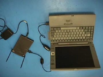
Click to zoom
Application Details
- Equipment Class
- PCB - PCS Licensed Transmitter
- Date of Grant
- Mar 22, 2001
- Application Purpose
- Original Equipment
- Date of Application
- Mar 22, 2001
- Equipment Note
- PCS CDMA Wireless Modem
- Frequency Range
- 1851.25000000 - 1908.75000000
- Company
- Qualcomm Technologies, Inc.
- Country
- United States
Documents & Files
Document Text
Text extracted from the exhibit documents filed with the FCC. Open a document above to read the original.
Users Manual
PCS Access Terminal Modem FCC Part 24 CertificationFCC ID: J9CHDR1 QUALCOMM ProprietaryPage 7-1 Exhibit 7. User Manual Hornet Access Terminal User's Guide80-H0494-1, Rev. ATable of Contents QUALCOMM ProprietaryRestricted Distribution - DO NOT COPYi Table of Contents 1. Introduction.................................................................................................1-1 1.1 Product Information.................................................................................1-1 1.2 Usage Agreement.....................................................................................1-4 2. External Connectors/Power Switch..........................................................2-1 2.1 Charging the battery.................................................................................2-2 2.2 Computer Connectivity............................................................................2-3 3. Modem LEDs...............................................................................................3-1 3.1 Power LED...............................................................................................3-1 3.2 Tx LED.....................................................................................................3-1 3.3 Rx LED.....................................................................................................3-1 3.4 Service LED.............................................................................................3-2 3.5 Modem Installation..................................................................................3-2 4. PC Configuration........................................................................................4-1 Table Of Contents80-H0494-1, Rev. APCS Access Terminal User's Guide iiRestricted Distribution - DO NOT COPYQUALCOMM Proprietary Hornet Access Terminal User's Guide80-H0494-1, Rev. AFigures QUALCOMM ProprietaryRestricted Distribution - DO NOT COPYiii Figures Figure 1-1 PCS Access Terminal...........................................................................................1-3 Figure 2-1 Modem End view................................................................................................2-1 Figure 2-2 Modem Side view................................................................................................2-2 Figure 3 Modem Installed on a laptop front view..................................................................3-3 Figure 4 Modem installed on a laptop side view...................................................................3-3 PCS Access Terminal User's Guide80-H0494-1, Rev. X1Introduction QUALCOMM ProprietaryRestricted Distribution - DO NOT COPY1-1 PCS CDMA Wireless Modem Users Guide 1. Introduction This document is a user guide for the PCS Wireless modem, or PCS Access Terminal. The wireless modem provides the fastest fully mobile wireless link available to the internet, at data rates of up to 2.4Mbps (peak data rate on the forward link). 1.1 Product Information • Dual receive chain for diversity support • Compact size : 7" x 4.5" x 0.8" • Lightweight : 12 ounces • Ethernet interface to host P.C. • RS-232 debug port. • Hardware support for USB (no software support at this time). Introduction80-H0494-1, Rev. AHornet Access Terminal User's Guide 1-2Restricted Distribution - DO NOT COPYQUALCOMM Proprietary • Internal battery provides 1 hour of continuous transmission on the reverse link. Total operating time / standby time figures are not yet available. • AC adapter for fixed operation / battery charging. • Cigarette lighter adapter for in car operation /battery charging. • ANSI J-STD-18 design goal. Note : This device contains no user serviceable parts, and shall only be opened by authorized Qualcomm personnel. The modem contains highly sophisticated electronics, which may be damaged if the modem is opened. The modem contains an internal lithium ion polymer battery, which can easily be damaged or cause damage if the modem is opened by unauthorized personnel. Caution The modem must be used in a configuration that ensures a minimum line-of-sight separation distance of 20cm (8 inch) is maintained at all times between the modem transmit antenna and any personnel. The transmit antenna location is shown in figure 1-1. Hornet Access Terminal User's Guide80-H0494-1, Rev. AIntroduction QUALCOMM ProprietaryRestricted Distribution - DO NOT COPY1-3 Tx antenna Figure 1-1 PCS Access Terminal Introduction80-H0494-1, Rev. AHornet Access Terminal User's Guide 1-4Restricted Distribution - DO NOT COPYQUALCOMM Proprietary 1.2 Usage Agreement The following describes the restrictions on the use of the HDR Access Terminal. The HDR System and its components are proprietary and confidential property of QUALCOMM and contain proprietary information . The end user agrees not to open or attempt to access the contents of the HDR System provided by QUALCOMM for the Customer Trial. The end user further agrees not to reverse engineer, decompile, translate or disassemble any component or software provided as part of the HDR System. QUALCOMM will utilize various means of securing the equipment that will make it evident to QUALCOMM if the integrity of the equipment has been compromised. These restrictions shall apply to all HDR Systems provided by QUALCOMM to the end user. The confidential nature of the HDR System, its components and hardware shall survive the termination of any agreements between the parties relating to confidentiality and/or the HDR System. Additionally, the end user agrees to provide written notification of these specific restrictions to all customers and other parties that receive the HDR System or any component thereof. The end user further assumes responsibility for enforcement of these restrictions upon any party that receives the HDR System or any component thereof directly or indirectly. Hornet Access Terminal User's Guide80-H0494-1, Rev. AExternal Connectors/Power Switch QUALCOMM ProprietaryRestricted Dist…
Text truncated - open the document above for the full version.
Attestation Statements
PCS Access Terminal Modem FCC Part 24 CertificationFCC ID: J9CHDR1 Exhibit 3. Attestation Statement The equipment, QUALCOMM model PCS Access Terminal Modem, is a CDMA wireless PCS modem, classified as a mobile transmitter as identified in FCC CFR47, Part 2.1091. The product is designed to operate at a granted level of 0.490 Watts E.I.R.P. The equipment complies with uncontrolled RF exposure environment requirement by the IEEE STD C95.1. and FCC OET Bulletin 65, Edition 97-01 August 1997. The data, data evaluation and equipment configuration represented herein for equipment certification are a true and accurate representation of the measurements of the sample’s radio frequency interference emissions characteristics as of the dates and at the times of the test under the conditions herein specified. This applies to all tests that do not require an Open Area Test Site (OATS) to perform. TUV Product Services performed tests that required an OATS site. Equipment Tested:PCS Access Terminal Modem Part 24 References:24.235 Frequency Stability 24.238 Emissions Limits Part Number:10-85893-1 Series Number:N1080DFDM Dates of Test:February 7, 2001, February 21, 2001 Test Performed by:John Forrester, Senior Engineer Senior EMC/Regulator Engineer Qualcomm Incorporated TÜV PRODUCT SERVICE 10040 Mesa Rim Road San Diego, CA 92121-2912 Phone 858 546 3999 FAX 858 546 0364 Report No. 100712-03 Page 2 of 11 Rev.No 1.0 Measurement Requirements (CFR 47 Part 2, Paragraph 2.1053 & Part 24, Paragraph 24.238 The measurements which follow were performed by TÜV Product Service. To the best of my knowledge these tests were conducted in accordance with the procedures outlined in Part 2 of the Commission's Rules and Regulations. The data presented below demonstrates compliance with the appropriate technical standards. _____________________________ Floyd R. Fleury EMC Manager
Cover Letter(s)
PCS Access Terminal Modem FCC Part 24 Certification FCC ID: J9CHDR1Cover Letters QUALCOMM ProprietaryPage 2-1 Exhibit 2. Cover Letters 2.1 Equipment Authorization Application for FCC ID J9CHDR1 TO: TCB, BABT Product Service 4855 Patrick Henry Drive, Building 6 Santa Clara, CA 95054 March 15, 2001 Re: Equipment Authorization Application for FCC ID: J9CHDR1 QUALCOMM herein submits the Application for Equipment Authorization (FCC Form 731) and Exhibits for Certification of a mobile transmitter unit with model name “PCS Access Terminal Modem”, FCC ID J9CHDR1, operating in PCS frequency band. Applicant:QUALCOMM, INC. 5775 Morehouse Drive San Diego, CA 92121-1714 Manufacture:QUALCOMM, INC. 5775 Morehouse Drive San Diego, CA 92121-1714 The equipment, QUALCOMM model PCS Access Terminal Modem, is a CDMA wireless PCS modem, classified as a mobile transmitter as identified in FCC CFR47, Part 2.1091. The application requests a grant power level of 0.490 W EIRP. John Forrester EMC/Regulatory Engineer Qualcomm Inc. Cover LettersFCC ID: J9CHDR1 PCS Access Terminal Modem FCC Part 24 Certification Page 2-2QUALCOMM Proprietary 2.2 Request of Confidentiality TO: TCB, BABT Product Service 4855 Patrick Henry Drive, Building 6 Santa Clara, CA 95054 March 15, 2001 Re: Request of Confidentiality Pursuant to Sections 0.457 and 0.459 of the Commission’s Rules, the Applicant hereby requests confidential treatment of the information accompanying this Application as outlined below: All schematics/block diagrams All parts lists The above materials contain trade secrets and proprietary information not customarily released to the public. The public disclosure of these matters might be harmful to the Applicant and provide unjustified benefits to its competitors. The Applicant understands that pursuant to Rule 0.457, disclosure of this Application and all accompanying documentation will not be made before the date of the Grant for this Application. John Forrester EMC/Regulatory Engineer QUALCOMM, INC.
External Photos
External PhotosFCC ID: J9CHDR1 PCS Access Terminal Modem FCC Part 24 Certification Page 9-2QUALCOMM Proprietary Exhibit 9. External Photos 9.1 Topside Appearance 9.2 Bottom Appearance PCS Access Terminal Modem FCC Part 24 CertificationFCC ID: J9CHDR1 QUALCOMM ProprietaryPage 9-3 9.3 Modem Connected to Laptop Computer 9.4 Modem Mounted on Desktop External PhotosFCC ID: J9CHDR1 PCS Access Terminal Modem FCC Part 24 Certification Page 9-4QUALCOMM Proprietary 9.5 Antennas Retracted Position
ID Label/Location Info
PCS Access Terminal Modem FCC Part 24 CertificationFCC ID: J9CHDR1 Exhibit 8. FCC Identifier Label The FCC identifier label is located on the bottom side of the modem. Figure 8–1. FCC Identifier label Figure 8–2. Zoom-in FCC Identifier DEC XXXXXXXXXXX HEX XXXXXXXX +8.4 VDC, 1.0A FCC ID: J9CHDR1 d PCS Access Terminal Modem QUALCOMM INC. AW15-H0436-1, REV X1 ARTWORK, FCC LABEL DEC XXXXXXXXXXX HEX XXXXXXXX +8.4 VDC, 1.0A FCC ID: J9CHDR1 d 1.600" 0 . 7 0 0 " PCS Access Terminal Modem
Internal Photos
PCS Access Terminal Modem FCC Part 24 CertificationFCC ID: J9CHDR1 Exhibit 10. Internal Photos 10.1 Internal Front with shields 10.2 Internal Rear with shields RF Board Digital Board RF Board Digital Board Internal PhotosFCC ID: J9CHDR1 PCS Access Terminal Modem FCC Part 24 Certification 10.3 Internal Front with no shield RF Board Digital Board PCS Access Terminal Modem FCC Part 24 CertificationFCC ID: J9CHDR1 10.4 Internal Rear with no shield RF Board Digital Board RELEASED 10/23/2000 INTERNAL USE ONLY RELEASED 10/23/2000 INTERNAL USE ONLY RELEASED 11/14/2000 INTERNAL USE ONLY RELEASED 11/14/2000 INTERNAL USE ONLY RELEASED 11/14/2000 INTERNAL USE ONLY RELEASED 11/14/2000 INTERNAL USE ONLY RELEASED 11/14/2000 INTERNAL USE ONLY RELEASED 11/14/2000 INTERNAL USE ONLY
Operational Description
PCS Access Terminal Modem FCC Part 24 CertificationFCC ID: J9CHDR1 QUALCOMM ProprietaryPage 4-1 Exhibit 4. Product Overview (Part 2.1033) 4.1 Technical Description The Access Terminal Modem operates through the PCS wireless infrastructure network. The modem provides the fastest fully mobile wireless link available from a PC to the internet, at data rates of up to 2.4Mbps. The unit incorporates two antennas two improve receiver performance through antenna diversity. One of the antennas also acts as the transmit antenna for communication with base-stations. The modem can be attached to a laptop computer with velcro for mobile internet use. The modem communicates with the PC via an ethernet or USB cable. The modem also incorporates a lithium-ion battery for use with a laptop when AC power is unavailable. 4.2 Address of Manufacturer and Applicant 2.1033 (c) (1) Manufacturer: Qualcomm Incorporated 5775 Morehouse Drive San Diego, CA 92121 Telephone: (858) 587-1121 Applicant: QUALCOMM, INC. 5775 Morehouse Dr. San Diego, CA 92121 Telephone: (858) 587-1121 4.3 FCC Identifier 2.1033 (c) (2) The FCC identifier is: J9CHDR1 4.4 User Manual 2.1033 (c) (3) See Exhibit 7: User Manual 4.5 Types of Emissions 2.1033 (c) (4) 1M25F9WF1D wideband data signal 4.6 Frequency Range 2.1033 (c) (5) The frequency range of terminal modem is the Personal Communications Services (PCS) bands, 1851.25 – 1908.75 MHz for transmission and 1931.25 – 1988.75 MHz for reception. The channel spacing is 1.25 MHz for CDMA. Product Overview (Part 2.1033)FCC ID: J9CHDR1 PCS Access Terminal Modem FCC Part 24 Certification Page 4-2QUALCOMM Proprietary 4.7 Operating Power Levels 2.1033 (c) (6) The equipment supports Class 3 Mobile Station Power Class, and its power output capability is reported to the Land Station via Station Class Mark. 4.8 Maximum Output Power 2.1033 (c) (7) The equipment is within the limited 2 watts E.I.R.P.peak power of CFR 47 Part 24.232 (b) and is able to limit the output power to the minimum necessary for successful communications. The maximum peak output power the modem is designed to operate at is a granted power level of 0.490 W EIRP. 4.9 DC Supply and Current Range 2.1033 (c) (8) The equipment is powered by an AC power supply that converts to 12Vdc. The specified DC operating range is 6-8.5 Vdc. 4.10 List of Semiconductor Active Devices 2.1033 (c) (10) See exhibit 13: Parts List 4.11 Circuit Diagram 2.1033 (c) (10) See exhibit 12 Schematics 4.12 Transmitter Adjustment Procedure 2.1033 (c) (9) All frequency adjustments are set at the factory and there are no frequency field adjustments for this product. Under digital mode, frequency is locked to the base station and controlled by VCTCXO adjustments to offset any possible errors. 4.13 Frequency Stability Device 2.1033 (c) (10) A temperature compensated, crystal oscillator (TCXO) is employed as a frequency reference for all of the transceiver local oscillators. This crystal oscillator is specified to remain within +/- 2.5 ppm over temperature and voltage variations. The lock status indicator of all synthesizers is monitored by the microprocessor and an out of lock condition will inhibit transmission. The mobile receiver monitors the received signal and adjusts the frequency of the TCXO, this corrects any errors between the mobile frequency and the base station transmitter. The mobile is locked to the base station. 4.14 Spurious Radiation Suppression Devices 2.1033 (c) (10) Reference Designator Part NameFunction FL2duplexer Provides protection against transmitter spurious emissions and receiver local oscillator leakage FL 6TX Ceramic filter Provides suppression of spurious energy and transmitter harmonics 4.15 Drawing of Equipment Identification Plate or Label 2.1033 (c) (11) See Exhibit 8: Identifier Label: PCS Access Terminal Modem FCC Part 24 CertificationFCC ID: J9CHDR1 QUALCOMM ProprietaryPage 4-3 4.16 Photographs 2.1033 (c) (12) See Exhibit 9: Photographs Product Overview (Part 2.1033)FCC ID: J9CHDR1 PCS Access Terminal Modem FCC Part 24 Certification Page 4-4QUALCOMM Proprietary 4.17 Modulation Technique 2.1033 (c) (13) The CDMA mode is described in the following pages from the HDR Air Interface Specification. The justification for the CDMA bandwidth of 1.25 MHz is that the chip rate is 1.228 MHz (see page 6-10 of IS-95 ). When we look 3 dB down from the signal we find 1.25 MHz. Channel spacing is normally set at this 1.25 MHz. PCS Access Terminal Modem FCC Part 24 CertificationFCC ID: J9CHDR1 QUALCOMM ProprietaryPage 4-5 Product Overview (Part 2.1033)FCC ID: J9CHDR1 PCS Access Terminal Modem FCC Part 24 Certification Page 4-6QUALCOMM Proprietary PCS Access Terminal Modem FCC Part 24 CertificationFCC ID: J9CHDR1 QUALCOMM ProprietaryPage 4-7 Product Overview (Part 2.1033)FCC ID: J9CHDR1 PCS Access Terminal Modem FCC Part 24 Certification Page 4-8QUALCOMM Proprietary PCS Access Terminal Modem FCC Part 24 CertificationFCC ID: J9CHDR1 QUALCOMM ProprietaryPage 4-9 4.18 Test Data 2.1033 (3) (14) See Exhibit 7: Measurement Results and Exhibit 11: Radiated Test Report 4.19 RF Block Diagram See Exhibit 12: Block Diagram
RF Exposure Info
PCS Access Terminal Modem FCC Part 24 CertificationFCC ID: J9CHDR1 QUALCOMM ProprietaryPage 6-1 Exhibit 6. RF Exposure Table 6-1 gives a summary of the expected radiation exposure levels versus distance from the transmitter antenna using equation. The analysis was performed in reference to FCC OET Bulletin 65. The maximum EIRP power used for the MPE calculation incorporates 1 dB of calibration error and the worst case peak gain to represent the worst case transmit power. Page 1 of the Access Terminal Modem user manual specifies a minimum distance of 15 cm (6 in) separation distance between the user and the unit to insure RF safety requirements are satisfied. Typical use of the modem involves distances exceeding 20 cm, thus further reducing the RF exposure level. Table 6–1. RF exposure level analysis Reference: FCC OET Bulletin No. 65, 1985 EUT Specifics Max. Conducted Power = 251.2 mW = 24.00 dBm Calibration Error Tolerance = 1.0 dB Max. Antenna Gain = 2.9 dBi Maximum EIRP = 617 mW = 27.90 dBm Far-Field Power Density Calculations Free Space:P.d = EIRP/(4 * pi * r^2) 100% Ground Reflection:P.d = EIRP/( pi * r^2) 1997 FCC Uncontrolled MPE = 1.0 mW/cm^2 FCC Uncontrolled MPE Minimum Safe Distance Frequency (MHz)Wavelength (cm) FCC MPE (mW/cm^2) Distance to Free Space MPE (cm) Distance to 100% Ground Reflection MPE (cm) 1830 16.391.0007.0014.01 1880 15.961.0007.0014.01 1908 15.721.0007.0014.01 MPE at Minimum Distance Specified by Hornet User Manual Frequency (MHz)Wavelength (cm)Distance (cm) Free Space MPE (mW/cm^2) 100% Ground Reflection MPE (mW/cm^2) 1830 16.3915.0000.220.87 1880 15.9615.0000.220.87 1908 15.7215.0000.220.87
Test Report
PCS Access Terminal Modem FCC Part 24 CertificationFCC ID: J9CHDR1 QUALCOMM ProprietaryPage 5-1 Exhibit 5. Measurement Results 5.1 Transmitter RF Power Output 5.1.1 Conducted RF Power Output The conducted RF power output is tested per Part 2.1046(a). The RF output power was measured using a HP 8594E Spectrum Analyzer that has the CDMA spectrum analyzer option. The antenna cable of the equipment is terminated to a 50 ohms resistive load of the Spectrum Analyzer. The nominal maximum power from the CDMA phone module is 251mW or 24 dBm. The unit was configured to transmit as close to 24 dBm conducted power as the test software would allow. Production units incorporate a precision calibration process to achieve 24 dBm conducted power for all channels in the transmit band. Taking account the cable loss, the power level measured represents the power from the RF port of the equipment. Table 5-1 and Fig. 5-1 to Fig. 5-3 show the measured data and waveform. Table 5–1. Conducted RF power output (W) Transmission ChannelCarrier frequency (MHz)RF power in CDMA mode 251851.250.243 60018800.245 11751908.750.235 Figure 5–1. Power level on channel 25 Measurement ResultsFCC ID: J9CHDR1 PCS Access Terminal Modem FCC Part 24 Certification Page 5-2QUALCOMM Proprietary Figure 5–2. Power level on channel 600 Figure 5–3. Power level on channel 1175 5.1.2 Radiated RF Power Output The radiated power was measured using the method of substitution at an open air test side (TUV). Test code was used to configure the unit to transmit at a power level higher then the desired grant level of 0.490 W EIRP to represent the worst case transmit harmonic emissions from the unit. Refer to TUV Product Service Test Report for the measured EIRP for the high, mid, and low channels. PCS Access Terminal Modem FCC Part 24 CertificationFCC ID: J9CHDR1 QUALCOMM ProprietaryPage 5-3 5.2 Occupied Bandwidth Occupied Bandwidth of the equipment was tested pursuant to FCC Part 2.1049. The measurement was conducted using HP 8594E spectrum analyzer with CDMA feature option. The measured data is shown in Table 5-4 and Fig.5-4 through Fig.5-6. Table 5–2. Occupied Bandwidth (99%) Transmission ChannelCarrier frequency (MHz)Occupied bandwidth (MHz) 251851.251.247 60018801.247 11751908.751.266 Figure 5–4. Occupied bandwidth on channel 25 Measurement ResultsFCC ID: J9CHDR1 PCS Access Terminal Modem FCC Part 24 Certification Page 5-4QUALCOMM Proprietary Figure 5–5. Occupied bandwidth on channel 600 Figure 5–6. Occupied bandwidth on channel 1175 PCS Access Terminal Modem FCC Part 24 CertificationFCC ID: J9CHDR1 QUALCOMM ProprietaryPage 5-5 5.3 Conducted Spurious Emission Conducted emission from the equipment was tested pursuant to FCC Part 2.1046 and 24.238. The emissions were tested in reference to the limit specified by Part 24.238. Power of any emission shall be atteunated below the transmitter power by at least: dBmwattsP13)(log1043−=+. For measurements of the transmit harmonics, a broad band high pass filter was used to attenuate the fundamental transmit spike to prevent overdriving of the spectrum analyzer front end. Measurements were conducted using a HP 8593EM spectrum analyzer. The spectrum analyzer has the capability to load cable factors and antenna gain factors so that the spectrum analyzer’s output compensates for external attenuation factors. The spectrum analyzer was loaded with cable factors from 10 kHz to 19 GHz. A peak antenna gain of 2.9 dBi was used across the entire spectrum. The resulting plots shown in Fig 5-7 through 5-12 thus represent maximum EIRP values. The plots are broken up into two plots for each frequency: 0 Hz to 2.7 GHz, and 2.7 GHz to 18 GHz. No emission within 10 dB of the specified limit was observed. The measurement results are shown in the Table 5-5 through Table 5-7 and Fig.5-7 through Fig.5-12. Table 5–3. Conducted spurious emission at low-band (channel 25) HarmonicsFrequency (MHz) Measured level (dBm) Limit (dBm) Measurement attenuation 11851.2523.85-40 23702.50-68.8-130 35553.75-73.2-130 47405.00-52.1-130 59256.25-82-130 611107.50<-81-130 712958.75<-75-130 814810.00<-77-130 916661.25<-76-130 1018512.50<-76-130 Table 5–4. Conducted spurious emission at mid-band (channel 600) HarmonicsFrequency (MHz) Measured level (dBm) Limit (dBm) Measurement attenuation 11880.0023.85-40 23760.00-73.8-130 35640.00-71.8-130 47520.00-43.2-130 Measurement ResultsFCC ID: J9CHDR1 PCS Access Terminal Modem FCC Part 24 Certification Page 5-6QUALCOMM Proprietary 59400.00<-81-130 611280.00<-81-130 713160.00<-76-130 815040.00<-78-130 916920.00<-77-130 1018800.00<-76-130 Table 5–5. Conducted spurious emission at high-band (channel 1175) Harmonics Frequency (MHz) Measured level (dBm) Limit (dBm) Measurement attenuation 11908.7523.62-40 23817.50-77.8-130 35726.25-69-130 47635.00-47.2-130 59543.7582-130 611452.50<-78-130 713361.25<-78-130 815270.00<-77-130 917178.75<-76-130 1019087.50<-76-130 Figure 5–7. Overall profile under channel 25 (0-2.9GHz) PCS Access Terminal Modem FCC Part 24 CertificationFCC ID: J9CHDR1 QUALCOMM ProprietaryPage 5-7 Figure 5–8. Overall profile under channel 25 (2.8-20GHz) Figure 5–9. Overall profile under channel 600 (0-2.9GHz) Measurement ResultsFCC ID: J9CHDR1 PCS Access Terminal Modem FCC Part 24 Certification Page 5-8QUALCOMM Proprietary Figure 5–10. Overall profile under channel 600 (2.8-20GHz) Figure 5–11. Overall profile under channel 1175 (0-2.9GHz) PCS Access Terminal Modem FCC Part 24 CertificationFCC ID: J9CHDR1 QUALCOMM ProprietaryPage 5-9 Figure 5–12. Overall profile under channel 1175 (2.8-20GHz) 5.4 Radiated Spurious Emissions Refer to Exhibit 10: TUV Product Service Test Report. Measurement ResultsFCC ID: J9CHDR1 PCS Access Terminal Modem FCC Part 24 Certification Page 5-10QUALCOMM Proprietary 5.5 Frequency Stability Frequency stability of the equipment versus temperature and power supply change was tested pursuant to FCC Part 2.1055. Measurement was conducted in CDMA channel 600 transmitting mode wit…
Text truncated - open the document above for the full version.
Test Setup Photos
PCS Access Terminal Modem FCC Part 24 CertificationFCC ID: J9CHDR1 QUALCOMM ProprietaryPage 5-11 5.6 Measurement Procedures 5.6.1 List of Test Equipment 1. Computer with Netscape to interact with test software. 2. Spectrum Analyzers HP8593EM, S/N 3643A0680 HP8594E with CDMA spectrum analyzer option, S/N 3733U03464 5.6.2 Measurement Procedures 5.6.2.1 Conducted RF Power Output Definition - The output power rating of the transmitter is the power available at the output terminal of the transmitter when the terminal is connected to the normal load. Method of Measurement - The transmitter output carrier power with CDMA modulation was measured using an HP 8594E spectrum analyzer with the CDMA feature option. The measurement setup diagram is shown in Fig. 4-1. Minimum Standard - The transmitter output power shall be maintained within range of –4dB to 2dB. HP 8594E Spectrum Analyzer AC Power Controller PC EUT CDMA Tx code RF output Figure 5–13. Measurement setup for conducted RF power 5.6.2.2 Radiated RF Power Output Refer to TUV Product Service Test Report. 5.6.2.3 Occupied Bandwidth Definition - The occupied bandwidth is defined as the spectrum noise produced at discrete frequency separations from the carrier due to all sources of unwanted noise within the transmitter in a modulated condition. Method of Measurement - Use the spectrum analyzer and measure the CDMA spectrum, modulate with full rate. The measurement setup diagram is shown in Fig. 4-2. Minimum Standard - The mean power of emissions from the transmitter with modulated carrier shall be attenuated below the mean power of the modulated carrier in accordance with the following. Measurement ResultsFCC ID: J9CHDR1 PCS Access Terminal Modem FCC Part 24 Certification Page 5-12QUALCOMM Proprietary At any frequency outside the licensed PCS frequency block, the power of any emission shall be attenuated below the transmitter power (P) by at least )(log 1043P + dB, in which, P is mean output power in Watts. As the mean power of the terminal modem is approximately 24 dBm, the spurious emission would be 35 dB below the transmission power, equivalent to a absolute limit of –13dBm. 3. For the 1 MHz bands immediately outside and adjacent to the frequency block a resolution bandwidth of at least one percent of the emission bandwidth of the fundamental emission of the transmitter may be employed. The emission bandwidth is defined as the width of the signal between two points, one below the carrier center frequency and one above the carrier center frequency, outside of which all emissions are attenuated at least 26 dB below the transmitter power. HP 8594E Spectrum Analyzer AC Power Controller PC EUT CDMA Tx code RF output Figure 5–14. Measurement setup for Occupied Bandwidth 5.6.2.4 Conducted Spurious Emissions Definition - The conducted harmonic and spurious emissions are emissions at the antenna terminals at a frequency or frequencies that are outside the authorized bandwidth of the transmitter. Method of Measurement - The transmitter shall be modulated with CDMA at full rate. The measurement shall be made with a spectrum analyzer from the lowest radio frequency generated in the equipment to the 10th harmonic of the carrier. The measurement setup diagram is shown in Fig. 4-3. Minimum Standard - Conducted harmonic and spurious emissions shall be attenuated below the level of emissions of the carrier frequency by at least )(log 1043P + dB, in which, P is mean output power in Watts. HP 8594E Spectrum Analyzer DC Power Controller PC EUT CDMA Tx code RF output Figure 5–15. Measurement setup for conducted spurious emissions 5.6.2.5 Radiated Spurious emissions Definition - The radiated spurious emissions are emissions from the terminal modem with the attached antenna fully extended. The radiated spurious emissions include those emissions radiated from the attached antenna as well as the equipment cabinet and attached cables. PCS Access Terminal Modem FCC Part 24 CertificationFCC ID: J9CHDR1 QUALCOMM ProprietaryPage 5-13 Method of Measurement - The measurement shall be conducted at standard radiation test site with a search antenna, which is movable vertically and is rotatable 90 degrees for vertically and horizontally polarized signals. Refer to TUV Product Service Test Report for measurement setup Minimum Standard - Radiated spurious emissions shall be attenuated below the maximum level of emission of the carrier frequency by at least )(log 1043P+ dB, in which, P is mean output power in Watts. 5.6.2.6 Frequency Stability Definition - The frequency stability is the ability of the transmitter to maintain an assigned carrier frequency against variation in ambient temperature and power supply. Method of Measurement - Use the spectrum analyzer to sample the transmitter RF output signal and measure its frequency under each specific temperature and power supply condition. Vary the ambient temperature from -30 to +60 °C, and also vary the DC supply voltage to the equipment from 11.2 to 16.8 V at each temperature. The measurement setup diagram is shown in Fig. 4-4. Minimum Standard - The transmitter carrier frequency shall be maintained within ± 2.5 ppm. HP 8594E Spectrum Analyzer AC Power Controller PC EUT CDMA Tx code RF output Figure 5–16. Measurement setup for frequency stability TÜV PRODUCT SERVICE 10040 Mesa Rim Road San Diego, CA 92121-2912 Phone 858 546 3999 FAX 858 546 0364 Report No. 100712-03 Page 10 of 11 Rev.No 1.0 Photograph of Test Setup TÜV PRODUCT SERVICE 10040 Mesa Rim Road San Diego, CA 92121-2912 Phone 858 546 3999 FAX 858 546 0364 Report No…
Text truncated - open the document above for the full version.
Contact Information
Applicant
Paul Guckian(Vice President, Regulatory Engineering)
Test Firm
TUV AmericaJames Owen
Technical Specifications
| # | Rule Parts | Frequency Range | Power Output | Emission | Tolerance |
|---|---|---|---|---|---|
| 1 | 24E | 1.85 GHz - 1.91 GHz | 490.00 mW | 1M25F9W | 0.0002500000 % |
Other Applications from Qualcomm Technologies, Inc.
J9C-M2X75
Aug 13, 2024Module
Equipment Class
CBE - Citizens Band End User DevicesJ9C-M2X72
Aug 13, 2024Module
Equipment Class
PCB - PCS Licensed Transmitter
J9C-QCNCM825
Aug 26, 2023Qualcomm WiFi 7/BT Combo module
Equipment Class
6CD - 15E 6 GHz Low Power Dual Client
J9C-QCNCM865
Apr 04, 2023Qualcomm WiFi 7/BT Combo module
Equipment Class
NII - Unlicensed National Information Infrastructure TX
J9CQCARD7280N
Nov 07, 2022QCARD7280
Equipment Class
DTS - Digital Transmission System