J9CIEMEVDOInternet Everything Module
Qualcomm Technologies, Inc.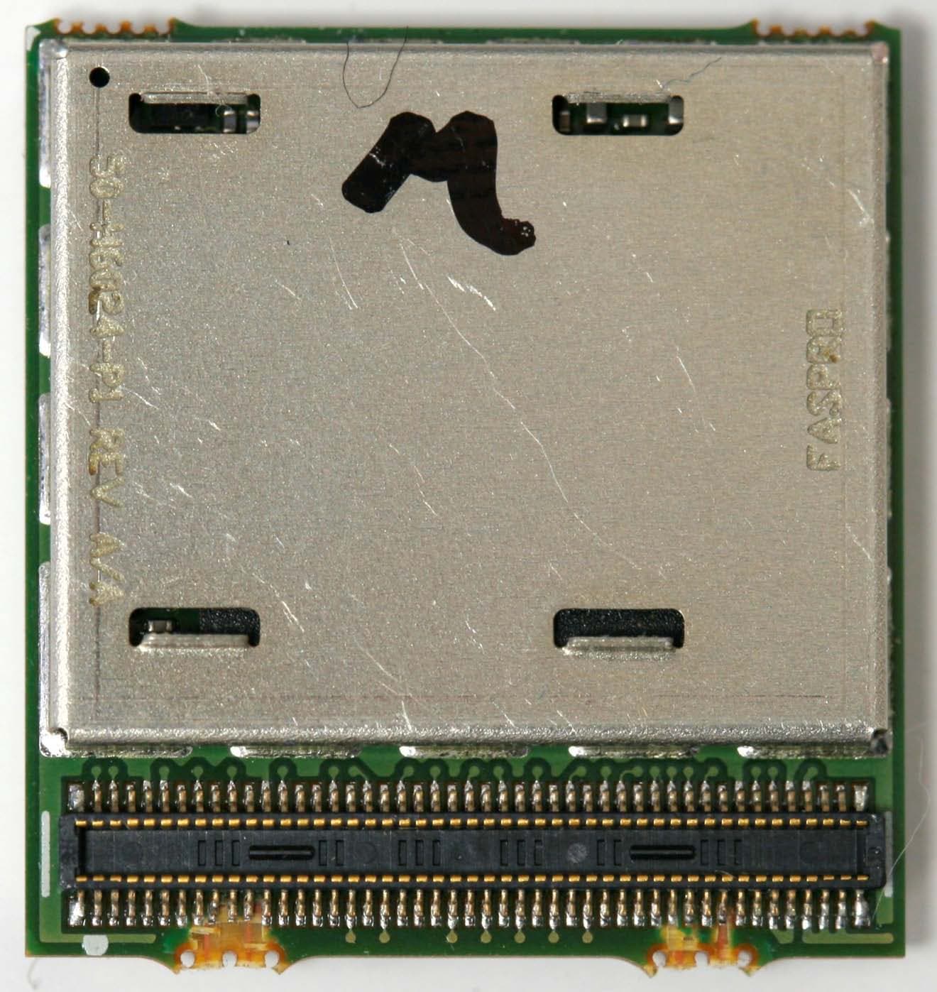
Click to zoom
Application Details
- Equipment Class
- PCB - PCS Licensed Transmitter
- Date of Grant
- Feb 20, 2011
- Application Purpose
- Original Equipment
- Date of Application
- Feb 20, 2011
- Equipment Note
- Internet Everything Module
- Frequency Range
- 1851.25000000 - 1908.75000000
- Company
- Qualcomm Technologies, Inc.
- Country
- United States
Documents & Files
Document Text
Text extracted from the exhibit documents filed with the FCC. Open a document above to read the original.
Users Manual
IEM 1x/EVDO Development Kit User Guide 80-XXXXX-1 Re v. A Mark Carter January 2011 1 #Section Page 1Introduction3 2 Getting Started4 3CableConnections6 4PowerSupply Connection8 5Module Powering Up / Down10 6Telephone & Data Call Testing11 7Standards 12 8Regulatory Compliance13 Front Back Table of Contents 2 Introduction •The IEM development kit enables telephone & Data functionality with the entire family of IEM modules. •The Kit includes: –IEM Module –Test Nest fixture –RF Antenna –Battery Pack –QCT Software –Handset –External Power Cable – Micro USB cable 3 Getting Started •Apply Thermal Grease to pad 4 Thermal Grease Insert Module •Insert the IEM module into the Test Nest fixture using the 90 pin connector with the JTAG connector still attached. 5 WMD Module Cable Connections •Connect the internal RF cable 6 RF Cable Handset Jack Micro USB Te s t Jumpers RUIM / SIM Slot 1.3M Pixel Camera (1x) Headset Jack Speaker Cable Connections •Connect the external antenna •Connect the handset 7 Handset Plug In 3M Pixel Camera (UMTS & EVDO) RF Antenna & GPS/Modem (1X) GPS (UMTS) Bluetooth Power Supply Connections •Connect the power supply cable & or plug in battery connector •Set power supply voltage to 3.7 volts – no battery •Battery will charge if power supply is set to 5 volts 8 Micro USB PWR Cable Battery Connector Power Supply Connections -Alt •Alternate power connection to replace battery •Set power supply voltage to 3.7 volts 9 Micro USB Power/Data Cable Alt Power Connector Alt Power Cable Module Power Up •Now power up the module by pressing the pwrbutton on the keypad •LCD and backlight turn on 10 PWR button Telephone & Data Call Testing •Now the Module is ready for basic telephone & Data call functionality •Use keypad or USB/RF interfaces to initiate and end voice or data calls 11 Standards The IEM module conforms to the following standards requirements: •CDMA –TIA/EIA IS-98E (CDMA2000 1x) –IS-856 Release A (1xEV-DO) •FCC –47 CFR Part 1 –RF radiation exposure limits –47 CFR Part 2 –Equipment authorization –47 CFR Part 15 –Intentional and unintentional radiators –47 CFR Part 22 –Cellular – 47 CFR Part 24 -PCS •Open Device Initiative Certification w/ VZW 12 Regulatory Compliance Safety Warnings Do not operate the IEM module in the following environments: •In active blasting areas. •In potentially explosive environments such as refueling points, fuel depots or chemical plants. •Near medical equipment, especially life support equipment that might be susceptible to radio interference. •In an aircraft. –The IEM module transmissions could interfere with aircraft electrical and communication systems. Like cell phones, using the IEM module in an aircraft is illegal in some jurisdictions. – If cell phone usage is permitted while the aircraft is on the ground, normal IEM module operation is permitted as well. 13 Regulatory Compliance The IEM module has been approved for mobile applications in the United States. •Maintain at least 20 cm separation between the antennas and the user’s body. •Maximum antenna gain (including cable loss): –Cellular band < 3 dBi –PCS band < 3 dBi •A label with the following (or similar) statement must be attached to the host end product: This device contains TxFCC ID:J9CIEMEVDO. •Note: This equipment has been tested and found to comply with the limits for a Class B digital device, pursuant to Part 15 of the FCC rules. These limits are designed to provide reasonable protection against harmful interference in a residential installation. This equipment generates, uses and can radiate radio frequency energy and, if not installed and used in accordance with the instructions, may cause harmful interference to radio communications. However, there is no guarantee that interference will not occur in a particular installation. If this equipment does cause harmful interference to radio or television reception, 14 Regulatory Compliance which can be determined by turning the equipment off and on, the user is encouraged to try to correct the interference by one or more of the following measures: •Reorient or relocate the receiving antenna. •Increase the separation between the equipment and receiver. •Connect the equipment into an outlet on a circuit different from that to which the receiver is connected. • Consult the dealer or an experienced radio/TV technician to help. •Changes or modifications not expressly approved by the party responsible for compliance could void the user’s authority to operate the IEM module. 15 Internet of Everything Module (IEM) Installation and Collocation Guidelines The following provides module installation guidelines for devices to be authorized for use with the IEM6085 through a FCC Class I Permissive Change process in accordance with FCC procedures, for the following installation host configurations. 1)The IEM6085 can be installed as a standalone transmitterin devices meeting the following conditions: –Fixed-mount or mobile host devices † where a minimum of 20 cm separation distance is provided between the transmitting antenna and the end user that can be installed without a Class Ior Class IIPermissive Changeprocess. –Portable hosts in accordance with KDB Publication 447498 * through a ClassII Permissive Changeor new FCC certification. 2)The IEM6085 can be installed with collocated transmission devicesfor fixed and mobile host devices approved under FCC ID J9CIEMEVDO through a Class I Permissive Changeprocess. The collocated transmitters must meet the technical requirements defined in Section 2. Mobile collocation is allowed without a Class I or Class II FCC process. • † Mobile equipment, as defined in CFR 47 §2.1091(b). Fixed-mount hosts are non-mobile equipment that are either fixed in place or large equipment that is not easily moved. • * KDB = Knowledge Database; KDB Publication 447498 D01 is the FCC procedure Mobile and Portable Device, RF Exposure Procedures and Equipment Authorization Policies. 16 17 For equipment in which the RF exposure classifi…
Text truncated - open the document above for the full version.
Cover Letter(s)
Federal Communications Commission 7435 Oakland Mills Road Columbia MD 21046 Subject: Request for Confidentiality FCC ID: J9CIEMEVDO To Whom It May Concern: Pursuant to the provisions of Sections 0.457 and 0.459 of the Commission’s rules (47 CFR §§ 0.457, 0.459), we are requesting the Commission to withhold the following attachments as confidential document from public disclosure indefinitely. Schematic Diagram Block Diagram Parts List Above mentioned document contains detailed system and equipment description are considered as proprietary information in operation of the equipment. The public disclosure of above documents might be harmful to our company and would give competitor an unfair advantage in the market. In additional to above mentioned documents, pursuant to Public Notice DA 04-1705 of the Commission’s policy, in order to comply with the marketing regulations in 47 CFR §2.803 and the importation rules in 47 CFR §2.1204, while ensuring that business sensitive information remains confidential until the actual marketing of newly authorized devices. We are requesting the commission to grant short-term confidentiality request for 180 days on the following attachments: External Photos Internal Photos User Manual It is our understanding that all measurement test reports, FCC ID label format and correspondent during the certification review process cannot be granted as confidential documents and those information will be available for public review once the grant of equipment authorization is issued. Best Regards Paul Guckian VP of Engineering Qualcomm Inc. 01/24/2011
Cover Letter(s)
Applicant/Grantee Qualcomm INC. FCC ID: J9CIEMEVDO Section 15.212 Modular Transmitters Request for Modular Approval Request for Limited Modular Approval Requirements EUT Conditions Comply (Y/N) Single Modular Approval Requirements 1 The radio elements of the modular transmitter must have their own shielding. The physical crystal and tuning capacitors may be located external to the shielded radio elements. The IEM module is fully shielded to prevent interference between the device and the module (See external photos in Exhibit 10). yes 2 The modular transmitter must have buffered modulation/data inputs (if such inputs are provided) to ensure that the module will comply with Part 15 requirements under conditions of excessive data rates or over-modulation. The buffer is provided through USB connection. See Exhibit 5 for details. yes 3 The modular transmitter must have its own power supply regulation. The IEM module has its own power supply regulation through the PMIC chip. yes 4 The modular transmitter must comply with the antenna and transmission system requirements of Sections 15.203, 15.204(b) and 15.204(c). The antenna must either be permanently attached or employ a “unique” antenna coupler (at all connections between the module and the antenna, including the cable). The “professional installation” provision of Section 15.203 is not applicable to modules but can apply to limited modular approvals under paragraph (b) of this section. The IEM module has unique antenna connectors. Antenna gain information is listed in the user’s manual and shall not be exceeded. yes 5 The modular transmitter must be tested in a stand-alone configuration, i.e., the module must not be inside another device during testing for compliance with Part 15 requirements. Unless the transmitter module will be battery powered, it must comply with the AC line conducted requirements found in Section 15.207. AC or DC power lines and data input/output lines connected to the module must not contain ferrites, unless they will be marketed with the module (see Section 15.27(a)). The length of these lines shall be the length typical of actual use or, if that length is unknown, at least 10 centimeters to insure that there is no coupling between All tests reported in this application were performed on a stand-alone basis. yes the case of the module and supporting equipment. Any accessories, peripherals, or support equipment connected to the module during testing shall be unmodified and commercially available (see Section 15.31(i)). 6 The modular transmitter must be equipped with either a permanently affixed label or must be capable of electronically displaying its FCC identification number. (A) If using a permanently affixed label, the modular transmitter must be labeled with its own FCC identification number, and, if the FCC identification number is not visible when the module is installed inside another device, then the outside of the device into which the module is installed must also display a label referring to the enclosed module. This exterior label can use wording such as the following: “Contains Transmitter Module FCC ID: XYZMODEL1” or “Contains FCC ID: XYZMODEL1.” Any similar wording that expresses the same meaning may be used. The Grantee may either provide such a label, an example of which must be included in the application for equipment authorization, or, must provide adequate instructions along with the module which explain this requirement. In the latter case, a copy of these instructions must be included in the application for equipment authorization. (B) If the modular transmitter uses an electronic display of the FCC identification number, the information must be readily accessible and visible on the modular transmitter or on the device in which it is installed. If the module is installed inside another device, then the outside of the device into which the module is installed must display a label referring to the enclosed module. This exterior label can use wording such as the following: “Contains FCC certified transmitter module(s).” Any similar wording that expresses the same meaning may be used. The user manual must include instructions on how to access the electronic display. A copy of these instructions must be included in the application for equipment authorization. Please refer to the FCC ID information in Exhibit 8. yes 7 The modular transmitter must comply with any specific rules or operating requirements that ordinarily apply to a complete transmitter and the manufacturer must provide adequate instructions along with the module to explain any such requirements. A copy of these instructions must be included in the The IEM module complies with all of relevant FCC requirements (See Exhibit 2, 3 and 4 for the test results and MPE analysis report), and the adequate instructions to keep the compliance have been provided in the User’s Guide (See Exhibit 11). yes application for equipment authorization. 8 The modular transmitter must comply with any applicable RF exposure requirements in its final configuration. The IEM module will be installed in a host product where the transmitting antenna can provide 20 cm separation distance to the body of user. Installation of this module in a portable configuration is not allowed unless proper equipment authorization has been obtained. See Exhibit 4 for MPE analysis yes A limited modular approval may be granted for single or split modular transmitters that do not comply with all of the above requirements, e.g., shielding, minimum signaling amplitude, buffered modulation/data inputs, or power supply regulation, if the manufacturer can demonstrate by alternative means in the application for equipment authorization that the modular transmitter meets all the applicable Part 15 requirements under the operating conditions in which the transmitter will be used. Limited modular approval also may be granted in those instances where compliance with RF exposure rules is demonstra…
Text truncated - open the document above for the full version.
Cover Letter(s)
Date: June 23, 2008 Compliance Certification Services Certification Division 47173 Benicia Street Fremont, CA 94538, USA To whom it may concern: I, the undersigned, hereby authorize Ms. Claire Hoque/Application Examiner of Compliance Engineering Services, Inc., d.b.a. Compliance Certification Services and hereafter referred to as CCS, to act on our behalf in all manners relating to application for equipment authorization, including signing of all documents relating to these matters. Any and all acts carried out by Ms. Claire Hoque of CCS on our behalf shall have the same effect as acts of our own. I, the undersigned, hereby certify that we are not subject to a denial of federal benefits, that includes FCC benefits, pursuant to Section 5301 of the Anti-Drug Abuse Act of 1988, 21 U.S.C. 853(a). In authorizing CCS as our agent, we still recognize that we are responsible to: a) comply with the relevant provisions of the certification program; b) make all necessary arrangements for the conduct of the evaluation, including provision for examining documentation and access to all areas, records (including internal audit reports) and personnel for the purposes of evaluation (e.g. testing, inspection, assessment, surveillance, reassessment) and resolution of complaints; c) make claims regarding certification only in respect of the scope for which certification has been granted; d) do not use our product certification in such a manner as to bring the Certification Division into disrepute and not make any statement regarding our product certification which the Certification Division may consider misleading or unauthorized; e) upon suspension or cancellation of certification, discontinue use of all advertising matter that contains any reference thereto and return any certification documents as required by the Certification Division; f) use certification only to indicate the products are certified as being in conformity with specified standards; g) endeavor to ensure that no certificate or report nor any part thereof is used in a misleading manner; h) ensure that any reference to our product certification in communication media such as documents, brochures or advertising, complies with the requirements of the Certification Division; i) keep a record of all complaints made known to the us relating to the product’s compliance with requirements of the relevant standard and to make these records available to the Certification Division when requested; j) take appropriate action with respect to such complaints and any deficiencies found in products or services that affect compliance with the requirements for certification; k) document the actions taken. This authorization is valid until further written notice from the applicant. Sincerely Yours, Paul Guckian VP, EMC/Regulatory Engineering QUALCOMM Incorporated
External Photos
Exhibit 9 IEM 1x-DO External Photographs FCC Part 22 & 24 Certification FCC ID: J9CIEMEVDO Model: IEM6085 STATEMENT OF CERTIFICATION The data, data evaluation and equipment configuration represented herein are a true and accurate representation of the measurements of the sample’s radio frequency interference emissions characteristics as of the dates and at the times of the test under the conditions herein specified. Report Prepared by: QUALCOMM Incorporated 5775 Morehouse Drive San Diego, CA 92121-1714
ID Label/Location Info
Exhibit 8 IEM1xEVDO FCC Label and Location FCC Part 22 & 24 Certification FCC ID: J9CIEMEVDO Model: IEM6085 STATEMENT OF CERTIFICATION The data, data evaluation and equipment configuration represented herein are a true and accurate representation of the measurements of the sample’s radio frequency interference emissions characteristics as of the dates and at the times of the test under the conditions herein specified. Report Prepared by: QUALCOMM Incorporated 5775 Morehouse Drive San Diego, CA 92121-1714
Internal Photos
Exhibit 10 IEM 1x-DO Internal Photographs FCC Part 22 & 24 Certification FCC ID: J9CIEMEVDO Model: IEM6085 STATEMENT OF CERTIFICATION The data, data evaluation and equipment configuration represented herein are a true and accurate representation of the measurements of the sample’s radio frequency interference emissions characteristics as of the dates and at the times of the test under the conditions herein specified. Report Prepared by: QUALCOMM Incorporated 5775 Morehouse Drive San Diego, CA 92121-1714
RF Exposure Info
FCC ID: J9CIEMEVDO MPE Analysis QUALCOMM Proprietary 1 IEM 1x/EVDO MPE Evaluation Report FCC Part 22 & 24 Certification FCC ID: J9CIEMEVDO Model: IEM6085 STATEMENT OF CERTIFICATION The data, data evaluation and equipment configuration represented herein are a true and accurate representation of the measurements of the sample’s radio frequency interference emissions characteristics as of the dates and at the times of the test under the conditions herein specified. Report Prepared by: QUALCOMM Incorporated 5775 Morehouse Drive San Diego, CA 92121-1714 FCC ID: J9CIEMEVDO MPE Analysis QUALCOMM Proprietary 2 In this application we seek modular approval for the IEM 1x/EVDO module to be used in a mobile configuration. Based on the FCC CFR 47 §1.1310, 2.1091, we have concluded that the IEM 1x/EVDO module will comply with the FCC rules on RF exposure for mobile devices if the antenna again does not exceed 3 dBi in cellular and 3 dBi in PCS. The following analysis will demonstrate such compliance. The analysis will be done in both cellular and PCS bands which operates in North American. RF Exposure Limit According to FCC CFR 47 §1.1310: the criteria listed in the following table shall be used to evaluate the environmental impact of human exposure to radio-frequency (RF) radiation as specified in 1.1307(b). Limits for Maximum Permissible Exposure (MPE) Friis Transmission Formula Friis transmission formula: P d = (P out * G) / (4πR 2 ) Where, P d = power density (mW/cm 2 ) P out = output power to antenna (mW) G = gain of antenna in linear scale R = distance between observation point and center of the radiator (cm) FCC ID: J9CIEMEVDO MPE Analysis QUALCOMM Proprietary 3 IEM 1x/EVDO Operating in Cellular Band (824 - 849 MHz) The highest peak conducted output power of IEM 1x/EVDO module measured in cellular band is 25.2 dBm while the module operates in CDMA channel 1013. Take the worst case as an example, in which an antenna with 3dBi gain is used. The resulted power density at a distance of 20cm can be calculated as follows: EIRP = 25.2 + 3.0 = 28.2 dBm = 660.6 mW Power Density = (EIRP * DutyCycle) / (4πR 2 ) = 660.6 * 1 / (4*π* 20 2 ) = 0.131 mW/cm 2 Where DutyCycle is 1 for CDMA (the worst case) and R is 20cm. The MPE limit for General Population/Uncontrolled Exposure is shown in the table above and can be derived as follows: MPE limit = 824/1500 = 0.55mW/cm 2 As per the above analysis, the resulted power density is below the MPE limit. Therefore the IEM 1x /EVDO module in cellular band is compliant with the FCC rules on RF exposure. IEM 1x/EVDO Operating in PCS Band (1850 - 1910 MHz) The highest peak conducted output power of IEM 1x/EVDO module measured in PCS is 25.6 dBm while the module operates in CDMA channel 1175. In the worst case, where an antenna gain is 0dBi, the resulted ERP can be expressed as follows: ERP = 25.6 + 3.0 - 2.15 = 26.45 dBm (0.437W) < 3 W In FCC CFR 47 §2.1091, it states that mobile devices identified in the section §2.1091(c) that operate at frequencies above 1.5 GHz with an ERP of 3 watts or more are required to perform routine environmental evaluation for RF exposure prior to equipment authorization or use; otherwise, they are categorically excluded. Therefore, as we can see this resulted ERP is below 3W, the routine environmental evaluation for RF exposure prior to equipment a uthorization or use for IEM 1x/EVDO module in PCS band is categorically excluded. Conclusion The IEM 1x/EVDO module meets the mobile 20 cm separation distance as specified in Section 2.1091 of the FCC rules. An appropriate RF exposure compliance statement will be placed in the User’s Guide.
Test Report
RADIATED SPURIOUS EMISSIONS PORTIONS OF FCC CFR47 PART 22 SUBPART H FCC CFR47 PART 24 SUBPART E INDUSTRY CANADA RSS-132 ISSUE 2 INDUSTRY CANADA RSS-133 ISSUE 5 CERTIFICATION TEST REPORT FOR INTERNET EVERYTHING MODULE MODEL: IEM6085 FCC ID: J9CIEMEVDO IC: 2723A-IEMEVDO REPORT NUMBER: 10U13553-1, Revision D ISSUE DATE: FEBRUARY 16, 2011 Prepared for QUALCOMM INCORPORATED 5775 MOREHOUSE DRIVE SAN DIEGO, CA 92121, U.S.A. Prepared by COMPLIANCE CERTIFICATION SERVICES (UL CCS) 47173 BENICIA STREET FREMONT, CA 94538, U.S.A. TEL: (510) 771-1000 FAX: (510) 661-0888 REPORT NO: 10U13553-1C DATE: FEBRUARY 16, 2011 FCC ID: J9CIEMEVDO IC: 2723A-IEMEVDO Page 2 of 30 COMPLIANCE CERTIFICATION SERVICES (UL CCS) FORM NO: CCSUP4031B 47173 BENICIA STREET, FREMONT, CA 94538, USA TEL: (510) 771-1000 FAX: (510) 661-0888 This report shall not be reproduced except in full, without the written approval of UL CCS. Revision History Rev. Issue Date Revisions Revised By --- 12/27/10 Initial Issue T. Chan A 01/18/11 Revised model number A. Zaffar B 01/21/11 Revised FCC ID and Model number A. Zaffar C 02/07/11 Added maximum antenna gain to report A. Zaffar D 02/16/11 Revised maximum antenna gain A. Zaffar REPORT NO: 10U13553-1C DATE: FEBRUARY 16, 2011 FCC ID: J9CIEMEVDO IC: 2723A-IEMEVDO Page 3 of 30 COMPLIANCE CERTIFICATION SERVICES (UL CCS) FORM NO: CCSUP4031B 47173 BENICIA STREET, FREMONT, CA 94538, USA TEL: (510) 771-1000 FAX: (510) 661-0888 This report shall not be reproduced except in full, without the written approval of UL CCS. TABLE OF CONTENTS 1. ATTESTATION OF TEST RESULTS.................................................................................... 4 2. TEST METHODOLOGY ........................................................................................................ 5 3. FACILITIES AND ACCREDITATION.................................................................................... 5 4. CALIBRATION AND UNCERTAINTY .................................................................................. 5 4.1. MEASURING INSTRUMENT CALIBRATION ............................................................... 5 4.2. SAMPLE CALCULATION.............................................................................................. 5 4.3. MEASUREMENT UNCERTAINTY................................................................................ 5 5. EQUIPMENT UNDER TEST ................................................................................................. 6 5.1. DESCRIPTION OF EUT................................................................................................ 6 5.2. MAXIMUM OUTPUT POWER....................................................................................... 6 5.3. SOFTWARE AND FIRMWARE..................................................................................... 8 5.4. WORST-CASE CONFIGURATION AND MODE .......................................................... 8 5.5. DESCRIPTION OF TEST SETUP............................................................................... 10 6. TEST AND MEASUREMENT EQUIPMENT ....................................................................... 12 7. LIMITS AND RESULTS ...................................................................................................... 13 7.1. RADIATED OUTPUT POWER.................................................................................... 13 7.2. FIELD STRENGTH OF SPURIOUS RADIATION ....................................................... 18 7.3. RECEIVER SPURIOUS EMISSIONS ......................................................................... 23 8. SETUP PHOTOS................................................................................................................. 28 REPORT NO: 10U13553-1C DATE: FEBRUARY 16, 2011 FCC ID: J9CIEMEVDO IC: 2723A-IEMEVDO Page 4 of 30 COMPLIANCE CERTIFICATION SERVICES (UL CCS) FORM NO: CCSUP4031B 47173 BENICIA STREET, FREMONT, CA 94538, USA TEL: (510) 771-1000 FAX: (510) 661-0888 This report shall not be reproduced except in full, without the written approval of UL CCS. 1. ATTESTATION OF TEST RESULTS COMPANY NAME: QUALCOMM INCORPORATED 5775 MOREHOUSE DRIVE SAN DIEGO, CA 92121, U.S.A. EUT DESCRIPTION: INTERNET EVERYTHING MODULE MODEL: IEM6085 SERIAL NUMBER: N10F9CGV1 (RADIO MODULE), N10F9M4WR (WHOLE SYSTEM) DATE TESTED: DECEMBER 14 TO 23, 2010 APPLICABLE STANDARDS STANDARD TEST RESULTS FCC PART 22H & 24E IC RSS-132 ISSUE 2 & RSS-133 ISSUE 5 PASS (Radiated Portion) PASS (Radiated Portion) Compliance Certification Services, Inc. (UL CCS) tested the above equipment in accordance with the requirements set forth in the above standards. All indications of Pass/Fail in this report are opinions expressed by UL CCS based on interpretations and/or observations of test results. Measurement Uncertainties were not taken into account and are published for informational purposes only. The test results show that the equipment tested is capable of demonstrating compliance with the requirements as documented in this report. Note: The results documented in this report apply only to the tested sample, under the conditions and modes of operation as described herein. This document may not be altered or revised in any way unless done so by UL CCS and all revisions are duly noted in the revisions section. Any alteration of this document not carried out by UL CCS will constitute fraud and shall nullify the document. No part of this report may be used to claim product certification, approval, or endorsement by NVLAP, NIST, or any government agency. Approved & Released For CCS By: Tested By: THU CHAN MENGISTU MEKURIA ENGINEERING MANAGER EMC ENGINEER UL CCS UL CCS REPORT NO: 10U13553-1C DATE: FEBRUARY 16, 2011 FCC ID: J9CIEMEVDO IC: 2723A-IEMEVDO Page 5 of 30 COMPLIANCE CERTIFICATION SERVICES (UL CCS) FORM NO: CCSUP4031B 47173 BENICIA STREET, FREMONT, CA 94538, USA TEL: (510) 771-1000 FAX: (510) 661-0888 This report shall not be reproduced except in full, without the written approva…
Text truncated - open the document above for the full version.
Test Report
Internet of Everything Module (IEM) FCC Part 22 & 24 Conducted Test Report 80-H6937-1 Rev A January 21, 2011 Submit technical questions to: [email protected] QUALCOMM is a registered trademark of QUALCOMM Incorporated in the United States and may be registered in other countries. Other product and brand names may be trademarks or registered trademarks of their respective owners. CDMA2000 is a registered certification mark of the Telecommunications Industry Association, used under license, ARM is a registered trademark of ARM Limited. QDSP is a registered trademark of QUALCOMM Incorporated in the United States and other countries. This technical data may be subject to U.S. and international export, re-export, or transfer (“export”) laws. Diversion contrary to U.S. and international law is strictly prohibited. QUALCOMM Incorporated 5775 Morehouse Drive San Diego, CA 92121-1714 U.S.A. Copyright © 2011 QUALCOMM Incorporated. All rights reserved. Internet Everything Module (IEM) FCC Part 22 & 24 Conducted Test Report FCC ID: J9CIEMEVDO 80-H6937-1 Rev A MAY CONTAIN U.S. AND INTERNATIONAL EXPORT CONTROLLED INFORMATION Terms and Conditions of Usage This document may refer to or describe parts whose manufacture, use, sale, offer for sale, or importation into the United States are limited or prohibited by one or more U.S. Federal Court injunctions against QUALCOMM Incorporated. This document is not to be construed as an offer to sell such parts for use or importation into the U.S., nor should it be construed as assistance in making, using, selling, offering to sell, or the importation of any product in the U.S. containing such parts. This document is intended solely to provide information for those products that are outside the scope of the injunction. Recipient’s download and/or use of the information in this document constitutes agreement with these terms January 18, 2011, Internet of Everything Module (IEM) FCC Part 22 & 24 Conducted Test Report 80-H6937-1 Rev A Internet Everything Module (IEM) FCC Part 22 & 24 Conducted Test Report FCC ID: J9CIEMEVDO 80-H6937-1 Rev A 3 MAY CONTAIN U.S. AND INTERNATIONAL EXPORT CONTROLLED INFORMATION Internet of Everything Module (IEM) FCC Part 22 & 24 Conducted Test Report FCC Part 22 & 24 Certification FCC ID: J9CIEMEVDO Model: IEM6085 STATEMENT OF CERTIFICATION The data, data evaluation and equipment configur…
Text truncated - open the document above for the full version.
Contact Information
Applicant
Paul Guckian(Vice President, Regulatory Engineering)
Technical Contact
Compliance Certification ServicesThu Chan
[email protected](510) 771-1000
47173 Benicia Street · Fremont, California
Non-Technical Contact
Compliance Certification ServicesThu Chan
[email protected](510) 771-1000
Test Firm
Compliance Certification ServicesThu Chan
Technical Specifications
| # | Rule Parts | Frequency Range | Power Output | Emission | Tolerance |
|---|---|---|---|---|---|
| 2 | 24E | 1.85 GHz - 1.91 GHz | 360.00 mW | 1M29F9W | 2.5 ppm |
Other Applications from Qualcomm Technologies, Inc.
J9C-M2X75
Aug 13, 2024Module
Equipment Class
CBE - Citizens Band End User DevicesJ9C-M2X72
Aug 13, 2024Module
Equipment Class
PCB - PCS Licensed Transmitter
J9C-QCNCM825
Aug 26, 2023Qualcomm WiFi 7/BT Combo module
Equipment Class
6CD - 15E 6 GHz Low Power Dual Client
J9C-QCNCM865
Apr 04, 2023Qualcomm WiFi 7/BT Combo module
Equipment Class
NII - Unlicensed National Information Infrastructure TX
J9CQCARD7280N
Nov 07, 2022QCARD7280
Equipment Class
DTS - Digital Transmission System