J9COVMCPSDM1Satellite Data Modem
Qualcomm Technologies, Inc.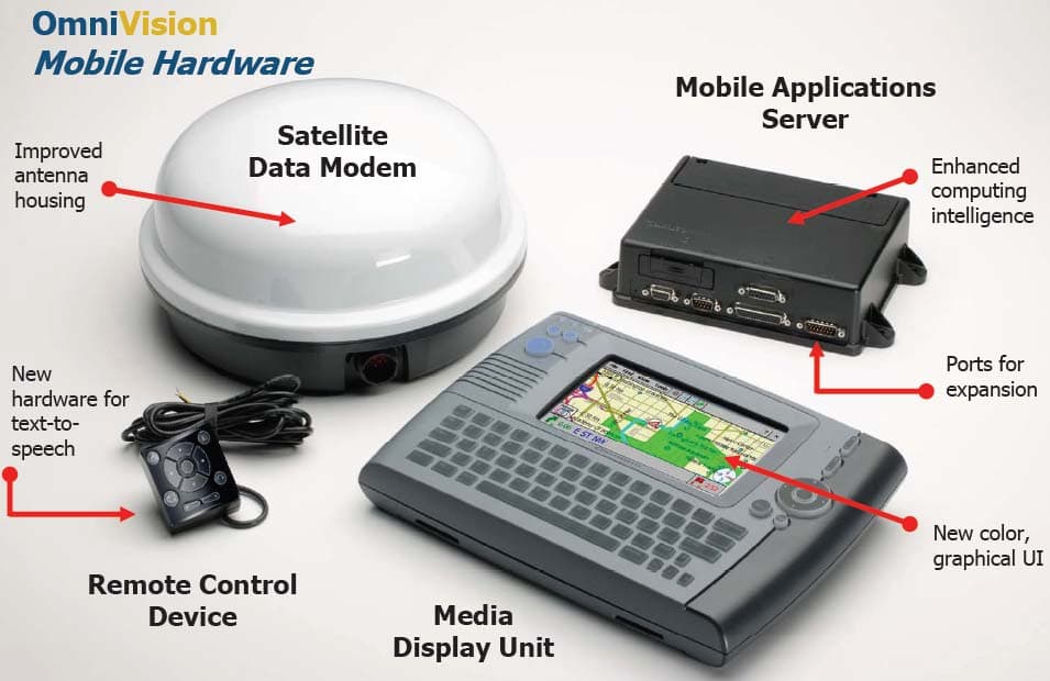
Click to zoom
Application Details
- Equipment Class
- TNB - Licensed Non-Broadcast Station Transmitter
- Date of Grant
- Apr 24, 2006
- Application Purpose
- Original Equipment
- Date of Application
- Apr 24, 2006
- Equipment Note
- Satellite Data Modem
- Frequency Range
- 14000.00000000 - 14500.00000000
- Company
- Qualcomm Technologies, Inc.
- Country
- United States
Documents & Files
Document Text
Text extracted from the exhibit documents filed with the FCC. Open a document above to read the original.
Users Manual
QUALCOMM Incorporated 5775 Morehouse Drive, San Diego, California 92121-1714 US OmniVISION Mobile Computing Platform 80-J4866-1 Rev. A March 2006 OmniVision and Accessory Installation Guide TM TM QUALCOMM Incorporated 5775 Morehouse Drive San Diego, CA 92121-1714 U.S.A. © QUALCOMM Incorporated 2006. All rights reserved. “QUALCOMM, OmniTRACS, TrailerTRACS, SensorTRACS, QTRACS, OmniExpress, MVPc, and Qualcomm Wireless Business Solutions are registered trademarks of QUALCOMM Incorporated.” “OmniVision and TruckMAIL are trademarks of QUALCOMM Incorporated.” All other marks are property of their respective owners. QUALCOMM endeavors to ensure that the information in this document is correct and fairly stated, but QUALCOMM is not liable for any errors or omissions. Published information may not be up to date, and it is important to confirm current status with QUALCOMM. Export of this technology may be controlled by the U.S. Government. Diversion contrary to U.S. law prohibited. 80-J4866-1 Rev. A March 2006 80-J4866-1 Rev. A1/9/06iii ALL INFORMATION SUBJECT TO CHANGE D R A F T DO NOT C O PY Contents Important Safety Information Safety Definitions ................................................................................................ xi Safety Advice ...................................................................................................... xi Chapter 1 How the OmniVision™ System Works OmniVision™ System Overview .......................................................................1-1 Why the OmniVision™ System Makes Companies More Efficient ...................1-2 OmniVision™ System Component Description ................................................1-3 What Is the GPS System? ................................................................................1-4 How the OmniVision™ System Uses GPS .......................................................1-4 What Is the MCP? .............................................................................................1-5 Chapter 2 Component Overview The Equipment You Will Install .........................................................................2-2 How the Components and Cables Interconnect ...............................................2-2 The Satellite Data Modem (SDM) .....................................................................2-4 The Media Display Unit .....................................................................................2-5 The Mobile Application Server (MAS) ...............................................................2-6 The Remote Control Device (RCD) ..................................................................2-7 The Battery Pack ..............................................................................................2-7 Cables ...............................................................................................................2-8 Accessories ....................................................................................................2-12 Chapter 3 Wiring Guidelines Introduction .......................................................................................................3-1 Grounding Guidelines .......................................................................................3-2 Making Electrical Connections ..........................................................................3-2 Wire Stripping .............................................................................................3-2 Butt Splicing ...............................................................................................3-3 Crimping .....................................................................................................3-3 Completing the Wire Connection ................................................................3-6 Ring Terminals ...........................................................................................3-8 Contents iv1/9/0680-J4866-1 Rev. A ALL INFORMATION SUBJECT TO CHANGE D RAF T DO NOT CO PY Chapter 4 Installation Planning Installation Guidelines ...................................................................................... 4-2 Safety ......................................................................................................... 4-2 Security ...................................................................................................... 4-2 Reliability ................................................................................................... 4-3 Accessibility ............................................................................................... 4-3 Typical Installation Sequence .......................................................................... 4-3 Typical Installation Locations ........................................................................... 4-4 Conventional Vehicle Types ....................................................................... 4-5 Cabover Engine (All Makes) Vehicle Types .............................................. 4-8 Tools and Supplies ......................................................................................... 4-11 Acceptable Sealants ................................................................................ 4-12 Installation Planning Worksheet ..................................................................... 4-12 Chapter 5 Satellite Data Modem (SDM) Installation Orienting the SDM on the Mount ...................................................................... 5-2 Installing Mounting Bolts .................................................................................. 5-2 Connecting the SDM Cable .............................................................................. 5-3 General Installation Guidelines ........................................................................ 5-3 Line-of-Sight Requirements ............................................................................. 5-4 Trailer Swing Area .......…
Text truncated - open the document above for the full version.
Cover Letter(s)
QUALCOMM Incorporated 5775 Morehouse Drive (858) 587-1121 San Die go, CA 92121-1714 www.qualcomm.com March 12, 2006 To: Federal Communications Commission Authorization and Evaluation Division Confidentiality Request regarding application for certification of FCC ID: J9COVMCPSDM1 Pursuant to Sections 0.457 and 0.459 of the Commission’s Rules, we hereby request confidential treatment of information accompanying this application as outlined below: Operational Description Schematics Block diagrams Parts lists Internal photos The above materials contain trade secrets and proprietary information not customarily released to the public. The public disclosure of these materials may be harmful to the applicant and provide unjustified benefits to its competitors. The applicant understands that pursuant to Section 0.457 of the Rules, disclosure of this application and all accompanying documentation will not be made before the date of the Grant for this application. Sincerely, Fang Han Senior Staff Regulatory Engineer QUALCOMM, INC.
External Photos
Appendix K. Rule 2.1033(c)(12) – External Photos Figure K–1. SDM in MCP System Configuration 80-JXXXX-X Rev. A QUALCOMM Proprietary K-1 Rule 2.1033(c)(12) – External Photos SDM FCC Certification Report Figure K–2. SDM outlook K-2 QUALCOMM Proprietary 80-JXXXX-X Rev. A
ID Label/Location Info
Appendix J. Rule 2.1033(c)(11)/2.925 – Label/Location Figure J–1. Product label on side of the housing 80-JXXXX-X Rev. A QUALCOMM Proprietary J-1 Rule 2.1033(c)(11)/2.925 – Label/Location SDM FCC Certification Report Figure J–2. FCC ID label on bottom of the housing J-2 QUALCOMM Proprietary 80-JXXXX-X Rev. A SDM FCC Certification Report Rule 2.1033(c)(11)/2.925 – Label/Location Figure J–3. Zoom-in FCC ID 80-JXXXX-X Rev. A QUALCOMM Proprietary J-3
Parts List/Tune Up Info
SDM FCC Certification Report Operational Description Chan asgn is the channel assignment given to the terminal for the packet transmission NumChan is the number of return link frequency channels C.4 Tune-up procedure Refer to session C.1 through C.3. C.5 Frequency stability device A voltage controlled, temperature compensated, crystal oscillator (VCTCXO) is employed as a frequency reference for all of the transceiver local oscillators. This crystal oscillator is specified to remain within +/- 8 ppm over temperature and voltage variations. The lock status indicator of all synthesizers is monitored by the microprocessor and an out of lock condition will inhibit transmission. C.6 Spurious suppression C.6.1 Suppression device Reference Designator Part Name Function Rx amp filters Image reject BPF Provides protection against receive spurious emissions and receiver local oscillator leakage Tx amp filters TX BPF Provides protection against transmitter spurious emissions and transmit local oscillator leakage Rx amp mixer filters Rx PA filter Provides protection against receiver local oscillator leakage Tx amp mixer filters TX PA filter Provides suppression of spurious energy and transmitter harmonics Rx IF filter RX_IF BPF Provides other than RX_IF emission Tx IF filter TX_IF BPF Provides other than TX_IF emission Sheet shields SHSH1, 2, 5, 6, 8, 10, 11, 13, 14, 15, 21 Provides on-board shielding of critical circuits that might generate spurious emission LC filters numerous Provides suppression of emission from power switch and digital circuit C.6.2 Frequency hopping correction factor The RF spurious emissions being radiated in carrier-on state by the SDM are harmonically related to the local oscillators (and their mixed products) in the digital 80-JXXXX-X Rev. A QUALCOMM Proprietary C-9 Operational Description SDM FCC Certification Report and RF CCA. The local oscillators are tuned to different frequencies every 20 ms (half of the hopping period) to switch between the receive frequency and the hopped transmit frequency and vice versa. Due to this constant re-tuning of the local oscillators, the frequencies of the spurious emissions are constantly changing, or hopping, every 20 ms as well. This hopping of the spurious emissions allows us to spread their power over the entire hopping bandwidth (36 MHz for domestic system) of the transmitted signal. If the measurement bandwidth is 100 kHz, there is a spreading factor of: dB 6.25 100 000,36 log10= ⎟ ⎠ ⎞ ⎜ ⎝ ⎛ The hopping of the spurious emissions can also be seen in factory mode by setting up the spectrum analyzer to measure a spurious emission in any given 100 kHz band, and simply changing the transmit frequency on the display unit screen. The spurious response of the SDM will change depending on the transmit frequency in hopping. The above spread factor of 25.6 dB can be taken into account in the measurement of carrier-on spurious emissions. C-10 QUALCOMM Proprietary 80-JXXXX-X Rev. A
Test Report
Note: The test report is specially limited to the use of the above client company and this particular sample only. It may not be duplicated without prior written consent of Bay Area Compliance Laboratory Corporation. This report must not be used by the client to claim product certification, approval, or endorsement by NVLAP, NIST or any agency of the U.S. Government. FCC PART 25 TYPE SUPPLEMENT EMI MEASUREMENT AND TEST REPORT For QUALCOMM Incorporated FCC ID: J9COVMCPSDM1 This Report Concerns: Original Report Equipment Type: Satellite Earth Station Equipment Test Engineer: Snell Leong Report No.: N/A Report Date: 2006-04-07 Reviewed By: Daniel Deng Prepared By: Bay Area Compliance Laboratory Corporation (BACL) 230 Commercial Street Sunnyvale, CA 94085 Tel: (408) 732-9162 Fax: (408) 732 9164 Globalstar USA, LLC FCC ID: TSEFAU200RA Report # Supplement report Page 2 of 42 FCC Part 25 Test Report TABLE OF CONTENTS GENERAL INFORMATION.......................................................................................................................................3 PRODUCT DESCRIPTION FOR EQUIPMENT UNDER TEST (EUT) ....................................................................................3 OBJECTIVE...................................................................................................................................................................3 RELATED SUBMITTAL(S)/GRANT(S).............................................................................................................................3 TEST METHODOLOGY..................................................................................................................................................3 TEST FACILITY.............................................................................................................................................................3 SYSTEM TEST CONFIGURATION ..........................................................................................................................4 JUSTIFICATION.............................................................................................................................................................4 SPECIAL ACCESSORIES.................................................................................................................................................4 EQUIPMENT MODIFICATIONS.......................................................................................................................................4 LOCAL SUPPORT EQUIPMENT LIST AND DETAILS........................................................................................................4 POWER SUPPLY INFORMATION.....................................................................................................................................4 EXTERNAL I/O CABLING LIST AND DETAILS................................................................................................................4 SUMMARY OF TEST RESULTS ...............................................................................................................................5 § 2.1053 & §25.202 (F) – FIELD STRENGTH OF SPURIOUS RADIATION ........................................................6 STANDARD APPLICABLE..............................................................................................................................................6 MEASUREMENT PROCEDURE........................................................................................................................................6 EQUIPMENT LISTS........................................................................................................................................................6 MEASUREMENT RESULT..............................................................................................................................................7 §25.202(F) – EMISSION MASK ..................................................................................................................................8 STANDARD APPLICABLE..............................................................................................................................................8 MEASUREMENT PROCEDURE........................................................................................................................................8 EQUIPMENT LISTS........................................................................................................................................................8 MEASUREMENT RESULT..............................................................................................................................................8 EXHIBIT B - TEST SETUP PHOTOGRAPHS ......................................................................................................10 RADIATED SETUP – VIEW 1........................................................................................................................................10 RADIATED SETUP – VIEW 2........................................................................................................................................11 Globalstar USA, LLC FCC ID: TSEFAU200RA Report # Supplement report Page 3 of 42 FCC Part 25 Test Report GENERAL INFORMATION Product Description for Equipment Under Test (EUT) Please see Main Test report. Objective This test report is used intended as supplement to main report. Related Submittal(s)/Grant(s) No Related Submittals. Test Methodology All measurements contained in this report were conducted with TIA 603-C. All radiated and conducted emissions measurement was performed at Bay Area Compliance Laboratory, Corp. Test Facility The Open Area Test site used by BACL to collect radiated and conducted emission measurement data is located in the back parking lot of the building at 230 Commercial Street, Sunnyvale, California, USA with registration number: 90464. Test site at BACL has been fully descr…
Text truncated - open the document above for the full version.
Test Report
Appendix D. Test Report of Rule 2.1046 – 2.1055 D.1 EUT Overview Job Number: 06014 Doc Path: V:\EMC Result.Data\2006\ 06014 Project Title: QC SDM FCC Pre-Cert Completion date: March 1, 2006 EUT: SDM stand alone with J8700 board P/N: 10-J8728-1 on J8700-1 Rev A S/N: Unit: 100000546S Temperature: 24 o C Relative Humidity: 57% Barometric Pressure: 754mm Tested by Suzy Galati, Fang Han D.2 List of Test Equipment Table D–1. Test equipment for radiated emission No. Manufacturer/ Type No. Part/Model No.Serial No. Cal Date & Cal Due Date 1 R&S EMI Test Receiver 9 kHz to 2.5 GHz ESPC DE14759/845296/0 20 18 Oct 05 18 Oct 06 2 HP Pre Amp. 8447D OPT 010 2944A09692 28 Oct 05 28 Oct 06 4 Chase X-Wing Antenna 20 to 2000 MHz CBL6140A 1151 21 Apr 05 21 Apr 06 7 Gore Coax Cables N-type #10, 12,14 30 June 05 30 June 06 8 Agilent Spectrum Analyzer 3Hz to 25 GHz E4440A MY44022417 2 Aug 05 2 Aug 06 9 CSZ Dimension Temperature Chamber ZP-8 R-404A 20 July 05 20 July 06 D.3 Rule 2.1051/25.204 – Conducted RF Power Output D.3.1 Test procedure Definition - The output power rating of the transmitter is the power available at the output terminal of the transmitter when the terminal is connected to the normal load. Minimum Standard - The nominated transmitter output power is 30 dBm and shall be maintained within range of 28.5 dBm to 32.5 dBm at extreme temperature. Method of Measurement - The conducted RF power output is measured per Part 2.1046(a). The transmitter output carrier power with MSK modulation mode or CW mode can measured using a spectrum analyzer. The measurement setup diagram is shown in Figure D-1. Spectrum Analyzer or PSA 10 VDC PC with DVT software RF output SDM Power and debug cable Figure D–1. Measurement setup for conducted RF power Using the above setup, the conducted RF power output, emission mask and spurious emission can be measured simultaneously by the following steps: 1. Conducted Tx RF power output and emission mask a) Connect the waveguide to SDM antenna port and then connect the waveguide to PSA via a low loss co-ax cable. b) At initial Tx mode setup, select the CW mode and low channel selection. Note: once the MSK is enabled, it cannot be turned back to CW by the DVT software unless the EUT is rebooted. c) At V-pol, Set CENTER FREQUENCY of PSA to the current Tx frequency (at low, mid or high channel). Set the frequency span to 5 MHz and RBW to 4 kHz. d) Under trace 1, set necessary attenuation and reference level to avoid overloading. Then, align the beam, maximize the carrier emission and mark the peak with marker 1. Then PEAK HOLD for seconds and turn to VIEW to stabilize trace 1 as V-pol CW emission. e) While keep Trace 1 on, activate trace 2. Then enable MSK at the DVT setup. f) PEAK HOLD trace 2 for seconds and turn it to VIEW to stabilize trace 2. Mark the peak of the first side lobe with Marker 2. g) Turn full display and take a plot (Power and emission mask plot). h) Enable the MARKER TABLE and take a full plot again. (Power and emission mask plot with marker data). 2. Spurious emission a) Blank trace 2 above and clear trace 1. b) Change the RBW to 100 kHz, and take full plot of emission profile for 1-10 GHz, 10-14 GHz, 14-14.5 GHz, and 14.5 to 18 GHz. Always put the marker on the peak of the emission profiles. c) Repeat step 1b) through 1h) above for mid channel. d) Repeat step 1b) through 2c) above for high channel. D.3.2 Measurement result The antenna port of the equipment is terminated to a 50 ohms resistive load of the PSA. The nominal power from the antenna port is 1 W (30 dBm). The carrier power was measured at CW state. The PAS setup is shown in Table D–2. Table D–2. Spectrum setup for conducted emission Frequency (GHz) Internal att (dB) Ref level (dB) Level Offset (dB) RBW (kHz) Carrier type External att (dB) 1-10 10 10 10 100 MSK 10 10-14 26 26 10 100 MSK 10 14-14.5 30 30 10 100 MSK 10 14.5-18 26 26 10 100 MSK 10 Table D–3. Conducted RF power output (W) Channel in Ku-band Carrier frequency (MHz) Specs (dBm) Max level (dBm) PWR density (dBm/4kH) FCC limit (dBm/4kH) Low 14005 (LO/IF=12920/1085) 30±2 29.73 4.13 70 Mid 14250 (LO/IF=13160/1095) 30±2 30.02 4.43 70 High 14495 (LO/IF=13400/1095) 30±2 28.55 2.96 70 Table D-3 and Figure D-2 to Figure D-4 shows the measured data and waveform. Figure D–2. Conducted RF power at antenna flange, low band Figure D–3. Conducted RF power from antenna flange, mid band Figure D–4. Conducted RF power from antenna flange, high band D.4 Rule 2.1046/25.204 – Radiated RF Power Output D.4.1 Test procedure Definition - The radiated power is the EIRP from the transmitter antenna. Minimum Standard - The transmitter output power shall be maintained within 50 dBm which is below the power limit of 40 dBW by FCC rule 25.204. Method of Measurement - The EIRP with CW and MSK modulation can be measured in an anechoic chamber. The measurement setup diagram is shown in Figure D-5. Radiation receiving system 10 VDC and control port SDM Receive antenna Figure D–5. Measurement setup for radiated emission and EIRP The radiated RF power output, emission mask and spurious emission can be measured simultaneously by the following steps: 1. Radiated Tx RF power output and emission mask a) At initial Tx mode setup, select the CW mode and low channel selection. Note: once the MSK is enabled, it cannot be turned back to CW by the DVT software unless the EUT is rebooted. b) At V-pol, Set CENTER FREQUENCY of PSA to the current Tx frequency (at low, mid or high channel). Set the frequency span to 5 MHz and RBW to 4 kHz. c) Under trace-1, set necessary attenuation and reference level to avoid overloading. Then, align the beam, maximize the carrier emission and mark the peak with marker 1. Then PEAK HOLD for seconds and turn to VIEW to stabilize trace 1 as V-pol CW emission. d) While keep Trace-1 on, activate trace-2. Then enable MSK at the DVT setup. e) PEAK HOLD trace-2 for seconds and turn it to VIEW to stabilize trace-2. Mark the peak of the first side lobe with Marker …
Text truncated - open the document above for the full version.
Test Setup Photos
Appendix E. Test Setup Photos E.1 Conducted RF power and spurious emissions 80-JXXXX-X Rev. A QUALCOMM Proprietary E-1 Test Setup Photos SDM FCC Certification Report E.2 Radiated emissions Figure E–1. SDM in radiated measurement E-2 QUALCOMM Proprietary 80-JXXXX-X Rev. A SDM FCC Certification Report Test Setup Photos Figure E–2. SDM radiated test setup E.3 Occupied bandwidth As shown in Figure E–1. 80-JXXXX-X Rev. A QUALCOMM Proprietary E-3 Test Setup Photos SDM FCC Certification Report E.4 Frequency stability E-4 QUALCOMM Proprietary 80-JXXXX-X Rev. A SDM FCC Certification Report Test Setup Photos 80-JXXXX-X Rev. A QUALCOMM Proprietary E-5
Contact Information
Applicant
Paul Guckian(Vice President, Regulatory Engineering)
Test Firm
Bay Area Compliance LaboratoryJohn Chan
Technical Specifications
| # | Rule Parts | Frequency Range | Power Output | Emission | Tolerance |
|---|---|---|---|---|---|
| 2 | 25 | 14.00 GHz - 14.50 GHz | 1.26 W | 36M0F1D | 10 ppm |
Other Applications from Qualcomm Technologies, Inc.
J9C-M2X75
Aug 13, 2024Module
Equipment Class
CBE - Citizens Band End User DevicesJ9C-M2X72
Aug 13, 2024Module
Equipment Class
PCB - PCS Licensed Transmitter
J9C-QCNCM825
Aug 26, 2023Qualcomm WiFi 7/BT Combo module
Equipment Class
6CD - 15E 6 GHz Low Power Dual Client
J9C-QCNCM865
Apr 04, 2023Qualcomm WiFi 7/BT Combo module
Equipment Class
NII - Unlicensed National Information Infrastructure TX
J9CQCARD7280N
Nov 07, 2022QCARD7280
Equipment Class
DTS - Digital Transmission System