J9CRFFE1900Part 24 Base Station
Qualcomm Technologies, Inc.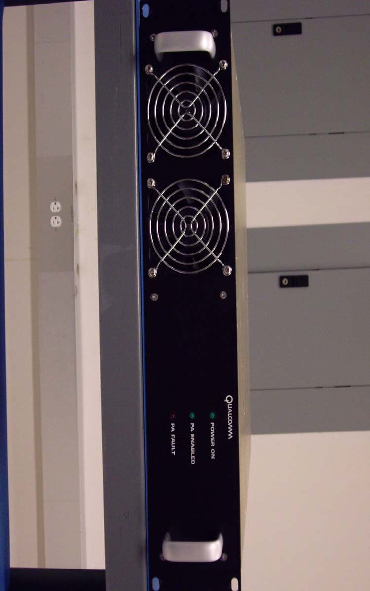
Click to zoom
Application Details
- Equipment Class
- PCB - PCS Licensed Transmitter
- Date of Grant
- Sep 12, 2007
- Application Purpose
- Original Equipment
- Date of Application
- Sep 12, 2007
- Equipment Note
- Part 24 Base Station
- Frequency Range
- 1931.25000000 - 1988.75000000
- Company
- Qualcomm Technologies, Inc.
- Country
- United States
Documents & Files
Document Text
Text extracted from the exhibit documents filed with the FCC. Open a document above to read the original.
Users Manual
QUALCOMM Deployable Base Station–Broadband Hardware Setup Guide 80-D9001-1 Rev. A MAY CONTAIN U.S. EXPORT CONTROLLED INFORMATION 1 2 3 4 5 6 7 8 9 10 11 12 13 14 15 16 17 18 19 20 21 22 23 24 CC/IC Notice FCC notice This device complies with part 15 of the FCC rules. Operation is subject to the following two conditions: (1) this device may not cause harmful interference, and (2) this device must accept any interference received, including interference that may cause undesired operation. QUALCOMM reserves the right to make changes in technical and product specifications without prior notice. This technical data may be subject to U.S. export, re-export or transfer (“export”) laws. Diversion contrary to U.S. law is prohibited. QUALCOMM and QSec are registered trademarks and registered service marks of QUALCOMM Incorporated and QDBS is a trademark of QUALCOMM Incorporated. All other trademarks and registered trademarks are the property of their respective owners. Sun, Sun Microsystems, the Sun logo and Solaris are trademarks or registered trademarks of Sun Microsysytems, Inc. in the U.S. and other countries. QUALCOMM Proprietary: All data and information contained in or disclosed by this document are confidential and proprietary information of QUALCOMM Incorporated, and all rights therein are expressly reserved. By accepting this material, the recipient agrees that this material and the information contained therein are held in confidence and in trust and will not be used, copied, reproduced in whole or in part, nor its contents revealed in any manner to other without the express written permission of QUALCOMM Incorporated. © 2007 QUALCOMM Incorporated All rights reserved QUALCOMM Incorporated 5775 Morehouse Drive San Diego CA 92121-1714 www.qualcomm.com 80-D9001-1 Rev. A - v - QUALCOMM Confidential and Proprietary MAY CONTAIN U.S. EXPORT CONTROLLED INFORMATION 80-D9001-1 Rev. A 1 2 3 The products and equipment described in this document are manufactured under one or more of the following U.S. Patents: D424,052 D361,065 D397,110 D413,117 D427,143 D386,186 D429,210 D429,212 D426,219 D422,262 412,483 D416,555 D356,560 D409,561 D424,573 D407,701 D375,740 D376,804 D411,823 D393,856 413,857 D413,860 D410,893 D375,937 D421,981 4,901,307 5,056,109 5,099,204 5,101,501 5,103,459 5,107,225 5,109,390 5,193,094 5,228,054 5,257,283 5,265,119 5,267,261 5,267,262 5,280,472 5,283,536 5,289,527 5,307,405 5,309,474 5,337,338 5,339,046 5,341,456 5,383,219 5,392,287 5,396,516 5,408,697 5,414,728 5,414,796 5,416,797 5,426,392 5,437,055 5,442,322 5,442,627 5,452,473 5,461,639 5,469,115 5,469,471 5,471,497 5,475,870 5,479,475 5,483,696 5,485,486 5,487,175 5,490,165 5,497,395 5,499,280 5,504,773 5,506,865 5,509,015 5,509,035 5,511,067 5,511,073 5,513,176 5,515,177 5,517,323 5,519,761 5,528,593 5,530,928 5,533,011 5,535,239 5,539,531 5,544,196 5,544,223 5,546,459 5,548,812 5,559,865 5,559,881 5,561,618 5,564,083 5,566,000 5,566,206 5,566,357 5,568,483 5,574,773 5,574,987 5,576,662 5,577,022 5,577,265 5,588,043 5,589,756 5,590,069 5,590,406 5,590,408 5,592,548 5,594,718 5,596,570 5,600,754 5,602,833 5,602,834 5,603,096 5,604,459 5,604,730 5,608,722 5,614,806 5,617,060 5,621,752 5,621,784 5,621,853 5,625,876 5,627,857 5,629,955 5,629,975 5,638,412 5,640,414 5,642,398 5,644,591 5,644,596 5,646,991 5,652,814 5,654,979 5,655,220 5,657,420 5,659,569 5,663,807 5,666,122 5,673,259 5,675,581 5,675,644 5,680,395 5,687,229 5,689,557 5,691,974 5,692,006 5,696,468 5,697,055 5,703,902 5,704,001 5,708,448 5,710,521 5,710,758 5,710,768 5,710,784 5,715,236 5,715,526 5,722,044 5,722,053 5,722,061 5,722,063 5,724,385 5,727,123 5,729,540 5,732,134 5,732,341 5,734,716 5,737,687 5,737,708 5,742,734 5,748,104 5,751,725 5,751,761 5,751,901 5,754,533 5,754,542 5,754,733 5,757,767 5,757,858 5,758,266 5,761,204 5,764,687 5,774,496 5,777,990 5,778,024 5,778,338 5,781,543 5,781,856 5,781,867 5,784,406 5,784,532 5,790,589 5,790,632 5,793,338 5,799,005 5,799,254 5,802,105 5,805,648 5,805,843 5,812,036 5,812,094 5,812,097 5,812,538 5,812,607 5,812,651 5,812,938 5,818,871 5,822,318 5,825,253 5,828,348 5,828,661 5,835,065 5,835,847 5,839,052 5,841,806 5,842,124 5,844,784 5,844,885 5,844,899 5,844,985 5,848,063 5,848,099 5,850,612 5,852,421 5,854,565 5,854,786 5,857,147 5,859,612 5,859,838 5,859,840 5,861,844 5,862,471 5,862,474 5,864,760 5,864,763 5,867,527 5,867,763 5,870,427 5,870,431 5,870,631 5,870,674 5,872,481 5,872,774 5,872,775 5,872,823 5,877,942 5,878,036 5,881,053 5,881,368 5,884,157 5,884,193 5,884,196 5,892,178 5,892,758 5,892,774 5,892,816 5,892,916 5,893,035 5,898,920 5,903,554 5,903,862 5,907,167 5,909,434 5,910,752 5,911,128 5,912,882 5,914,950 5,915,235 5,917,708 5,917,811 5,917,812 5,917,837 5,920,284 5,920,834 5,923,650 5,923,705 5,926,143 5,926,470 5,926,500 5,926,786 5,926,786 5,930,230 5,930,692 5,933,462 5,933,781 5,933,787 5,936,582 5,937,019 5,940,383 5,940,761 5,942,929 5,943,361 5,943,606 5,943,615 5,946,614 5,946,618 5,949,814 5,953,320 5,953,322 5,953,648 5,953,674 5,956,651 5,956,683 5,959,583 5,960,361 5,960,362 5,963,867 5,966,652 5,970,413 5,974,041 5,974,356 5,978,679 5,982,315 5,982,333 5,982,760 5,983,099 5,983,114 5,983,119 5,984,697 5,986,620 5,987,076 5,987,122 5,987,326 5,988,583 5,990,847 5,991,284 5,991,345 5,995,821 5,997,314 5,999,816 5,999,828 6,002,933 6,005,506 6,005,855 6,006,108 6,007,378 6,008,762 6,009,307 6,011,796 6,011,978 6,016,568 6,021,122 6,023,717 6,026,292 6,028,884 6,028,984 6,032,039 6,035,209 6,037,750 6,038,037 6,044,074 6,044,103 6,049,305 6,055,428 6,058,338 6,060,949 6,061,336 6,064,678 6,067,458 6,069,525 6,069,526 6,069,880 6,069,888 6,070,085 6,070,835 6,073,007 6,073,013 6,075,847 6,075,859 6,075,974 6,078,284 6,081,229 6,081,724 6,084,870 6,085,085 6,085,349 6,091,299 6,094,465 6,097,339 6,097,972 6,101,168 6,101,173 6,101,179 6,101,397 6,107,878 6,107,959 6,107,969 6,107,977 6,108,364 6,108,372 6,108,536 6,108,591 6,111,865 6,114,996 6,115,142 6,115,607 6,118,250 6,118,765 6,1…
Text truncated - open the document above for the full version.
Users Manual
Unpacking and Inspecting QDBS–Broadband Hardware Quantity Description Equipment 1 Ethernet Cable (Radio-Network) 2 Attenuators 2 Whip Antennas 1 Optional for use with QDBS-Cellular overlay. OA&M computer (with Power Adapter) 2 Optional for use with QDBS-Cellular overlay. Ethernet cables for the OA&M computer Software Disks (CD-ROM and DVD) Documentation - 23 - QUALCOMM Confidential and Proprietary MAY CONTAIN U.S. EXPORT CONTROLLED INFORMATION 80-D9001-1 Rev. A QDBS–Broadband Hardware Section 4 - 24 - QUALCOMM Confidential and Proprietary MAY CONTAIN U.S. EXPORT CONTROLLED INFORMATION 80-D9001-1 Rev. A 1 2 3 4 This section provides specific descriptions of the QDBS–Broadband hardware components. 4.1. Radio Case components Figure 5 identifies the major components of the Radio Case. Each component is described in the following subsections. Note: Some Radio components are mounted in the rear of the transit case. 5 6 7 Figure 5: Radio Case components (front view) QDBS–Broadband Hardware - 25 - QUALCOMM Confidential and Proprietary MAY CONTAIN U.S. EXPORT CONTROLLED INFORMATION 80-D9001-1 Rev. A 1 2 4.2. Operations, Administration, and Maintenance Computer CAUTION: Do not install additional software onto the OA&M computer. Additional software may cause OA&M operations to malfunction. 3 4 5 6 7 8 9 10 11 12 The Operations, Administration, and Maintenance (OA&M) computer is installed with a CentOS Linux operating system (OS), and is used to perform system configuration, operation, and maintenance through the user interface (UI) and/or command line interface (CLI). The OA&M computer also controls the power (on/off) to the individual AC line receptacles of the RN and RNC Power Distribution Units (PDUs). QDBS–Broadband applications running on the OA&M Computer can operate with the laptop in the open or closed position. When the computer is closed, the Element Management System continues to function by receiving updates of component status, log events, etc. 13 14 15 Figure 6: OA&M Computer The OA&M Computer is stored in a cover of the Network Case. QDBS–Broadband Hardware - 26 - QUALCOMM Confidential and Proprietary MAY CONTAIN U.S. EXPORT CONTROLLED INFORMATION 80-D9001-1 Rev. A 1 2 3 4 5 6 7 8 9 4.2.1. Radio Node (RN) The RN provides radio resources and maintains radio links with the Access Terminal (AT). The RN implements the Physical and Media Access Control (MAC) layers of the EV-DO protocol stack. The RN is analogous to the BTS in the QDBS-Cellular. 4.2.2. Power Distribution Unit (PDU) The PDU is a power controller that provides AC power, EMI/RFI filtering, and spike/surge protection to the components in the transit case. While the PDU has a master power switch and eight momentary touch-switches that control the eight individual AC line receptacles, these switches should not be turned on or off manually, as they are controlled by the OA&M computer. CAUTION: Turning off the components manually using the PDU’s individual (numbered) switches, may cause irreparable damage to the components. 10 11 12 4.2.3. Radio Frequency Front End (RFFE) WARNING: Do not begin radiating an RF signal unless the appropriately loaded antennas are connected to the RF terminals (TxRx0 and Rx1 of the RAN Connector Interface Panel). Exposure to high levels of RF energy could result, causing bodily injury. 13 14 15 16 17 18 19 20 21 22 23 24 25 26 27 28 29 The RFFE is a single sector, 20 W power amplifier that boosts the signal from the RN sector to the Tx/Rx0 and Rx1 antennas, resulting in greater coverage area. When the RN is used with the RFFE, the radio is referred to as macro-cell. Each RN can support up to three sectors (each sector requiring its own RFFE). The basic QDBS–Broadband, however, includes only one RFFE and can therefore accommodate only one macro-sector. Additional RFFEs may be added to the QDBS–Broadband (up to three per RN) to increase the number of macro-sectors. The RFFE contains an internal Ethernet controller with Digital and Analog signals. The OAM laptop controls the RFFE output power level, calibration, output protection and status monitoring via the Ethernet controller. The RN RF output is connected to the RFFE input through Sub- Miniature version A (SMA) connectors on the back of the RFFE and on the front the RN. The RFFE output is connected to the Tx/Rx0 and Rx1 antennas using two N-type connectors (one for transmitting and one for receiving) on the Radio Case CIP. The front of the RFFE is shown in Figure 5. The rear of the RFFE is denoted with in Figure 7. QDBS–Broadband Hardware - 27 - QUALCOMM Confidential and Proprietary MAY CONTAIN U.S. EXPORT CONTROLLED INFORMATION 80-D9001-1 Rev. A 1 2 3 4 5 6 7 Figure 7: Radio Case (rear panel view) 4.2.4. Connector Interface Panel The Connector Interface Panel (CIP) is a cable pass-through panel designed to make connecting and disconnecting the various serial and Ethernet connections in the transit cases easier. The CIP is located in the rear of the transit case and is denoted with in Figure 7, while CIP detail is shown in Figure 8. QDBS–Broadband Hardware - 28 - QUALCOMM Confidential and Proprietary MAY CONTAIN U.S. EXPORT CONTROLLED INFORMATION 80-D9001-1 Rev. A 1 2 3 4 5 6 7 8 9 Figure 8: Detail of the Radio Case CIP 4.2.5. Ethernet switch The Ethernet switch denoted with in Figure 7 is used for Ethernet connectivity and Local Area Network Internet Protocol (LAN IP) communications. The Ethernet switch has 16 10/100 Mb/s auto-speed Ethernet ports and built-in link and activity lights. Access to the switch is from the rear of the Radio Case. All major components of the Radio Case (RN, RNC, and RFFE) connect to the Ethernet switch and communicate with each other using IP. QDBS–Broadband Hardware - 29 - QUALCOMM Confidential and Proprietary MAY CONTAIN U.S. EXPORT CONTROLLED INFORMATION 80-D9001-1 Rev. A 1 4.2.6. RF antennas WARNING: When operating the QDBS–Broadband in pico-cell mode, install a 30 dB attenuator between the transmit port of the RAN C…
Text truncated - open the document above for the full version.
Cover Letter(s)
Applicant: Qualcomm Inc. FCC ID: J9CQRFFE1900 8/12/07 Nemko Canada Inc 303 River Road Ottawa, Ontario, Canada K1V 1H2 Attn: Director of Certification FCC ID: J9CRFFE1900 Authority to Act as Agent On our behalf, I appoint Nemko USA Inc., 11696 Sorrento Valley Rd, San Diego, CA, USA to act as our agent in the preparation of this application for equipment certification. I certify that submitted documents properly describe the device or system for which equipment certification is sought. I also certify that each unit manufactured, imported or marketed, as defined in Industry Canada’s regulations will have affixed to it a label identical to that submitted for approval with this application. For instances where our authorized agent signs the application for certification on our behalf, I acknowledge that all responsibility for complying with the terms and conditions for certification, as specified by Nemko Canada Inc, still resides with Qualcomm INC., 5775 Morehouse Drive, San Diego, CA. 92121. Dated this 12 Day of August 20 07 Agency agreement expiration date: 12 Months Qualcomm Inc. Robert J Scodellaro EMC Engineer, Senior Staff Manager
Cover Letter(s)
Applicant: Qualcomm Inc. FCC ID: J9CQRFFE1900 Request of Confidentiality Federal Communications Commission Authorization and Evaluation Division Re: Request of Confidentiality FCC ID: J9CRFFE1900 Pursuant to Sections 0.457 and 0.459 of the Commission’s Rules, the Applicant hereby requests confidential treatment of information accompanying this Application as outlined below: All schematics All parts lists Block Diagram Operation Description Internal Photos The above materials contain trade secrets and proprietary information not customarily released to the public. The public disclosure of these matters might be harmful to the Applicant and provide unjustified benefits to its competitors. The device is not accessible to general public as it is installed in areas the public has no access to therefore we ask that Internal Photos be held confidential. The Applicant understands that pursuant to Rule 0.457, disclosure of this Application and all accompanying documentation will not be made before the date of the Grant for this Application. Qualcomm Inc. Robert J Scodellaro EMC Engineer, Senior Staff Manager
External Photos
RFFE External Pictures RFFE Front Panel RFFE Top and Left Sides RFFE Right Side RFFE Rear Panel RFFW Bottom Panel
ID Label/Location Info
Released Released
ID Label/Location Info
Released Released Woodard, James R. (jwoodard) 07/25/07 Released Released Woodard, James R. (jwoodard) 07/25/07 Released Released Woodard, James R. (jwoodard) 07/25/07
Parts List/Tune Up Info
Applicant: Qualcomm Inc. FCC ID: J9CQRFFE1900 Device Description The Qualcomm Radio Frequency Front End (RFFE) is a 1900 MHz, single sector power amplifier, transmitting a macro cell output signal up to 20 watts. The RFFE is 2U in height and mounts into a 19 inch rack. The RFFE is part of a CDMA deployable base station. Tune-up Procedure There are no field tunable components in the RFFE amplifier. Qualcomm Inc. Robert J Scodellaro EMC Engineer, Senior Staff Manager
RF Exposure Info
Applicant: Qualcomm Inc. FCC ID: J9CQRFFE1900 RF Exposure Evaluation (FCC 2.1091, 24.52) The RFFE is a RF power amplifier that is integrated into a larger system to form a portable PCS base station. To calculate the safe distance where the Maximum Permissible Exposure (MPE) satisfies the FCC 1.1310 limit for General Population/Uncontrolled Exposure, the formula is used: D ≥ )4/(SEIRPπ D is the distance from the antenna in meters EIRP is the effective radiating power with respect to an isotropic radiator S is the power density in W/m 2 The RFFE has a maximum conducted power of 20W and the antenna used with the system has a gain of 12 dBi. This results in an EIRP of 316.2W. The MPE limit at 1960 MHz is 1.0 mW/cm 2 (or 10 W/m 2 ) for the General Population/Uncontrolled Exposure. When these values are entered in the above formula, the distance D to satisfy the MPE standard is 1.59m. A RF Safety section is included in the user’s manual that states the minimum separation distance of 1.59m between the antenna and any personnel. Qualcomm Inc. Robert J Scodellaro EMC Engineer, Senior Staff Manager
Test Report
Nemko USA, Inc. 11696 Sorrento Valley Rd., Suite F San Diego, CA 92121-1024 Phone (858) 755-5525 Fax (858) 452-1810 Certification Test Report Test Report: 2007 075409 RFFE FCC Project number: 5409-1 Applicant: Qualcomm Incorporated 5775 Morehouse Drive San Diego, CA 92121 Equipment Under Test (EUT): RF Amplifier Model: RFFE1900 Antenna Model: Mobile Mark Antenna (CVS-900/1900) with attenuator FCC ID: FCC ID # J9CRFFE1900 Industry Canada: 3572A-M200 In Accordance With: FCC Part 24, Subpart E Tested By: Nemko USA Inc. 11696 Sorrento Valley Road, Suite F San Diego, CA 92121 Authorized By: FR. Fleury FR. Fleury, Manager Date: A UGUST 1, 2007 Total Number of Pages: 25 Nemko USA, Inc. 11696 Sorrento Valley Road, Suite F, San Diego, CA 92121 Phone (858) 755-5525 - Fax (858) 452-1810 Report Number: 2007 075409 RFFE FCC FCC ID: FCC ID # J9CRFFE1900 Specification: FCC Part 22 Subpart H, Part 24 Subpart E Page 2 of 16 Report Summary All measurements are traceable to national standards. These tests were conducted on a sample of the equipment for the purpose of demonstrating compliance with FCC Part 24, Subpart E. The assessment summary is as follows: Apparatus Assessed: RFFE1900 RF Amplifier Specification: FCC Part 24, Subpart E Compliance Status: Complies Exclusions: None Non-compliances: None Nemko USA, Inc. 11696 Sorrento Valley Road, Suite F, San Diego, CA 92121 Phone (858) 755-5525 - Fax (858) 452-1810 Report Number: 2007 075409 RFFE FCC FCC ID: FCC ID # J9CRFFE1900 Specification: FCC Part 22 Subpart H, Part 24 Subpart E Page 3 of 16 Report Release History: REVISION DATE COMMENTS - August 1, 2007 Prepared By: Alan Laudani - August 1, 2007 Initial Release: FR Fleury Note that the results contained in this report relate only to the items tested and were obtained in the period between the date of initial receipt of samples and the date of issue of the report. This test report has been completed in accordance with the requirements of ISO/IEC 17025. Nemko USA Inc. authorizes the applicant to reproduce this report provided it is reproduced in its entirety and for use by the company’s employees only. Any use which a third party makes of this report, or any reliance on or decisions to be made based on it, are the responsibility of such third parties. Nemko USA Inc. accepts no responsibility for damages, if any, suffered by any third party as a result of decisions made or actions based on this report. Nemko USA, Inc. 11696 Sorrento Valley Road, Suite F, San Diego, CA 92121 Phone (858) 755-5525 - Fax (858) 452-1810 Report Number: 2007 075409 RFFE FCC FCC ID: FCC ID # J9CRFFE1900 Specification: FCC Part 22 Subpart H, Part 24 Subpart E Page 4 of 16 TABLE OF CONTENTS Report Summary......................................................................................................................................... 2 Section 1: Equipment Under Test.............................................................................................................. 5 1.1 Product Identification........................................................................................................................ 5 1.2 Support Equipment Setup ................................................................................................................ 5 1.3 Technical Specifications of the EUT ................................................................................................ 6 Section 2: Test Conditions.......................................................................................................................... 7 2.1 Specifications ................................................................................................................................... 7 2.2 Deviations From Laboratory Test Procedures ................................................................................. 7 2.3 Test Environment ............................................................................................................................. 7 2.4 Test Equipment ................................................................................................................................ 8 Section 3: Observations .............................................................................................................................. 9 3.1 Modifications Performed During Assessment .................................................................................. 9 3.2 Record Of Technical Judgements.................................................................................................... 9 3.3 EUT Parameters Affecting Compliance ........................................................................................... 9 3.4 Test Deleted ..................................................................................................................................... 9 3.5 Additional Observations ................................................................................................................... 9 Section 4: Results Summary .................................................................................................................... 10 Appendix A: Test Results/Requirements ................................................................................................ 11 Para. No.: 2.1053 Field Strength of Spurious ............................................................................................. 11 Para. No.: 2.1053 Field Strength of Spurious (Substitution Method).......................................................... 13 Appendix B: Setup Photographs ............................................................................................................. 14 1. Spurious Emissions Setup: ............................................................................................................ 14 2. Spurious Emissions Setup: ............................................................................................................ 15 Appendi…
Text truncated - open the document above for the full version.
Test Report
Radio Frequency Front End (RFFE) Type Acceptance Report September 11, 2007 Submit technical questions to: [email protected] QSEC-2700 FCC Type Acceptance Report Applicant: QUALCOMM Incorporated FCC ID: J9CRFFE1900 ii All data and information contained in or disclosed by this document are confidential and proprietary information of QUALCOMM Incorporated, and all rights therein are expressly reserved. By accepting this material, the recipient agrees that this material and the information contained therein are held in confidence and in trust and will not be used, copied, reproduced in whole or in part, nor its contents revealed in any manner to others without the express written permission of QUALCOMM Incorporated. Information in this document is preliminary and subject to change and does not represent a commitment on the part of QUALCOMM Incorporated. QUALCOMM Incorporated 5775 Morehouse Drive San Diego, CA 92121-1714 This technology is controlled by the United States Government. Diversion contrary to U.S. law prohibited. Copyright 2007 QUALCOMM Incorporated. All rights reserved. September 11, 2007 RFFE FCC Type Acceptance Report Applicant: QUALCOMM Incorporated. QSEC-2700 FCC Type Acceptance Report FCC ID: J9CRFFE1900 iii List of Exhibits Exhibit Description FCC Reference 1 Certification of Test Data 2.911 2 General Information 2.1033(c) 3 RF Output Power Measured Data - PCS 2.1046, 24.232 4 Occupied Bandwidth and Spurious Emission Measured Data - PCS 2.1049, 24.238 5 Conducted Harmonics Emissions Measured Data - PCS 2.1051, 24.238 6 Frequency Stability vs. Temperature and Voltage Measured Data - PCS 2.1055, 24.235 7 Measurement Procedures and Techniques QSEC-2700 FCC Type Acceptance Report Applicant: QUALCOMM Incorporated FCC ID: J9CRFFE1900 iv Exhibit 1 – Certification of Test Data........................................................................................1 Exhibit 2 – General Information................................................................................................2 (1) The full name and mailing address of the manufacturer of the device and the applicant.2 (2) FCC Identifier.........................................................................................................2 (3) User’s Manual.......................................................................................................2 (4) Types of Emission.................................................................................................2 (5) Frequency range....................................................................................................2 (6) Operating power levels............................................................................................2 Exhibit 3 Test Results....................................................................................................3 Exhibit 4...............................................................................................................................4 Transmitter RF Power Output - FCC part 24, Paragraph 2.1046, 24.232 (b)..............................4 Exhibit 5 – Occupied Bandwidth and Spurious Emission Measured Data – FCC Part 2.1049, 24.238..................................................................................................................................7 Exhibit 6 – Conducted Emission Test Results (Harmonics) and Spurious Emissions.................15 FCC Part 2 and 24, Paragraph 2.1051, 24.238.....................................................................15 Exhibit 7 – Transmitter RF Carrier Frequency Stability - FCC part 2.1055, 24.235......................25 Exhibit 8 – Measurement Procedures and Techniques.............................................................27 List of Equipment..........................................................................................................27 Measurement Procedures..............................................................................................27 Applicant: QUALCOMM Incorporated. QSEC-2700 FCC Type Acceptance Report FCC ID: J9CRFFE1900 1 Exhibit 1 – Certification of Test Data The data, data evaluation and equipment configuration represented herein are a true and accurate representation of the measurements of the sample’s radio frequency interference emissions characteristics as of the dates and at the times of the test under the conditions herein specified. This applies to all tests that where performed that did not require an Open Area Test Site (OATS). Tests that required an OATS site were performed by TUV Product Services. Equipment Tested: RFFE 30-D8690-2 Dates of Test: 7/18 -7/31, 2007 Test Performed by: EMC Engineer, Senior Staff Manager: Robert J Scodellaro QSEC-2700 FCC Type Acceptance Report Applicant: QUALCOMM Incorporated FCC ID: J9CRFFE1900 2 Exhibit 2 – General Information 1. Production Plans Limited low level production for government contract. 2. Technical Description - Section 2.1033 (c) (1) The full name and mailing address of the manufacturer of the device and the applicant Applicant: QUALCOMM Incorporated. 5775 Morehouse Drive San Diego, CA 92121-1714 Manufacture: QUALCOMM Incorporated. 5525 Morehouse Drive San Diego, CA 92121-1710 (2) FCC Identifier FCC ID: J9CRFFE1900 (3) User’s Manual See separate attachment (4) Types of Emission 1M25F9W (5) Frequency range The frequency range of the equipment in the Personal Communications Services (PCS) bands, 1930 – 1990 MHz. The channel spacing is 1.25 MHz for CDMA. (6) Operating power levels The RFFE power amplifier produces a maximum output power of 20 watts. Applicant: QUALCOMM Incorporated. QSEC-2700 FCC Type Acceptance Report FCC ID: J9CRFFE1900 3 Exhibit 3 Test Results FCC Rule Description of Test Results Exhibit 2.1046, 24.232 RF Power Output Complies 4 2.1049, 24.238 Occupied Bandwidth Complies 5 2.1051, 24.238 Out of Band Emissions t Antenna Terminals Complies 6 2.1055, 24.235 Frequency Stability vs. Temperature and Voltage Com…
Text truncated - open the document above for the full version.
Test Setup Photos
FCC ID: J9CRFFE1900 FCC ID: J9CRFFE1900
Contact Information
Applicant
Paul Guckian(Vice President, Regulatory Engineering)
Technical Contact
Qualcomm INC.Robert Scodellaro
[email protected](858) 658-5838
5775 Morehouse Drive · San Diego, California · United States
Non-Technical Contact
Qualcomm INC.Robert Scodellaro
[email protected](858) 658-5838
Test Firm
Nemko USA, Inc.Rhonda Saxon
Technical Specifications
| # | Rule Parts | Frequency Range | Power Output | Emission | Tolerance |
|---|---|---|---|---|---|
| 1 | 24E | 1.93 GHz - 1.99 GHz | 20 W | 1M25F9W | 2.5000000000 ppm |
Other Applications from Qualcomm Technologies, Inc.
J9C-M2X75
Aug 13, 2024Module
Equipment Class
CBE - Citizens Band End User DevicesJ9C-M2X72
Aug 13, 2024Module
Equipment Class
PCB - PCS Licensed Transmitter
J9C-QCNCM825
Aug 26, 2023Qualcomm WiFi 7/BT Combo module
Equipment Class
6CD - 15E 6 GHz Low Power Dual Client
J9C-QCNCM865
Apr 04, 2023Qualcomm WiFi 7/BT Combo module
Equipment Class
NII - Unlicensed National Information Infrastructure TX
J9CQCARD7280N
Nov 07, 2022QCARD7280
Equipment Class
DTS - Digital Transmission System