J9CTT210Q1WW2Trailer Tracks Service
Qualcomm Technologies, Inc.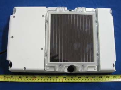
Click to zoom
Application Details
- Equipment Class
- PCB - PCS Licensed Transmitter
- Date of Grant
- Jan 26, 2012
- Application Purpose
- Original Equipment
- Date of Application
- Jan 24, 2012
- Equipment Note
- Trailer Tracks Service
- Frequency Range
- 1852.40000000 - 1907.60000000
- Company
- Qualcomm Technologies, Inc.
- Country
- United States
Documents & Files
Document Text
Text extracted from the exhibit documents filed with the FCC. Open a document above to read the original.
Users Manual
80-J7615-1 Rev. AMAY CONTAIN U.S. AND INTERNATIONAL EXPORT CONTROLLED INFORMATION4-1 4 TT210 Installation Planning Important Notes Note Refer to Chapter 3: General Wiring Guidelines, while planning your installation. The cable chapter provides specific information on cables and wiring and should be considered during the installation planning stage. Note Installers should be familiar with basic automotive wiring. It is recommended that installation personnel complete the appropriate Qualcomm training courses prior to installing the TT210 system. Regulatory Compliance Information FCC/IC Compliance Statement This device complies with part 15 of the FCC Rules. Operation is subject to the following two conditions: (1) This device may not cause harmful interference, and (2) This device must accept any interference received, including interference that may cause undesired operation. Le présent appareil est conforme aux CNR d'Industrie Canada applicables aux appareils radio exempts de licence. L'exploitation est autorisée aux deux conditions suivantes : (1) l'appareil ne doit pas produire de brouillage, et (2) l'utilisateur de l'appareil doit accepter tout brouillage radioélectrique subi, même si le brouillage est susceptible d'en compromettre le onctionnement. Caution This equipment should be installed and operated with minimum 20 cm between the radiator and body. This transmitter must not be collocated or operating in conjunction with any other antenna or transmitter unless authorized to do so by the FCC/IC. General Installation InformationTT210 Installation Planning 4-2 MAY CONTAIN U.S. AND INTERNATIONAL EXPORT CONTROLLED INFORMATION80-J7615-1 Rev. A General Installation Information Consider the following information while planning a TT210 system installation. Any changes or modifications not expressly approved by Qualcomm could void the user’s authority to operate this equipment Verify the Trailer/Container Is in Good Condition Before beginning an installation: • Thoroughly evaluate the area prior to installation to ensure the area where the installation will take place is in good condition. Determine if the TT210 system can be installed on the trailer/container. The following are some deterrents that can impact an installation or result in additional procedures: - The trailer/container-nose plywood goes all the way to the roof. - The vertical support rails are too narrowly placed. - There is obvious and extreme damage to the trailer/container nose at the TT210 system installation area. • The trailer/container top rail above the 7-way should be flat and free of bends or deep dents. • The trailer skin above the 7-way, about an inch from the top rail, should be sturdy and free of any serious damage. • The 7-way connection points should be inspected for general cleanliness and corrosion. • Verify that there is voltage on pin 7 and at all 7-way connection points when external power is applied. Survey the Trailer/Container Survey the trailer/container and decide where exactly to install the hardware. Typically in dry van installations, the terminal is in the 7-way bay and the cargo sensor is in the adjacent bay. Terminal and Cables Make sure that the TT210 system terminal and cable locations do not hinder normal operation or maintenance of the trailer/container. Also make sure the TT210 system terminal and cables are installed and/or stored safely out of the way of possible damage by cargo or other factors. What to Consider Before Installing the System • Drill holes only when necessary and in concurrence with the customer. • Qualcomm recommends you use existing holes on the trailer/container for cable routing whenever possible. • Use silicone (RTV) sealant when necessary to prevent leakage. 80-J7615-1 Rev. AMAY CONTAIN U.S. AND INTERNATIONAL EXPORT CONTROLLED INFORMATION4-3 TT210 Installation PlanningInstallation Guidelines Installation Guidelines When making installation decisions, consider safety, security, quality and reliability, and accessibility. Safety, Reliability, and Accessibility • Use eye protection when using a drill or performing work that poses any hazard to the eyes. • Use ear protection in a noisy working area. • Wear appropriate clothing or uniforms and safety shoes. • Make sure you know what is behind the area before you drill. • Make sure ladders and portable scaffolding are in good condition. • Place ladders in safe positions. • Install equipment so it will not cause damage to the trailer/container or hardware over time or will work loose over time. • Make sure there are no loose components/cables and no unsecured components. • Use solid mounting surfaces. • Install all components in a location where they will not be abused. • Route all cables away from sharp or abrasive areas where they might become damaged. • Choose a location where components are safe from tampering. • Choose a location where future maintenance can be easily serviced. Typical TT210 Installation Sequence Trailers, containers, and flatbeds often differ from manufacturer to manufacturer. The TT210 system was designed to work with a variety of trailer/container types, however, every installation is unique and should be thoroughly planned out before implementation. 1.Identify the installation location. 2.Mount the unit. 3.Route and connect cables and wires. 4.Identify which cargo sensor mount to use. • If 3” from the skin to liner, use internal mount • if between 2” and 3” from skin to liner, use 1” pan • if container or plate nose or less than 2”, use the 3” pan 5.Install the optional cargo sensor and/or door sensor if desired. 6.Install battery into unit. Tools and Supplies Needed for InstallationTT210 Installation Planning 4-4 MAY CONTAIN U.S. AND INTERNATIONAL EXPORT CONTROLLED INFORMATION80-J7615-1 Rev. A 7.Close the unit. 8.Use the configuration tool software to configure the TT210 system and to verify the system is working properly. The software is also used to diagnose any problems with the system. 9.Pe…
Text truncated - open the document above for the full version.
Cover Letter(s)
2206 Ringwood Avenue San Jose, CA 95131 Tel: 408-526-1188 Fax: 408-526-1088 Email: [email protected] Project and Product Certification Representative Authorization Letter Reason for Amendment (current / obsolete) Revision History Approved Date From To Initial Release (current) 1.0 1.0 Nov-14-2006 Revised wording (current) 1.0 2.0 Sept–25-2007 QUALCOMM Incorporated 5775 Morehouse Drive San Diego, CA 92121-1714 www.qualcomm.com SCS-F18: Project and Product Certification Representative Authorization Letter Page 2 of 2 Rev 2.0 January 12, 2012 To: SIEMIC, INC. 2206 Ringwood Avenue, San Jose, CA 95131 USA Dear Sir/Madam, Re: Project and Product Certification Representative Authorization Letter We, Qualcomm Inc hereby authorize SIEMIC, INC. to act as a Certification Body for certifying for the following project(s): (TT210 3G) We affirm that between SIEMIC and Qualcomm Inc, any difference in understanding, including test plan, measurement methods, applicable standards and relevant procedures and processes have been resolved prior to commencement of testing activities. Sincerely, Fang Han Senior Staff Engineer Qualcomm Incorporated
Cover Letter(s)
2206 Ringwood Avenue San Jose, CA 95131 Tel: 408-526-1188 Fax: 408-526-1088 Email: [email protected] Confidentiality Request Letter Reason for Amendment (current / obsolete) Revision History Approved Date From To Initial Release (current) 1.0 1.0 Nov-14-2006 Adding CFR 2.459 1.0 2.0 August – 11 - 2008 QUALCOMM Incorporated 5775 Morehouse Drive San Diego, CA 92121-1714 www.qualcomm.com SCS-F19: Confidentiality Request Letter Page 2 of 3 Rev 2.0 January 12, 2012 To: Federal Communications Commission Authorization and Evaluation Division 7435 Oakland Mills Road Columbia, MD 21046 Subject: Permanent Confidentiality Request for FCC ID: J9CTT210Q1WW2 We hereby request confidential treatment of information accompanying this application as outlined below: Name Exhibit Type Sierra Wireless modular Operation Description Operation Description & Documentation Sierra Wireless modular Block Diagram Block Diagram Sierra Wireless modular Parts List and Tune-up procedure Parts List and Tune-up Procedure Sierra Wireless modular Schematic Schematic System/Bluetooth Operation Description Operation Description & Documentation System/Bluetooth Block Diagram Block Diagram System/Bluetooth Parts List Parts List and Tune-up Procedure System/Bluetooth Module Schematic Schematic The above materials contain trade secrets and proprietary information not customarily released to the public. The public disclosure of these materials may be harmful to the applicant and provide unjustified benefits to its competitors. The applicant understands that pursuant to Section 0.457 & 0.459 of the Rules, disclosure of this application and all accompanying documentation will not be made before the date of the Grant for this application. Sincerely, Fang Han Senior Staff Engineer QUALCOMM Incorporated 5775 Morehouse Drive San Diego, CA 92121 (858) 845-3078, [email protected] QUALCOMM Incorporated 5775 Morehouse Drive San Diego, CA 92121-1714 www.qualcomm.com SCS-F19: Confidentiality Request Letter Page 3 of 3 Rev 2.0 January 12, 2012 To: Federal Communications Commission Authorization and Evaluation Division 7435 Oakland Mills Road Columbia, MD 21046 Subject: Short Term Confidentiality Request for FCC ID: J9CTT210Q1WW2 To Whom It May Concern: Pursuant to sections 0.457 and 0.459 of CFR 47 and to avoid premature release of sensitive information prior to marketing or release of the product to the public, the applicant requests the following documents contained in this certification application be temporarily withheld from public disclosure for an initial period of 45 days: - Internal photos - User Manual The above materials contain trade secrets and proprietary information not customarily released to the public. The public disclosure of these materials may be harmful to the applicant and provide unjustified benefits to its competitors. Sincerely, Fang Han Senior Staff Engineer QUALCOMM Incorporated 5775 Morehouse Drive San Diego, CA 92121 (858) 845-3078, [email protected]
ID Label/Location Info
Niederhauser, Steven (sniederh) - 11/15/2011 09:05:47 AM PST Released Released
Internal Photos
EUT Cover off View 1 EUT Cover off Closer View 2 PCBA 1 Top View PCBA 1 Bottom View EUT Antenna Front View EUT Antenna Rear View
RF Exposure Info
MPE CALCULATION For Qualcomm Incorporated – Trailer Tracking Device FCC ID: J9CTT210Q1WW2 RF Exposure Requirements: 47 CFR §1.1307(b) RF Radiation Exposure Limits: 47 CFR §1.1310 RF Radiation Exposure Guidelines: FCC OST/OET Bulletin Number 65 EUT Frequency Band: 300 ~ 1500 MHz, 1500 ~100,000MHz Limits for General Population/Uncontrolled Exposure in the band of: 30MHz – 300MHz Power Density Limit: 0.2 mW/ cm 2 Equation: S = PG / 4πR 2 or R = √PG / 4πS Where, S = Power Density P = Power Input to Antenna G = Antenna Gain R = distance to the center of radiated antenna ______________________________________________________________________________________________________________________ Cellular ERP Power = 2356.55mW, MPE limit = 0.566mW/cm 2 By using equation R = √PG / 4πS R= 20cm Result The Above Result had shown that the minimum separation distance in order to meet MPE requirement is 0.468mW/cm 2 . PCS EIRP Power = 1258.930mW, MPE limit = 1mW/cm 2 By using equation R = √PG / 4πS R= 20cm Result The Above Result had shown that the minimum separation distance in order to meet MPE requirement is 0.250mW/cm 2 . Completed By: Dan Coronia Date: January 24, 2012
Test Report
QUALCOMM INCORPORATED TRAILER TRACKING DEVICE Model: TT210 3G January 19th 2012 Report No.: SL11112903(QCM(006_RF(FCC_22,24) (This report supersedes None ) This Test Report is Issued Under the Authority of: Dan Coronia Senior Compliance Engineer Leslie Bai Director of Certification Modifications made to the product : None This test report may be reproduced in full only. All Test Data Presented in this report is only applicable to presented Test sample. Title: RF Test Report of Qualcomm Incorporated Model : TT210 3G To FCC 22(H):2011 & FCC 24(E):2011& RSS'132 Issue 2 : 2005 & RSS'133 Issue 5 : 2009 Serial# SL11112903'QCM'006_RF(FCC_22,24) Issue Date January 19th 2012 Page 2 of 114 www.siemic.com Laboratory Introduction ON SIEMIC, headquartered in the heart of Silicon Valley, with superior facilities in US and Asia, is one of the leading independent testing and certification facilities providing customers with one'stop shop services for Compliance Testing and Global Certifications. In addition to testing and certification, SIEMIC provides initial design reviews and compliance management through out a project. Our extensive experience with China, Asia Pacific, North America, European, and international compliance requirements, assures the fastest, most cost effective way to attain regulatory compliance for the global markets . Accreditations for Conformity Assessment Country/Region Accreditation Body Scope USA FCC, A2LA EMC , RF/Wireless , Telecom , SAR Canada IC, A2LA, NIST EMC, RF/Wireless , Telecom , SAR Taiwan BSMI , NCC , NIST EMC, RF, Telecom , Safety Hong Kong OFTA , NIST RF/Wireless ,Telecom Australia NATA, NIST EMC, RF, Telecom , Safety Korea KCC/RRA, NIST EMI, EMS, RF , Telecom, Safety , SAR Japan VCCI, JATE, TELEC, RFT EMI, RF/Wireless, Telecom Mexico NOM, COFETEL, Caniety Safety, EMC , RF/Wireless, Telecom Europe A2LA, NIST EMC, RF, Telecom , Safety, SAR Accreditations for Product Certifications Country Accreditation Body Scope USA FCC TCB, NIST EMC , RF , Telecom Canada IC FCB , NIST EMC , RF , Telecom Singapore iDA, NIST EMC , RF , Telecom EU NB EMC & R&TTE Directive Japan MIC, (RCB 208) RF , Telecom HongKong OFTA (US002) RF , Telecom Title: RF Test Report of Qualcomm Incorporated Model : TT210 3G To FCC 22(H):2011 & FCC 24(E):2011& RSS'132 Issue 2 : 2005 & RSS'133 Issue 5 : 2009 Serial# SL11112903'QCM'006_RF(FCC_22,24) Issue Date January 19th 2012 Page 3 of 114 www.siemic.com This page has been left blank intentionally. Title: RF Test Report of Qualcomm Incorporated Model : TT210 3G To FCC 22(H):2011 & FCC 24(E):2011& RSS'132 Issue 2 : 2005 & RSS'133 Issue 5 : 2009 Serial# SL11112903'QCM'006_RF(FCC_22,24) Issue Date January 19th 2012 Page 4 of 114 www.siemic.com CONTENTS 1 EXECUTIVE SUMMARY & EUT INFORMATION ............................................................................................................ 6 2 TECHNICAL DETAILS.................................................................................................................................................. 7 3 MODIFICATION ........................................................................................................................................................... 8 4 TEST SUMMARY ......................................................................................................................................................... 9 5 MEASUREMENTS, EXAMINATION AND DERIVED RESULTS ..................................................................................... 10 ANNEX A. TEST INSTRUMENT & METHOD......................................................................................................................... 73 ANNEX B EUT AND TEST SETUP PHOTOGRAPHS ........................................................................................................... 77 ANNEX C. TEST SETUP AND SUPPORTING EQUIPMENT ................................................................................................... 77 ANNEX D USER MANUAL, BLOCK DIAGRAM, CIRCUIT DIAGRAM .................................................................................. 81 ANNEX E. SIEMIC ACCREDITATION CERTIFICATES ........................................................................................................... 82 Title: RF Test Report of Qualcomm Incorporated Model : TT210 3G To FCC 22(H):2011 & FCC 24(E):2011& RSS'132 Issue 2 : 2005 & RSS'133 Issue 5 : 2009 Serial# SL11112903'QCM'006_RF(FCC_22,24) Issue Date January 19th 2012 Page 5 of 114 www.siemic.com This page has been left blank intentionally. Title: RF Test Report of Qualcomm Incorporated Model : TT210 3G To FCC 22(H):2011 & FCC 24(E):2011& RSS'132 Issue 2 : 2005 & RSS'133 Issue 5 : 2009 Serial# SL11112903'QCM'006_RF(FCC_22,24) Issue Date January 19th 2012 Page 6 of 114 www.siemic.com 1 Executive Summary & EUT information The purpose of this test programmed was to demonstrate compliance of the Qualcomm Incorporated Model: TT210 3G against the current Stipulated Standards. The Trailer Tracking Device have demonstrated compliance with the FCC 22(H):2011, FCC 24(E):2011,RSS'132 Issue 2 : 2005, RSS'133 Issue 5 : 2009. The test has demonstrated that this unit complies with stipulated standards. EUT Information EUT Description : The Trailer Tracks service is the Qualcomm wireless systems for identifying and locating trailers and containers for the trucking industry. This service provides cost'effective wireless status monitoring and management of trailers and containers. The TT210 system sends status information over'the'air (OTA) to the customer using dual mode cellular functionality. The Trailer Tracks service is a comprehensive, end'to' end trailer/container identification and location systems, consisting of rugged mobile hardware, reliable network services, robust host software, and extensive data integration capabilities. The TT210 is a single unit with a WWAN antenna, GPS antenna, solar cell, and digital circuit board. The digital board includes…
Text truncated - open the document above for the full version.
Test Setup Photos
Radiated Emission Front View (30MHz-1GHz) Radiated Emission Rear View (30MHz-1GHz) Radiated Emission Front View above 1GHz Radiated Emission Rear View above 1GHz Conducted Emission Front View Conducted Emission Rear View
Contact Information
Applicant
Paul Guckian(Vice President, Regulatory Engineering)
Test Firm
Bureau Veritas Consumer Products Services, Inc.Sarb Shelopal
[email protected]+1 925 963 4420
Technical Specifications
| # | Rule Parts | Frequency Range | Power Output | Emission | Tolerance |
|---|---|---|---|---|---|
| 6 | 24E | 1.85 GHz - 1.91 GHz | 700.00 mW | 4M18F9W | 85 Hz |
Other Applications from Qualcomm Technologies, Inc.
J9C-M2X75
Aug 13, 2024Module
Equipment Class
CBE - Citizens Band End User DevicesJ9C-M2X72
Aug 13, 2024Module
Equipment Class
PCB - PCS Licensed Transmitter
J9C-QCNCM825
Aug 26, 2023Qualcomm WiFi 7/BT Combo module
Equipment Class
6CD - 15E 6 GHz Low Power Dual Client
J9C-QCNCM865
Apr 04, 2023Qualcomm WiFi 7/BT Combo module
Equipment Class
NII - Unlicensed National Information Infrastructure TX
J9CQCARD7280N
Nov 07, 2022QCARD7280
Equipment Class
DTS - Digital Transmission System