J9CTUTT-800Terrestrial Untethered TrailerTRACS
Qualcomm Technologies, Inc.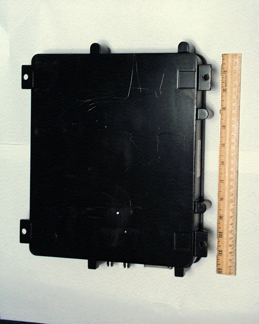
Click to zoom
Application Details
- Equipment Class
- TNB - Licensed Non-Broadcast Station Transmitter
- Date of Grant
- Mar 05, 2000
- Application Purpose
- Original Equipment
- Date of Application
- Nov 28, 1999
- Equipment Note
- Terrestrial Untethered TrailerTRACS
- Frequency Range
- 824.01000000 - 848.97000000
- Company
- Qualcomm Technologies, Inc.
- Country
- United States
Documents & Files
Document Text
Text extracted from the exhibit documents filed with the FCC. Open a document above to read the original.
Attestation Statements
TUTT-800 FCC CertificationFCC ID: J9CTUTT-800Attestation Statement QUALCOMM ProprietaryPage 2-1 2. Attestation Statement 1 The Terrestrial Untethered TrailerTRACS (TUTT), FCC ID J9CTUTT-800, is a 2 mobile station of a trailer tracking and monitoring system for data 3 communication with a fleet management center through the Advanced Mobile 4 Phone Service (AMPS) network. This equipment uses a CMM 8600 modem 5 (FCC ID APV0896) manufactured by Standard Communications for data 6 communications in cellular frequency band. 7 The equipment complies with uncontrolled RF exposure environment 8 requirement by the IEEE STD C95.1. 9 The data, data evaluation and equipment configuration represented herein for 10 equipment certification are a true and accurate representation of the 11 measurements of the sample’s radio frequency interference emissions 12 characteristics as of the dates and at the times of the test under the conditions 13 herein specified. This applies to all tests that do not require an Open Area Test 14 Site (OATS) to perform. Test that required an OATS site was performed by TUV 15 Product Services. 16 Equipment Tested:Terrestrial Untethered TrailerTRACS 17 Part Number:10-52675-10 18 Series Number:19999128 19 Dates of Test:November 8 – 22, 1999 20 Test Performed by:Fang Han, Senior Engineer 21 22 23 __________________________ 24 25
Cover Letter(s)
TUTT-800 FCC CertificationFCC ID: J9CTUTT-800Cover Letters QUALCOMM ProprietaryPage 1-1 1. Cover Letters 1 1.1 Equipment Authorization Application for 2 FCC ID J9CTUTT-800 3 TO: 4 Federal Communications Commission 5 Authorization and Evaluation Division 6 November 18, 1999 7 8 Re: Equipment Authorization Application for FCC ID J9CTUTT-8009 QUALCOMM herein submits the Application for Equipment Authorization (FCC 10 Form 731) and Exhibits for Certification of a piece of equipment, Terrestrial 11 Untethered TrailerTRACS (TUTT), FCC ID J9CTUTT-800. 12 Applicant:QUALCOMM, INC. 13 5775 Morehouse Drive 14 San Diego, CA 92121-1714 15 Manufacture:QUALCOMM, INC. 16 5775 Morehouse Drive 17 San Diego, CA 92121-1714 18 The TUTT is a mobile station of a trailer tracking and monitoring system for 19 data communication with a fleet management center through the Advanced 20 Mobile Phone Service (AMPS) network. This equipment uses a CMM 8600 21 modem (FCC ID APV896) manufactured by Standard Communications for data 22 communications in cellular frequency band. 23 24 Fang Han 25 Senior Engineer 26 Qualcomm Inc. 27 28
Cover Letter(s)
Cover LettersFCC ID: J9CTUTT-800TUTT-800 FCC Certification Page 1-2QUALCOMM Proprietary 1.2 Request of Confidentiality 1 TO: 2 Federal Communications Commission 3 Authorization and Evaluation Division 4 November 18, 1999 5 6 Re: Request of Confidentiality7 Pursuant to Sections 0.457 and 0.459 of the Commission’s Rules, the Applicant 8 hereby requests confidential treatment of the information accompanying this 9 Application as outlined below: 10 Description 11 All schematics/block diagrams 12 All parts lists 13 The above materials contain trade secrets and proprietary information not 14 customarily released to the public. The public disclosure of these matters might 15 be harmful to the Applicant and provide unjustified benefits to its competitors. 16 The Applicant understands that pursuant to Rule 0.457, disclosure of this 17 Application and all accompanying documentation will not be made before the 18 date of the Grant for this Application. 19 20 21 22 Jay Moulton 23 Director, Engineering 24 QUALCOMM, INC. 25 26 27 28 29 30 31 32
Cover Letter(s)
TUTT-800 FCC CertificationFCC ID: J9CTUTT-800Cover Letters QUALCOMM ProprietaryPage 1-3 1.3 Exhibit Description 1 The following documents in pdf format will be submitted electronically to FCC 2 for equipment authorization. 3 4 No.FCC Exhibit TypeExhibit DescriptionFile name (.pdf) 1Cover LettersEquipment authorization applicationCover letter_1 2Cover LettersRequest of confidentialityCover letter_2 3Cover LettersExhibit descriptionCover letter_3 4Attestation statementAttestation statementAttestation 5Operational DescriptionOperational descriptionOperational descript 6Technical ReportMeasurement data and test setupTech report 7RF Exposure InfoRF exposure analysisRF exposure 8Technical ReportTUV Product Service ReportTUV rep 9Block DiagramBlock diagram and clock informationBlock-Clock 10Parts List/Tune Up InfoPart listPart_list 11SchematicsSchematicsSchematics 12Label/location InformationLabel and location informationLabel 13External PhotoExternal photosExt photo 14Internal PhotoInternal photosInt photo 15Users GuideInstallation guideInstallation 5 6
Cover Letter(s)
ATT: Linda Elliott / Errol Chang Federal Communications Commission Authorization and Evaluation Division February 2, 2000 Re: Status of FCC ID J9CTUTT-800, CN: EA96088 This letter is to inquire the status of the above application for FCC certification that we filed in November 1999. We are now entering the production and market phase for this product. In our understanding, without getting FCC Grant, we could not ship this product to our customer and any delay in shipment would significant affect our business. So FCC’s early grant would be very important to our planned entrance to U.S. and overseas markets. Our product is primarily composed of a control board. This board controls transmission from a phone module made by Standard Communications. This phone module already has a FCC Grant (FCC ID APV0896). Our integration of the phone module into the control board does not change and degrade any RF feature of the phone module according our test. If you need further supporting information regarding this product, please let me know. We appreciate you taking time on this application and look forward to your early grant. Sincerely, Fang Han Regulatory Engineer Qualcomm Inc. phone: (858) 845-3078 email: [email protected] Encl. At 1/13/00, 08:02 AM -0800, you wrote: >It has been taken care of. There was a mistake is the second mailing from >the FCC. Their records do show that it has been paid. Item closed. > >Fang, could you write a cover letter explaining what had happened in that >it was cleared last week and then you received another email yesterday >indicated that it was not complete. The FCC whats to determine why this >happened, and it is going to be sent to the programmers as a glitch. Fax >the cover letter and a copy of yesterday's email to Bette Taube at (301) >344-2050. > > >thanks......................................jay m. > > >At 11:31 AM 1/12/00 -0800, Kim Newcomer wrote: >>Would it help out if we just paid this very insignificant fee again to >>finish this up. Then we can get a refund later. >>Kim >> >>At 09:42 AM 1/12/00 -0800, Fang Han wrote: >>>Jay, >>> >>>It seems that FCC couldn't trace the payment. Could you please take time to >>>look at it and provide the evidence that FCC asked for. They need either >>> >>>1) Date payment sent to Bank; or >>>2) If paid by check, check number. >>> >>>The attached files are the explanation that I uploaded on 1/5. Their status >>>page shows that this process has been completed. Don't know what's wrong >>>again with the payment. >>> >>>Thanks, --Fang >>> >>>At 1/12/00, 09:05 AM -0500, you wrote: >>>>To: Fang Han, Qualcomm Inc. >>>>From: Bette Taube >>>> [email protected] >>>> FCC Application Processing Branch >>>> >>>>Re: FCC ID J9CTCU-1900 >>>>Applicant: Qualcomm Incorporated >>>>Correspondence Reference Number: 11220 >>>>731 Confirmation Number: EA95550 >>>>Date of Original E-Mail: 12/28/1999 >>>> >>>> >>>>The fee payment of $610.00 for this application appears to have not been >>>>paid. Please provide evidence of payment as soon as possible: 1) Date >>>>payment sent to Bank; 2) If paid by check, check number. >>>> >>>>The items indicated above must be submitted before processing can continue >>>>on the above referenced application. Failure to provide the requested >>>>information within 60 days of the original e- mail date may result in >>>>application dismissal pursuant to Section 2.917 (c) and forfeiture of the >>>>filing fee pursuant to section 1.1108. >>>> >>>>DO NOT reply to this e-mail by using the Reply button. In order for your >>>>response to be processed expeditiously, you must upload your response via >>>>the Internet at www.fcc.gov, Electronic Filing, OET Equipment Authorization >>>>Electronic Filing. If the response is submitted through Add Attachments, a >>>>message which informs the processing staff that a new exhibit has been >>>>submitted must also be submitted via Submit Correspondence. Also, please >>>>note that partial responses increase processing time and should not be >>>>submitted. >>>> >>>>Any questions about the content of this correspondence should be >directed to >>>>the e-mail address listed below the name of the sender. >>> >>> >> > >
Cover Letter(s)
Federal Communications Commission Authorization and Evaluation Division March 1, 2000 Re: FCC ID J9CTUTT-800, 731 CN EA96088 This email is to inquire the status of Qualcomm's application of the above FCC ID product for equipment certification. It has been over 90 days since we filed the application in last November, and the pending application status at FCC homepage shows that both technical review and administrative review have beem completed by 2/25/00 and 12/3/99 respectively. As I wrote to FCC on 2/2/00, we are now entering the production phase for this product, and FCC’s early grant would be critical to our planned marketing. We appreciate your time on this application and look forward to your early approval. Sincerely, Fang Han Qualcomm Inc. 5775 Morehouse Drive, L-300D San Diego, CA 92121 (858) 845-3078 (work) (858) 845-2045 (fax) (858) 636-1142 (pager) [email protected]
External Photos
TUTT-800 FCC CertificationFCC ID: J9CTUTT-800TUTT External Photos QUALCOMM ProprietaryPage 12-1 12. TUTT External Photos 1 12.1 TUTT System Configuration 2 AMPS antenna GPS antenna Power and signal cables 3 TUTT External PhotosFCC ID: J9CTUTT-800TUTT-800 FCC Certification Page 12-2QUALCOMM Proprietary 12.2 TUTT Installation in a Trailer 1 2 TUTT-800 FCC CertificationFCC ID: J9CTUTT-800TUTT External Photos QUALCOMM ProprietaryPage 12-3 12.3 TUTT Setup in Chamber 1 2 3 TUTT External PhotosFCC ID: J9CTUTT-800TUTT-800 FCC Certification Page 12-4QUALCOMM Proprietary 1 12.4 TUTT Top-side Appearance 2 3 TUTT-800 FCC CertificationFCC ID: J9CTUTT-800TUTT External Photos QUALCOMM ProprietaryPage 12-5 12.5 TUTT Bottom-side Appearance 1 2 3
ID Label/Location Info
TUTT-800 FCC CertificationFCC ID: J9CTUTT-800Label and Location QUALCOMM ProprietaryPage 11-1 11. Label and Location 1 FCC ID label 2 Figure 11–1. Label and its location for FCC ID J9CTUTT-800 3 Label and LocationFCC ID: J9CTUTT-800TUTT-800 FCC Certification Page 11-2QUALCOMM Proprietary 1 Figure 11–2. Zoom-in FCC Identifier 2 3
RF Exposure Info
TUTT-800 FCC CertificationFCC ID: J9CTUTT-800RF Exposure QUALCOMM ProprietaryPage 6-1 6. RF Exposure 1 Table 6-1 gives a summary of the expected radiation exposure levels versus2 distance from the transmitter antenna using equation (6-1). The maximum ERP3 power 1.209 W in Table 5-2 is used in evaluation of the RF exposure level.4 22 4 64.1 4 D ERP D EIRP S ππ == (6-1)5 where S is power density at distance D from the antenna. For near field,6 equation (6-1) could be used as “worst case” or conservative prediction 1 .7 Table 6–1. RF exposure level versus distance 8 Distance (cm) 1050100 MPE (mW/cm 2 ) 0.9620.0380.010 Table 5-1 shows that the RF exposure level complies with the uncontrolled9 exposure environment defined by IEEE STD C95.1. In real application, the10 transmission antenna shall be mounted on a trailer roof and will be at least 211 meter apart from the ground level. In normal operation, the TUTT will be12 transmitting message data for 3-5 seconds every few hours. Thus, the actual13 duty cycle of the transmitter is very small and there would be no RF exposure14 risk from this product.15 16 1 FCC OET Bulletin, No. 65, Edition 97-01, “Evaluating Compliance with FCC Guidelines for Human Exposure to Radiofrequency Electromagnetic Fields”, August 1997.
Test Report
TUTT-800 FCC CertificationFCC ID: J9CTUTT-800Measurement Procedures QUALCOMM ProprietaryPage 4-1 4. Measurement Procedures 1 4.1 List of Test Equipment and Accessories 2 1. PC with FCC.exe software for activating continuous transmission mode 3 2. TUTT accessories test box 4 3. Spectrum Analyzers 5 • HP8563E spectrum analyzer 6 • HP8593EM spectrum analyzer 7 4. Leader regulated DC power supply 8 4.2 Measurement Procedures 9 4.2.1 Conducted RF Power Output 10 Definition - The output power rating of the transmitter is the power available 11 at the output terminal of the antenna cable when the terminal is connected to 12 the normal load. 13 HP 8563E Spectrum Analyzer DC Power PC for Tx command Qualcomm TUTT TX command AMPS antenna cable accessories box 14 Figure 4–1. Measurement setup for conducted RF power 15 Method of Measurement - The transmitter output carrier power with SAT+ST 16 modulation was measured using an HP 8563E spectrum. The measurement 17 setup diagram is shown in Fig. 4-1. 18 Measurement ProceduresFCC ID: J9CTUTT-800TUTT-800 FCC Certification Page 4-2QUALCOMM Proprietary Minimum Standard - The transmitter output power shall be maintained 1 within range of –4dB to 2dB. 2 4.2.2 Radiated RF Power Output 3 Refer to TUV Product Service Test Report for test method and setup for radiated 4 RF power output. 5 4.2.3 Occupied Bandwidth 6 Definition –The occupied bandwidth is defined as the spectrum noise produced 7 at discrete frequency separations from the carrier due to all sources of unwanted 8 noise within the transmitter in a modulated condition. 9 Method of Measurement – Pursuant to CFR 47 session 22.917(h), use a HP 10 8593EM spectrum analyzer to measure the bandwidth under SAT+ST condition. 11 The measurement setup diagram is shown in Fig. 4-2. 12 HP 8593EM Spectrum Analyzer DC Power PC for Tx command Qualcomm TUTT TX command AMPS antenna cable accessories box 13 Figure 4–2. Measurement setup for Occupied Bandwidth 14 Minimum Standard - The mean power of emissions from the transmitter with 15 modulated carrier shall be attenuated below the mean power of the non- 16 modulated carrier in accordance with CFR 47 session 22.917(d). 17 4.2.4 Conducted Spurious Emissions 18 Definition - The conducted harmonic and spurious emissions are emissions at 19 the antenna terminals at a frequency or frequencies that are outside the 20 authorized bandwidth of the transmitter. 21 Method of Measurement - The transmitter shall be modulated with SAT, ST, 22 and SAT+ST. The measurement was made with a HP 8563E spectrum analyzer 23 from the lowest radio frequency generated in the equipment to the 10th 24 harmonic of the carrier. The measurement setup diagram is shown in Fig. 4-3. 25 TUTT-800 FCC CertificationFCC ID: J9CTUTT-800Measurement Procedures QUALCOMM ProprietaryPage 4-3 Minimum Standard - Conducted harmonic and spurious emissions shall be 1 attenuated below the level of emissions of the carrier in accordance with CFR 47 2 session 22.917(d). 3 HP 8563E Spectrum Analyzer DC Power PC for Tx command Qualcomm TUTT TX command AMPS antenna cable accessories box 4 Figure 4–3. Measurement setup for conducted spurious emissions 5 4.2.5 Radiated Spurious emissions 6 Definition - The radiated spurious emissions are emissions from the TUTT unit 7 with the attached antenna assembly. The radiated spurious emissions include 8 those emissions radiated from the attached antenna as well as the equipment 9 cabinet and attached cables. 10 Method of Measurement - The radiated emission measurement shall be 11 conducted at a FCC certified lab test site with a search antenna, which is 12 movable vertically and rotatable 90 degrees for vertically and horizontally 13 polarized signals. Refer to TUV Product Service Test Report for detailed 14 measurement setup 15 Minimum Standard - Radiated spurious emissions shall be attenuated below 16 the maximum level of emission of the carrier by at least )(log 1043P+ dB, in 17 which, P is mean output power in Watts. 18 4.2.6 Frequency Stability 19 Definition - The frequency stability is the ability of the transmitter to maintain 20 an assigned carrier frequency against variation in ambient temperature and 21 power supply. 22 Method of Measurement - Use the spectrum analyzer to sample the 23 transmitter RF output signal and measure its frequency under each specific 24 temperature and power supply condition. Vary the ambient temperature from - 25 30 to +60 ° C, and also vary the DC supply voltage to the equipment from 9.6 to 26 14.4 V at each temperature. The measurement setup is shown in Fig. 4-4. 27 Measurement ProceduresFCC ID: J9CTUTT-800TUTT-800 FCC Certification Page 4-4QUALCOMM Proprietary Minimum Standard - The transmitter carrier frequency shall be maintained 1 within ± 2.5 ppm. 2 HP 8563E Spectrum Analyzer DC Power PC for Tx command Qualcomm TUTT TX command AMPS antenna cable accessories box Temperature chamber 3 Figure 4–4. Measurement setup for frequency stability 4 5 TUTT-800 FCC CertificationFCC ID: J9CTUTT-800Measurement Results QUALCOMM ProprietaryPage 5-1 5. Measurement Results 1 5.1 Transmitter RF Power Output 2 5.1.1 Conducted RF Power Output 3 The conducted RF power output is tested per Part 2.1046(a). The RF output 4 power was measured using a HP 8563E Spectrum Analyzer. The antenna cable 5 of the equipment is terminated to a 50 ohms resistive load of the Spectrum 6 Analyzer. The nominal power from the CMM 8600 modem module (FCC ID: 7 APV0896) manufactured by Standard Communication Corporation is 1.2W. The 8 power level measured represents the actual power at the antenna port. Table 5- 9 1 shows the measured conducted power output at carrier mode. 10 Table 5–1. Conducted RF power output at antenna port 11 RF power (W)Transmission Channel Carrier frequency (MHz) CarrierSAT+ST 991824.040.9610.681 380836.401.2580.851 799848.970.6310.430 5.1.2 Radiated RF Power Output 12 The maximum effective radiated power of the TUTT integrating CMM 8600 13 modem module is calcul…
Text truncated - open the document above for the full version.
Test Report
TÜV PRODUCT SERVICE 10040 Mesa Rim Road San Diego, CA 92121-2912 Phone 858 546 3999 FAX 858 546 0364 Report No. 9553-06 Page 1 of 8 Rev.No 1.0 EMC EMISSION - TEST REPORT UNITED STATES STANDARD 47 CFR PART 2, SUBPART J 1 Test Report File No.:9553-06Date of Issue: 22 November 1999 Model / Serial No.:10-52675-10 / 19999128 Product Type: TUTT 2 Applicant: QUALCOMM, INC. Manufacturer: QUALCOMM, INC. License holder: QUALCOMM, INC. Address: 5775 Morehouse Drive, L-300D : San Diego, CA 92064 Test Result:nn Positiveoo Negative Test Project Number Reference(s): 9553-06 Total pages - Test Report:8 1 Paragraph 2.1053 2 With AMPS modem made by Standard Communication. NOTE: All test equipment used during testing is calibrated and traceable to NIST. TÜV Product Service reports apply only to the specific sample tested under stated test conditions. It is the manufacturer’s responsibility to assure the continued compliance of production units of this model. TÜV Product Service, Inc. shall have no liability for any deductions, inferences or generalizations drawn by the client or others from TÜV Product Service, Inc. issued reports. This report is the confidential property of the client. As a mutual protection to our clients, the public and ourselves, extracts from the test report shall not be reproduced except in full without our written approval. This report shall not be used by the client to claim product endorsement by NVLAP or any agency of the US government. TÜV Product Service, Inc. and its professional staff hold government and professional organization certifications and are members of AAMI, ACIL, AEA, ANSI, IEEE, NVLAP, and VCCI TÜV PRODUCT SERVICE 10040 Mesa Rim Road San Diego, CA 92121-2912 Phone 858 546 3999 FAX 858 546 0364 Report No. 9553-06 Page 2 of 8 Rev.No 1.0 DIRECTORY - EMISSIONS Test Report Pages Test Report1 - 8 Directory2 Test Regulations3 General Remarks and Summary8 Equipment Spurious Emissions5 Technical Documentation Test Data Sheets and Test Setup Drawing(s)TD1 Appendices Appendix AA1 Test Setups (Photographs) Appendix BB1 Product Information Form(s) Appendix CC1 Change History Appendix DD1 Supplemental Information TÜV PRODUCT SERVICE 10040 Mesa Rim Road San Diego, CA 92121-2912 Phone 858 546 3999 FAX 858 546 0364 Report No. 9553-06 Page 3 of 8 Rev.No 1.0 EMISSIONS TEST REGULATIONS : The emissions tests were performed according to the following regulations: o - EN 50081-1 / 1991 o - EN 55011 / 1991o - Group 1o - Group 2 o - Class Ao - Class B o - EN 55014 / 1993o - Household appliances and similar o - Portable tools o - Semiconductor devices o - EN 55022 / 1987o - Class Ao - Class B o - EN 55022 / 1998o - Class Ao - Class B o - VCCIo - Class A ITEo - Class B ITE n - 47 CFR Part 2, Subpart J n - 2.1053 o - AS/NZS 3548: 1995o - Class Ao - Class B o - CISPR 11 (1990) o - Group 1o - Group 2 o - Class Ao - Class B o - CISPR 22 (1998) o - Class Ao - Class B TÜV PRODUCT SERVICE 10040 Mesa Rim Road San Diego, CA 92121-2912 Phone 858 546 3999 FAX 858 546 0364 Report No. 9553-06 Page 4 of 8 Rev.No 1.0 Environmental Conditions In The Laboratory: Actual Temperature:: 23 °C Relative Humidity:: 50 % Atmospheric Pressure:: 100.0 kPa Power Supply Utilized: Power supply system: 12 Vdc Symbol Definitions: n -Applicable o -Not Applicable TÜV PRODUCT SERVICE 10040 Mesa Rim Road San Diego, CA 92121-2912 Phone 858 546 3999 FAX 858 546 0364 Report No. 9553-06 Page 5 of 8 Rev.No 1.0 Emissions Test Conditions: Field Strength of Spurious Radiation, Part 2, Paragraph 2.1053 The measurements were tested at the following test location : oo - Test not applicable n - Roof (Small Open Area Test Site) (Calibration Due Date: 28 May 2000) o - Canyon #1 (10- and 30-Meter Open Area Test Site), Carroll Canyon, San Diego (Calibration Due Date: 03 September 2000) o - Canyon #2 (3- and 10-Meter Open Area Test Site), Carroll Canyon, San Diego (Calibration Due Date: 20 May 2000) Testing was performed at a test distance of : n - 3 meters o - 10 meters o - 30 meters Test Equipment Used : Model No.Prop. No.DescriptionManufacturerSerial No.Cal Date AMF-3D-010180-35-10P752PreamplifierMiteq61434405/99* FF6549-1777Cellular Band FilterSage004N/A AA-190-06.00.0728CablesUnited Microwave--10/99** AA-190-30.00.0732CablesUnited Microwave--10/99** 3115453Double Ridge Guide AntennaEMCO9412-436410/01 8566B720/721Spectrum Analyzer & DisplayHewlett Packard2115F0084 2 03/00 Remarks: One year calibration cycle for all test equipment. (*) Preamplifier verification date. (**) Cable verification date. TÜV PRODUCT SERVICE 10040 Mesa Rim Road San Diego, CA 92121-2912 Phone 858 546 3999 FAX 858 546 0364 Report No. 9553-06 Page 6 of 8 Rev.No 1.0 Equipment Under Test (EUT) Test Operation Mode - Emissions Tests : The equipment under test was operated under the following conditions during emissions testing: o - Standby o - Test Program (H - Pattern) o - Test Program (Color Bar) o - Test Program (Customer Specified) o - Practice Operation o - Normal Operating Mode n -SAT+ST mode, transmit power 1.2W Configuration of the equipment under test: o - See Constructional Data Form in Appendix B - Page B2 n - See Product Information Form(s) in Appendix B - Page B2 The following peripheral devices and interface cables were connected during the testing: o -Type : o -Type : o -Type : o -Type : o -Type : o -Type : o -Type : o -Type : o - unshielded power cable o - unshielded cables o -shielded cablesMPS.No.: o - customer specific cables o - o - TÜV PRODUCT SERVICE 10040 Mesa Rim Road San Diego, CA 92121-2912 Phone 858 546 3999 FAX 858 546 0364 Report No. 9553-06 Page 7 of 8 Rev.No 1.0 Emissions Test Results: Spurious Radiation, Part 2, Paragraph 2.1053 nn - PASSoo - FAILoo - NOT APPLICABLE Minimum limit margin0.2dBat1648.08MHz Maximum limit exceedingdBatMHz Remarks: TÜV PRODUCT SERVICE 10040 Mesa Rim Road San Diego, CA 92121-2912 Phone 858 546 3999 FAX 858 546 0364 Report No. 9553-06 Page 8 of 8 Rev.No 1.0 GENERAL REMARKS: NOTE: All photographs are representative…
Text truncated - open the document above for the full version.
Contact Information
Applicant
Paul Guckian(Vice President, Regulatory Engineering)
Technical Contact
Qualcomm Inc.Fang Han
[email protected](858) 845-3078
5775 Morehouse Drive · San Diego, California · United States
Test Firm
TUV AmericaJames Owen
Technical Specifications
| # | Rule Parts | Frequency Range | Power Output | Emission | Tolerance |
|---|---|---|---|---|---|
| 1 | 22 | 824.01 MHz - 848.97 MHz | 1.2 W | 40K0F1D | 2.5000000000 ppm |
Other Applications from Qualcomm Technologies, Inc.
J9C-M2X75
Aug 13, 2024Module
Equipment Class
CBE - Citizens Band End User DevicesJ9C-M2X72
Aug 13, 2024Module
Equipment Class
PCB - PCS Licensed Transmitter
J9C-QCNCM825
Aug 26, 2023Qualcomm WiFi 7/BT Combo module
Equipment Class
6CD - 15E 6 GHz Low Power Dual Client
J9C-QCNCM865
Apr 04, 2023Qualcomm WiFi 7/BT Combo module
Equipment Class
NII - Unlicensed National Information Infrastructure TX
J9CQCARD7280N
Nov 07, 2022QCARD7280
Equipment Class
DTS - Digital Transmission System