JLF-HS1Wireless Headset Earpiece
Chamberlain Wireless Products Inc.
Click to zoom
Application Details
- Equipment Class
- DXT - Part 15 Low Power Transceiver, Rx Verified
- Date of Grant
- Jul 06, 2004
- Application Purpose
- Original Equipment
- Date of Application
- Mar 02, 2004
- Equipment Note
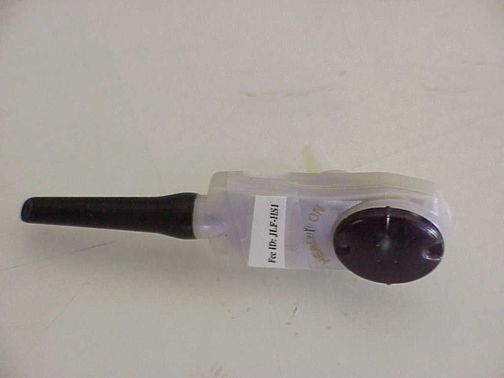
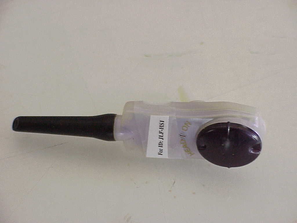
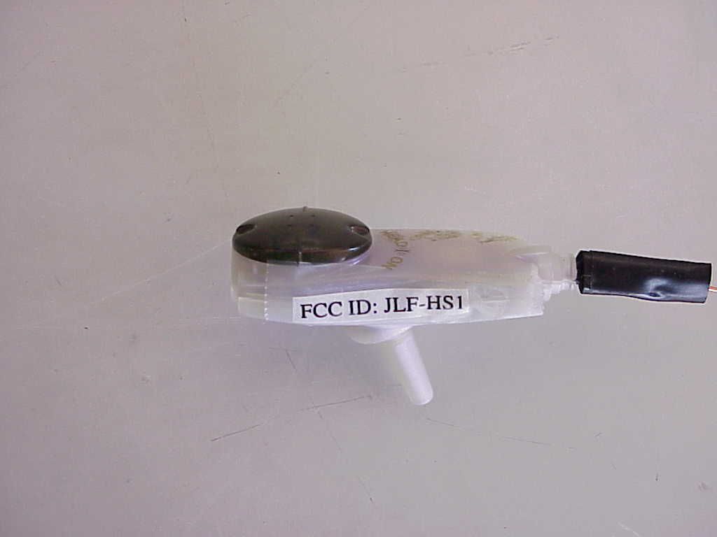
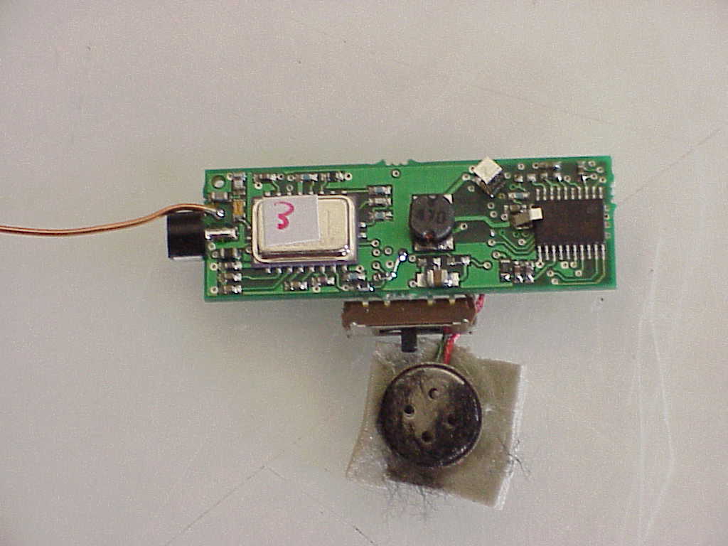
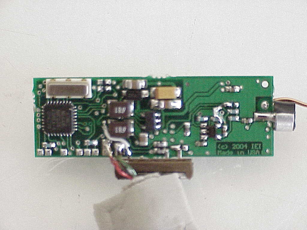
- Wireless Headset Earpiece
- Frequency Range
- 916.50000000 - 916.51000000
- Country
- United States
Documents & Files
Document Text
Text extracted from the exhibit documents filed with the FCC. Open a document above to read the original.
Users Manual
3 Silver Rings HeadOn® Users Manual v1.0 091703 Thank you for your purchase of HeadOn Wire-Free wireless headset system. This pr oduct has been meticulously designed to provide the user with unsurpassed comfort and usability and years of trouble-free service. About the manufacturer... International Electronics, Inc ha s been a USA designer and manufacturer of high quality consumer and professional electronic products since 1985. The HeadOn has been a cumulative effort of thousands of hours of engineering and fine-tuning, assuri ng that the product is especially comfor table for all day use and still remain conveniently small and unobtrusive. IEI ma nufacturers all of its products in th e USA with the highest quality robotics and a best trained staff. The best enjoy the benefits of HeadOn, pl ease read this document carefully. This will assure the proper operation of the HeadOn as well as your satisfaction. Cell Phone Compatibility: HeadOn is compatible with all cell phone s, which have a “Round, 2.5mm Standard 3 Ring Headset Plug”. Simply look at the plug on your “wired” headset for your cellphone. It should be cylindrical in shape and have 3 meta l rings and 2 black pl astic rings. Most ph ones have been designed with this type of headset plug. So me Nokia models may have a similar plug, but they have an extra ring of silver and b lack. If you have a Nokia phone with this arrangement, please purchas e an inexpensive converter available at your local phone accessory store. List Of Known Compatible Phones: Please see www.headonwireless.com for an updated compatibility list. All Phones Available At RadioShack ™. All Sprint PCS™ Phones. Audiovox: Kyocera LG Motorola Nextel Panasonic Samsung (Note: Some Samsung models may not work. Note the jack on th e phone. If it has a metal fitting on the outside ring of the conne ctor, this product will not work). Sanyo Virgin Battery Requirement: HeadOn requires the use of inexpensive Zinc Air batteries available at most locations . We strongly recommend the use of high qu ality batteries. FCC compatibility Statement This product complies with FCC regulation part 15. This product may not cause interference with other devices and this product must accept interference generated by other products. LockUnlock Battery Life: HeadOn features ultra low power technology, which combined with sophisticated fu ll duplex digital secure link can provide amazi ng talk time as well as unsurpassed stand-by times. Extreme temperatur es or high humidity can affect the battery life. (Leaving HeadOn or its batteries in a very hot or cold car may cause battery degradation). Talk time is based on the quality of the battery. HeadOn batteries pr oduce the longest talk time of 80 hours. Other batteries m ay last as long as 40 hours of talk time. * * Talk Time: Up to 80 Hours of intermitte nt use, or 60 hours of continuous us e (Speaking 60 hours without stopping!). Stand-By time: Up to 2000 hours (3 months) with normal daily use. Replacing the Batteries: Please take care not to over-twist the battery doors. See diagram: Remove protective backing from battery. WAIT 3 MINUTES BEFORE USING THE BATTERY . ! (Do not remove the backing more than a few days ahead of use. Once the backing is removed, the life of the battery will start a 90-day countdown). This battery technology contains no compone nts harmful to the environment. They may be disposed of in the trash. Low Battery Warning: HeadOn features a distinctive lo w battery beep for each of the components. The H ead Set with low battery will generate a single “Beep Tone” every 15 seconds. The Base Unit will generate Two Beep Tones when its ba ttery needs replacement. Please note that the tone for both devi ces is issued in your ear through the headset while you are communicatin g. There are no beeps issued otherwise. If the system does not operate after long stor age, replace the batteries with fresh ones. On-Off Control: HeadOn is the only product of its kind f eaturing Fully Automatic Operation. There ar e no On and Off switches on this system. Al l functions are Automatic. How the system turns On and Off: HeadOn is always “Asleep”. Wh en the base unit (unit attached to the phone) detects sounds comi ng from the telephone, it will awaken and wake the headset up w ithin 1 second. You may miss the first ½ sec ond of the sound of a ring or button press if the system has been asleep. If you remain on hold for an extensive period of time, and HeadOn does not detect any sounds from the telephone, it will go int o mid-sleep to save power. During this time, you will not notice any “Hiss” in the background. The system automatically mutes the headset and await any so und to be sent from the cell phone.... Upon which the HeadOn will re-establish communications within 1/50 of a second. All of these functions are automat ic and require no user input. Interference This product has been designed to minimize interference by the us e of digital – secure communica tion. In addition, the HeadOn s ystem utilize Narrow- Band RF connections to further reduce interference. Unlike BlueT ooth headsets, the HeadOn is not susceptible to interference fo rm Microwave ovens or Wireless Networking devices found in laptops. Additionally, this product is immune to interference from standard 2.4GHZ cordle ss phones found in households. • If you experience sound degradation in areas such as airports, simply rep osition the Dongle attachment on your cellphone and keep it closer to you. • If the connection is temporarily interrupted, simply reposition your head just a bit. This is due to reflections, which can cause “Null”, or “Void” areas, even when you are near the o ther transceiver unit. This is normal in the world of Radio Frequency, especially such low power devices as Head On and BlueTooth systems. Connecting To The Cellphone The Dongle portion of HeadOn can be mount ed to the phone in a veriety of ways; • Simply allow it to “Dangle “ freely. • Use the enclo…
Text truncated - open the document above for the full version.
Cover Letter(s)
International Electronics, inc. 5913C NE 127 th Ave, Suite 800 Vancouver, WA 98682 888-679-7994 April 14 2004 GME Attention Kyle Dear Kyle, Please notify FCC that the schematics and diagrams of the HeadOn are confidential and are marked as such. Please request that FCC removes these confidential documents from their web site and eliminate access to all of such. Thank you for your immediate attention, Sincerely, Shary Nassimi, President, IEI
Cover Letter(s)
Green Mountain Electromagnetics, Inc. GME (802)388-3390 Fax: (802)388-6279 Email: [email protected] 219 Blake Roy Road • Middlebury, VT 05753 4/26/04 Diane Poole FCC OET Dear Diane, Please regard the FCCID JLF-HS1 EA835321 HeadOn head set electrical schematic and block diagrams confidential. The system uses a proprietary design which is a company secret. If competing companies could access the design it would undercut a deal with a national distributor and cripple the business. Neither item is available to anyone outside the technical team on the project. Sincerely, Kyle R. Kowalczyk President
Operational Description
HeadOn Theory Of Operation CONFIDENTIAL 1/25/04 Uses; HeadOn has been designed to allow any cordless or cellular telephone to become wireless to the headphone. The system is comprised of the Dongle, which is attached to the cellphone or cordless phone’s headset jack and the headset, which is inserted into the ear using soft foam ear gels. Theory of operation; HeadOn utilizes a digital data stream with preparatory ADPCM encoding of audio. The data is transmitted in short 800us bursts every 5 milliseconds. Data rate is 500kbps. The system is secure which connected and will not allow other devices to listen in. Precautions: Do not immerse in water. Contains loose parts, which can pose chocking hazard for children. Do not eat batteries. Operating temperature: -10 to +45 Centigrade.
Test Report
Serial No. GM24016f FCC ID: JLF-HS1 FCC TEST REPORT FOR THE INTERNATIONAL ELECTRONICS, INC. HEADON WIRELESS HEADSET EARPIECE Prepared for: International Electronics, Inc. 5913 NE 127 Ave. Suite 800 Vancouver, Washington 98682 Submitted by: Green Mountain Electromagnetics, Inc. (802) 388-3390 Fax: (802) 388-6279 E-mail: [email protected] 219 Blake Roy Road • Middlebury, Vermont 05753 Copyright: March 10, 2004 This report shall not be reproduced, except in full, without the written approval of GME. Accredited Cert 898.01 Serial No. GM24016f FCC ID: JLF-HS1 2 of 20 International Electronics, Inc. FCC Tests By Green Mountain Electromagnetics, Inc. Middlebury, Vermont Unit: HeadOn Wireless Headset Earpiece Evaluated: February 27 to March 9, 2003 I. Applicable Standards: The unit described in this report was measured for certification with the Code of Federal Regulations Chapter 47 – "Telecommunication, Part 2 – Frequency Allocations and Radio Treaty Matters: General Rules and Regulations, Subpart J – Equipment Authorization Procedures (2002)." Measurements required were per paragraphs 2.1046 RF Power Output, 2.1047 Modulation Characteristics, 2.1049 Occupied Bandwidth, 2.1051 Spurious Emissions at Antenna Terminals, 2.1053 Field Strength of Spurious Radiation, 2.1055 Frequency Stability, and 2.1093 Radiofrequency Radiation Exposure Evaluation: Portable Devices. The unit was also measured for verification of compliance with "CFR47, Part 15 – Radio Frequency Devices, Subpart C: Intentional Radiators, Paragraph 15.209, Radiated Emissions Limits and Paragraph 15.247/249, Operation within the bands 902-928 MHz, 2400-2483.5 MHz, and 5725-5850 MHz as applicable to digitally modulated intentional radiators (2002)." Measurement procedures were in accordance with ANSI C63.4, "Methods of Measurement of Radio-Noise Emissions from Low-Voltage Electrical and Electronic Equipment in the Range of 9 kHz to 40 GHz (2000)," and FCC OET Bulletin 65, "Evaluating Compliance with FCC Guidelines for Human Exposure to Radiofrequency Electromagnetic Fields (August 1997)." Serial No. GM24016f FCC ID: JLF-HS1 3 of 20 II. Unit Tested: The International Electronics, Inc. HeadOn wireless headset earpiece is the portion of the wireless headset worn on the user. The HeadOn uses DC power and has a digitally modulated 916 MHz transmitter and receiver. It consists of the three-piece plastic enclosure with speaker hardware, the transmit/receive circuits, the electronics, and the antenna. The table below describes the unit tested to determine compliance with the standards: Model/P/NManufacturerH/W/D in cmSerial Number HeadOn EarpieceInternational Electronics, Inc. 8/3/2ENG001 The highest frequency investigated is ten times the HeadOn highest fundamental (9.16 GHz). III. Measurement Location: The GME laboratory and Open Area Test Site (OATS) are located at 219 Blake Roy Road, Middlebury, VT. The OATS is a 3-meter site complete with antenna positioner, ground plane and motorized turntable. The OATS is constructed in accordance with ANSI C63.7-1992 and complies with the requirements for radiated emissions testing in ANSI C63.4-2000 and CISPR 16-1993. The electromagnetic laboratory is constructed in accordance with CE immunity standards and ANSI C63.4-2000 (conducted emissions). GME is internationally accredited by the American Association for Laboratory Accreditation (A2LA) and meets the quality requirements in ISO/IEC 17025 (1999), "General Requirements for the Competence of Testing and Calibration Laboratories." Serial No. GM24016f FCC ID: JLF-HS1 4 of 20 IV. Summary of Results: The International Electronics, Inc.HeadOn wireless headset earpiece complies with the requirements in CFR 47, Paragraphs 2, and 15. Section IX contains the results summarized in the table below. CFR 47FrequencySpecifiedMeasured TestMode/PortParagraphRange/LevelValuesValues 1Carrier PowerTransmit2.1046 15.247d 916 MHz< 8 dBm-10 dBm 2Modulation Characteristics Transmit2.1047 15.247a2 500 kHz from carrier >6 dB10 dB 3Occupied Bandwidth Transmit2.1049 15.247c 100 kHz from edge of band >20 dB>20 dB 4Conducted Spurious Receive/ Transmit 2.10511 MHz to 9.16 GHz attenuation >20 dB >20 dB 5Frequency Tolerance Transmit2.1055Battery End Point1.5 V916 MHz 6Radiated Emissions Enclosure15.209 15.249 2.1053 1.705 - 30 MHz 30 - 88 MHz 88 - 216 MHz 216 - 960 MHz 960 - 916 MHz 916 (Fund) 49.5 dBuV/m 40 dBuV/m 43.5 dBuV/m 46 dBuV/m 54 dBuV/m 94 dB uV Within All Limits at 3meters 7Exposure Evaluation Enclosure2.1093916.4 MHz0.08W/kg Body 1.6 W/kg 1g Vol Within All Limits Testing was performed by Kyle R. Kowalczyk, president, Green Mountain Electromagnetics and requested by: International Electronics, Inc. 5913 NE 127 Ave. Suite 800 Vancouver, WA 98682 ___________________________ Kyle R. Kowalczyk 3/10/04 Serial No. GM24016f FCC ID: JLF-HS1 5 of 20 V. Measuring Equipment: The table below describes the instrumentation used by Green Mountain Electromagnetics to perform this testing: UnitManufacturerModelSerial #Last Cal.Next Cal. Spectrum Analyzer Hewlett- Packard 85923624A006311/13/041/13/05 AmplifierHewlett- Packard 8447 D2944A073134/01/034/01/04 Signal GeneratorHewlett- Packard E4421BUS3822019510/17/0310/17/04 PlotterHewlett- Packard 7475A2517A05281n/an/a Broadband E-field Antenna Antenna Research Associates LPB-2513/A112510/2/0310/2/04 Serial No. GM24016f FCC ID: JLF-HS1 6 of 20 VI. Equipment and Cable Configuration: GME witnessed the unit in satisfactory condition for testing, however the manufacturer is responsible for ensuring that the equipment under test (EUT) represents the product line. The manufacturer is also responsible for the EMC test plan and for assuring that this report is consistent with that plan. The EUT configuration was arranged to produce maximum radiated emissions as shown in the block diagram below, as well as in the photograph in Section VIII. The equipment was subjected to complete emissions tests. Figure 1 – Block Diagram of EUT on Turntable The EUT…
Text truncated - open the document above for the full version.
Contact Information
Applicant
Barbara Kelkhoff(Manager of Regulatory Affairs)
Technical Contact
Green Mountain ElectromagneticsKyle R Kowalczyk
[email protected]802-388-3390
219 Blake Roy Road · Middlebury · United States
Non-Technical Contact
Green Mountain ElectromagneticsKyle R Kowalczyk
[email protected]802-388-3390
Test Firm
Green Mountain ElectromagneticsKyle Kowalczyk
Technical Specifications
| # | Rule Parts | Frequency Range | Power Output |
|---|---|---|---|
| 1 | 15C | 916.5 MHz - 916.51 MHz | - |
Other Applications from Chamberlain Wireless Products Inc.
JLFPIR1
Mar 31, 2008Remote Control Device
Equipment Class
DSC - Part 15 Security/Remote Control Transmitter
JLFOPB2
Mar 12, 20083 Button Push to Exit
Equipment Class
DXX - Part 15 Low Power Communication Device Transmitter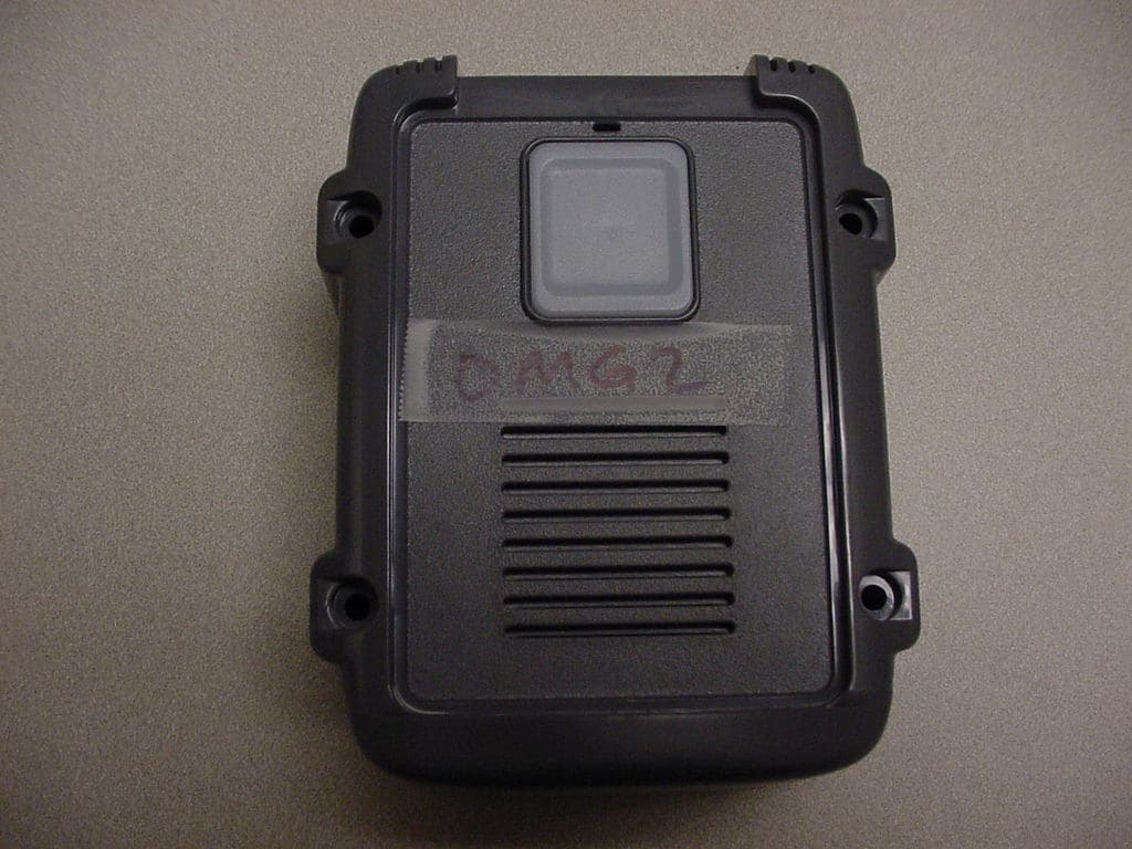
JLFOMG1
Mar 12, 2008Gate Access System
Equipment Class
DXX - Part 15 Low Power Communication Device Transmitter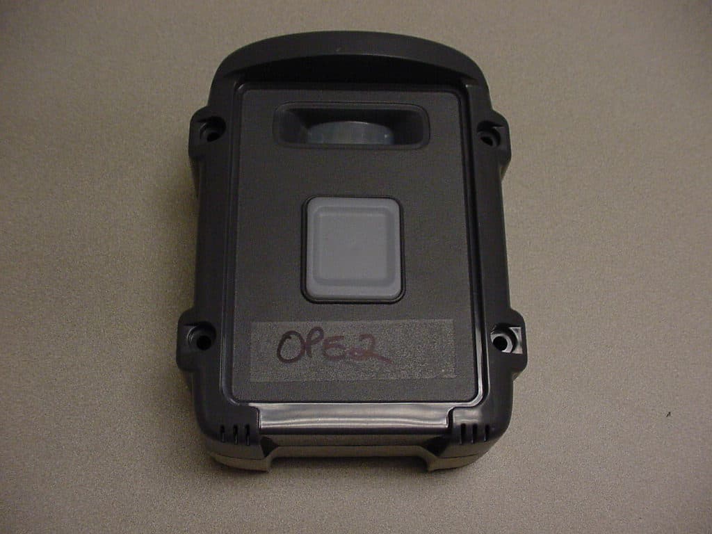
JLFPTE2
Mar 12, 2008Push to Exit
Equipment Class
DSC - Part 15 Security/Remote Control Transmitter
JLFKPD1
Jan 02, 2008Wireless Keypad Interface
Equipment Class
DXX - Part 15 Low Power Communication Device Transmitter