JLFPIR1Remote Control Device
Chamberlain Wireless Products Inc.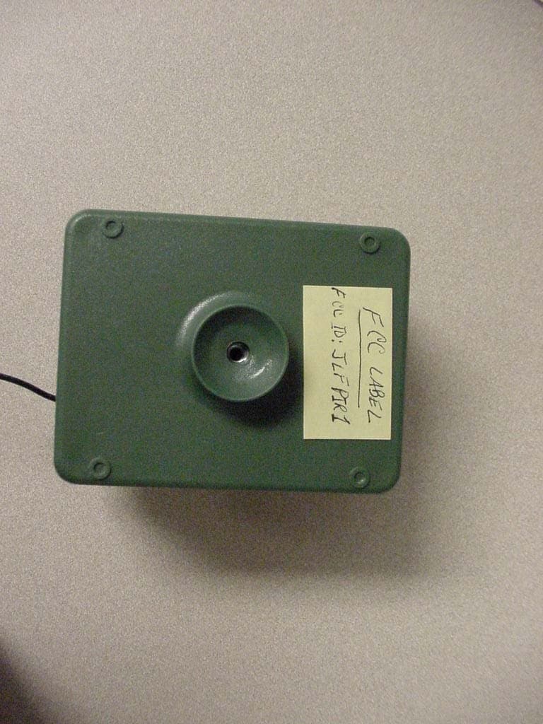
Click to zoom
Application Details
- Equipment Class
- DSC - Part 15 Security/Remote Control Transmitter
- Date of Grant
- Mar 31, 2008
- Application Purpose
- Original Equipment
- Date of Application
- Mar 31, 2008
- Equipment Note
- Remote Control Device
- Frequency Range
- 315.00000000 - 315.00000000
- Country
- United States
Documents & Files
Document Text
Text extracted from the exhibit documents filed with the FCC. Open a document above to read the original.
Users Manual
Carton Inventory Overview The Wireless Pedestrian & Vehicle Sensor is a Passive Infra-Red sensor that detects movement of people and vehicles, while allowing small animals to pass through undetected. Each PIR Motion Sensor has its own unique ID, for a secure radio link. Base Station (not provided) can learn the signals of up to four PIR Motion Sensors. The Base Station will give a single beep for the first Sensor that it learns, a double beep for the second, and so forth. Additionally, multiple Base Stations can work with the same PIR Motion Sensor to sound in different places. PIR Motion Sensor Assembly & Test Step 1 Attach PIR Motion Sensor box to mounting plate with large silver screw. Tighten screw until PIR Motion Sensor stays in place when repositioned. Model PIR2300R Wireless Pedestrian & Vehicle Sensor Passive Infra-Red (PIR) Motion Sensor 1 Swivel Bushing Mounting Plate Sun/Rain Shield ® PIR Sensor Antenna Switch Settings Step 2 Install 4 AA Alkaline batteries (not provided). (Lithium batteries recommended for colder environments.) LED light will flash. Switch #1 Switch #2 Test Button Switch #1:. Switch #2: ON OFF 1 2 OFFLow Sensitivity ONHigh Sensitivity (Default) OFF15' Detection Range ON30' Detection Range (Default) NOTE:To avoid unwanted detection of small animals move Switch #2 to OFF. 2 Step 5 Programming PIR Motion Sensor to Base Station Test PIR Motion Sensor by waving hand in front of sensor. Test light should flash. Secure cover with the smallest screws. Step 3 Insert battery pack facing away from circuit board and attach cover. NOTE:Ensure the batteries do not touch the circuit board and the antenna and battery wires are not pinched. Step 4 B Within 5 seconds, wave hand in front of PIR Motion Sensor. Test light will illuminate and Base Station will buzz. - - A B AEnsure Base Station and PIR Motion Sensor are in close proximity to each other. Press and release learn button on Base Station. Buzzer will sound. Step 6 PIR Motion Sensor Installation Mount PIR Motion Sensor horizontally on solid surface a few feet off the ground and within 1200' of Base Station (rotate sensor to access screw holes). Unit should be able to swivel as needed. Attach sun/rain shield. NOTE:Keep PIR Motion Sensor antenna away from metal objects. Do not mount PIR Motion Sensor in direct sunlight, near moving tree branches, or in lthe path of a sprinkler system. Troubleshooting The PIR Motion Sensor lights up, but the Base Station does not respond. The PIR Motion Sensor must be programmed to Base Station (See Step 5). Ensure Base Station is on and is not muted. If the green power light is not lit or is flashing, press the Mute Button on the top of the Base Station to wake it up. If the green power is illuminated, look at the two small white Base Station switches next to the Learn Button. The #1 Dip Switch should be down, towards the circuit board. If it is up, the Base Station has been muted. If the Base Station signals when you press the Learn Button, it is not muted. PIR Motion Sensor is detecting motion only part of the time. To detect cars, it is best to mount PIR Motion Sensor at height of car’s motor and have it between ten and twenty feet from the road. Swivel sensor as needed. The Alert is giving false alarms. Check for moving tree branches or insects in sensor window. PIR sensor can also be triggered by light shining directly in sensor window, such as reflected sunlight, or motion in front of a light source. It is possible that condensation has built up on the sensor. Wipe condensation from PIR Motion Sensor with cotton swab. Let it sit inside for a few hours, open to the air, without the batteries and it should correct itself. Check Sensor Switches on PIR Motion Sensor. See Switch Settings. 3 Base Station beeps every ten minutes. The battery in the Base Station is low. Replace with 9-Volt battery or operate it using AC Adapter. The Alert is not getting expected transmission range. Keep both antennas vertical and keep PIR Motion Sensor antenna away from trees and metal objects. Ensure Base Station is in clearest possible sight of the PIR Motion Sensor. The less objects between the devices, the longer the range. Base Station is not very loud. An accessory such as a bell, buzzer, or light can be attached to the relay switch. The relay switch can handle up to 120 AC volts at 10 amps. The accessory device will need a separate power supply. The accessories can be purchased at any electronics store. NOTE:The manufacturer is not responsible for any radio or TV interference caused by unauthorized modifications to this equipment. Changes or modifications not expressly approved by the manufacturer could void the user’s authority to operate the equipment. 3' - 5' 10' - 20' Vehicle Alert Installation: For cars, the best mounting position is about 4' high, between 10-20' back, and angled to see the back of car after passing the sensor. © 2007, The Chamberlain Group Inc. 114A3508All Rights Reserved FOR TECHNICAL SUPPORT DIAL OUR TOLL FREE NUMBER: 1-800-528-9131 www.chamberlain-DIY.com NOTICE: To comply with FCC and or Industry Canada rules (IC), adjustment or modifications of this receiver and/or transmitter are prohibited, except for changing the code setting or replacing the battery. THERE ARE NO OTHER USER SERVICEABLE PARTS. Tested to Comply with FCC Standards FOR HOME OR OFFICE USE. Operation is subject to the following two conditions: (1) this device may not cause harmful interference, and (2) this device must accept any interference received, including interference that may cause undesired operation.
Cover Letter(s)
FCC ID: JLFPIR1 Request for Confidentiality In accordance with 47 C.F.R. Section 0.459, we, Chamberlain Group, Inc., hereby request confidentiality for the block diagram, schematic and product description presented for certification. In support of the Request for Confidentiality, the following is stated: Enclosed within this application is technical information which we deem to be trade secrets and proprietary. If made public, the information might be used to our disadvantage. To assist in assuring that we receive the full value of our product and protect its competitive posture, we respectfully request this grant of confidentiality. Barbara Kelkhoff Manager of Regulatory Affairs Chamberlain Group, Inc. 845 Larch Ave. Elmhurst, IL. 60126
ID Label/Location Info
FCC ID tag for PIR-2 Location: Rear of the housing. PIR-2 TRANSMITTER FCCID:JLFPIR1 This device complies with FCC part 15 standards. This device may not cause harmful interference to other devices. This device must accept interference, including such which may cause unintended operation. Made In USA
Test Report
Engineering Test Report No. 0801243-01 Measurement of RF Interference from a Model PIR Transmitter For : The Chamberlain Group 845 Larch Ave. Elmhurst, IL 60126 P.O. No. : 857707 Date Tested : March 21 and 25, 2008 Test Personnel : Mark E. Longinotti Specification : FCC Part 15, Subpart C Industry Canada RSS-210 Industry Canada RSS-GEN Test Report By : Mark E. Longinotti Approved By : Raymond J. Klouda Registered Professional Engineer of Illinois - 44894 Elite Electronic Engineering Inc. 1516 Centre Circle Downers Grove, IL 60515 Tel : (630) 495-9770 Fax: (630) 495-9785 www.elitetest.com Engineering Test Report No. 0801243-01 THIS REPORT SHALL NOT BE REPRODUCED, EXCEPT IN FULL, WITHOUT THE WRITTEN APPROVAL OF ELITE ELECTRONIC ENGINEERING INCORPORATED. Page 2 of 19 TABLE OF CONTENTS PARAGRAPH DESCRIPTION OF CONTENTS PAGE NO. 1 INTRODUCTION ............................................................................................................................................... 4 1.1 Scope of Tests .......................................................................................................................................... 4 1.2 Purpose .................................................................................................................................................... 4 1.3 Deviations, Additions and Exclusions....................................................................................................... 4 1.4 EMC Laboratory Identification .................................................................................................................. 4 1.5 Laboratory Conditions .............................................................................................................................. 4 2 APPLICABLE DOCUMENTS ............................................................................................................................ 4 3 TEST ITEM SET-UP AND OPERATION .......................................................................................................... 4 3.1 General Description .................................................................................................................................. 4 3.1.1 Power Input .......................................................................................................................................... 5 3.1.2 Peripheral Equipment........................................................................................................................... 5 3.1.3 Interconnect Cables ............................................................................................................................. 5 3.1.4 Grounding............................................................................................................................................. 5 3.2 Operational Mode ..................................................................................................................................... 5 3.3 Test Item Modifications............................................................................................................................. 5 4 TEST FACILITY AND TEST INSTRUMENTATION..........................................................................................5 4.1 Shielded Enclosure................................................................................................................................... 5 4.2 Test Instrumentation ................................................................................................................................. 5 4.3 Calibration Traceability ............................................................................................................................. 5 4.4 Measurement Uncertainty ........................................................................................................................ 5 5 TEST PROCEDURES ....................................................................................................................................... 6 5.1 Powerline Conducted Emissions .............................................................................................................. 6 5.2 Duty Cycle Factor Measurements ............................................................................................................ 6 5.2.1 Procedures ........................................................................................................................................... 6 5.2.2 Results.................................................................................................................................................. 6 5.3 Radiated Measurements .......................................................................................................................... 6 5.3.1 Requirements ....................................................................................................................................... 6 5.3.2 Procedures ........................................................................................................................................... 6 5.3.3 Results.................................................................................................................................................. 7 5.4 Occupied Bandwidth Measurements........................................................................................................ 7 5.4.1 Requirement ......................................................................................................................................... 7 5.4.2 Procedures ........................................................................................................................................... 7 5.4.3 Results.................................................................................................................................................. 7 6 OTHER TEST CONDITIONS ..............................................…
Text truncated - open the document above for the full version.
Test Setup Photos
Engineering Test Report No. 0801243-01 Page 11 of 19 Figure 2 Test Set-up for Radiated Emissions – Horizontal Polarization Test Set-up for Radiated Emissions – Vertical Polarization
Contact Information
Applicant
Barbara Kelkhoff(Manager of Regulatory Affairs)
Technical Contact
Chamberlain GroupHank Sieradzki
[email protected]6309936564
845 Larch Ave · Elmhurst, Illinois · United States
Test Firm
Elite Electronic Engineering Inc.Kevin Halpin
Technical Specifications
| # | Rule Parts | Frequency Range | Power Output |
|---|---|---|---|
| 1 | 15.231 | 315 MHz - 315 MHz | - |
Other Applications from Chamberlain Wireless Products Inc.
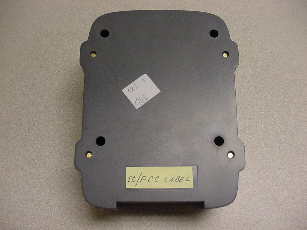
JLFOPB2
Mar 12, 20083 Button Push to Exit
Equipment Class
DXX - Part 15 Low Power Communication Device Transmitter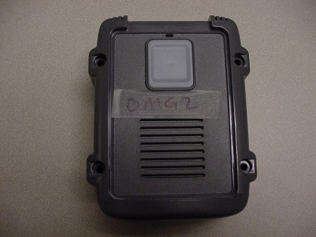
JLFOMG1
Mar 12, 2008Gate Access System
Equipment Class
DXX - Part 15 Low Power Communication Device Transmitter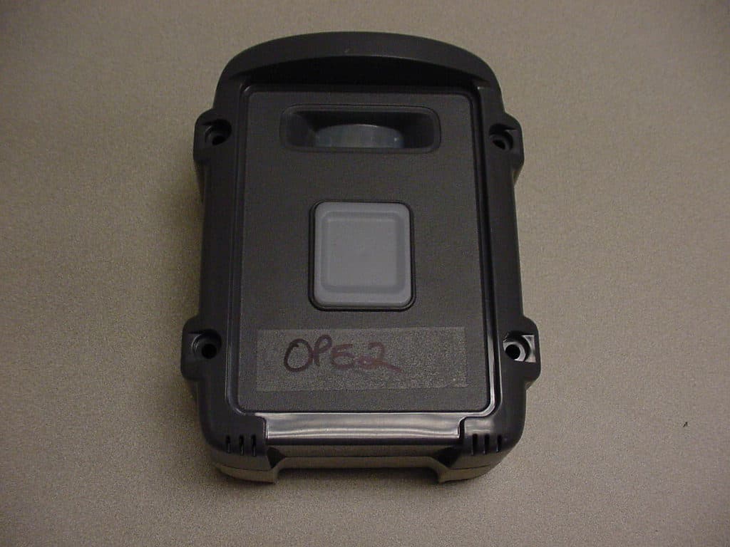
JLFPTE2
Mar 12, 2008Push to Exit
Equipment Class
DSC - Part 15 Security/Remote Control Transmitter
JLFKPD1
Jan 02, 2008Wireless Keypad Interface
Equipment Class
DXX - Part 15 Low Power Communication Device Transmitter
JLFTRX2
Jan 01, 2008Wireless Intercom
Equipment Class
DXX - Part 15 Low Power Communication Device Transmitter