JLFPTE2Push to Exit
Chamberlain Wireless Products Inc.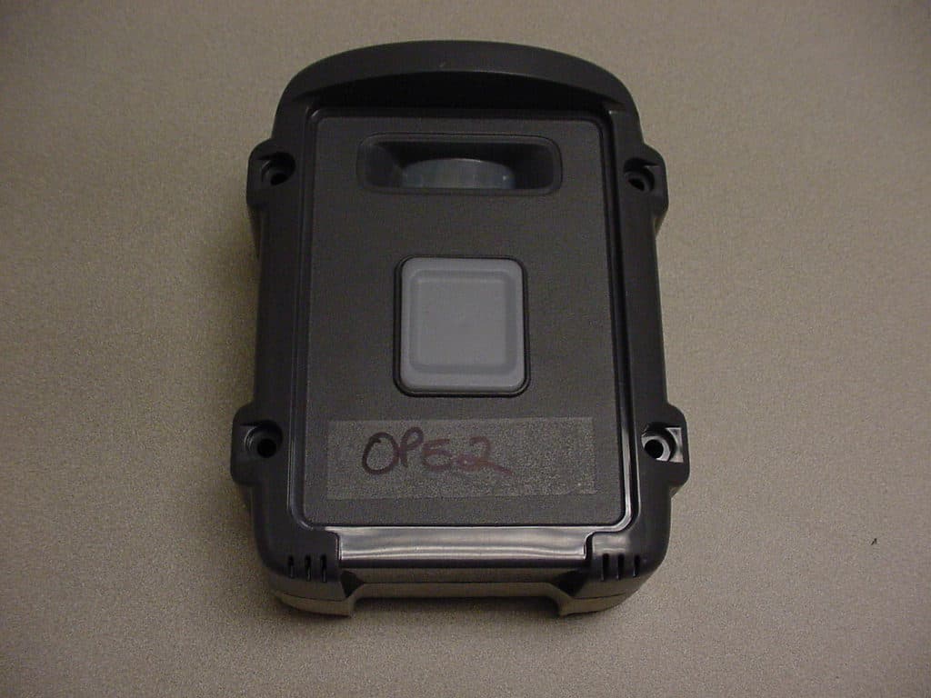
Click to zoom
Application Details
- Equipment Class
- DSC - Part 15 Security/Remote Control Transmitter
- Date of Grant
- Mar 12, 2008
- Application Purpose
- Original Equipment
- Date of Application
- Mar 12, 2008
- Equipment Note
- Push to Exit
- Frequency Range
- 315.00000000 - 315.00000000
- Country
- United States
Documents & Files
Document Text
Text extracted from the exhibit documents filed with the FCC. Open a document above to read the original.
Users Manual
- 4 - Made With Pride In the USA. A manufacturer’s full One Year Warranty covers this product. - 1 - Oracle (TM) Push To Exit Thank you for purchasing one of the Oracle Push To Exit products. This product has been designed and manufactured in the USA, utilizing the highest quality standards available. One year limited WARRANTY International Electronics Inc. (IEI) warrants this product to be free of defects in materials and workmanship, for one year. For a period of ONE YEAR following purchase, IEI will repair or replace the product free of charge, including parts , labor, return shipping to you, and handling. After the initial one year of operation, the limite d lifetime warranty will cover parts, labor, and return shipping to you, with a minimal handling cha rge specific to the product, as listed below: PUSH TO EXIT: $20.00 If you have installation or operation questions or are in need of warranty service, please contact our Product Support department by email at [email protected] or call 360- 254-1564 Tuesday-Friday 7-5 Pacific Time. If the is sue i s not resolvable, a manufacturer’s warranty repair order may be issued. To have the pr oduct(s) sent for warranty service. A Return Authorization number will be issued for warr anty service, which must be put on the outside of the package, to be received an d handled properly. Packages for warranty service may be sent to the following address. Packages with no RA# may not be accepted. IEI 5913C NE 127th AVE, Suite 800 Vancouver, WA 98682 Please include a note describing the problem that y ou are having a nd a copy of your original sales receipt (within the first year). If the warra nty service is outside the first year, please include a check made out to IEI, based on the list of handling fees, shown above. Please note that you may need to send multiple units for w arranty service, testing, and upgrading, though only the applicable fee for handling the fai led unit(s) will be charged. Please allow 2-4 weeks for service and return shipp ing. If an EXPEDITED repair/replacement is requested, a 100% surcharge app lies. In this case, please write EXPEDITED after th e RA number. IEI will attempt to return expedited repair orders within one week, except during holidays. All repairs or replacements are at the discretion o f the Manufacturer. This warranty excludes items that have been abused, altered, incorrectly i nstalled, or repaired by an unauthorized person. Changes or modifications not expressly appr oved by the Manufacturer could void the user’s authority to operate the equipment. The manu facturer is not responsible for any radio or TV interference caused by unauthorized modificat ions to this equipment. Such modifications could void the user’s authority to op erate the equipment. This warranty is limited to the product only. No consequential damag es are covered. This device complies with part 15 of the FCC Rules. Operation is subject to the following two conditions: (1) This device may not cause harmful i nterference, and (2) this device must accept any interference received, including interfe rence that may cause undesired operation. International Electronics, Inc. FCC ID: JLFPTE1 Country Of Origin: USA • Completely Wireless • Up to 1000 Foot Range • Algorithmically Secure • UV Hardened ABS Enclosure • Button Light When Motion Detected • Audible Confirmation • Pedestal or Surface Mount • Invisible to Lightning OPE2 Patents Pending 7/25/2007 DSW 1 DSW 2 OFF OFF ON OFF OFF ON ON ON Step 1 & 2 must occur within 5 seconds of each othe r. ACTIVATING A PUSH TO EXIT TO AN EXISTING MINIGAP NETWORK Step 1 & 2 must occur within 5 seconds of each othe r. PUSH TO EXIT - 2 - - 3 - GCU DIPSWITCH SETTINGS GCU #1 CLEARING THE MEMORY Step 1 & 2 must occur within 5 seconds of each othe r. ACTIVATING A PUSH TO EXIT TO A GCU Step 1 & 2 must occur within 5 seconds of each other. ACTIVATING A PUSH TO EXIT TO AN EXISTING KEYPAD NET WORK #2 #3#4 USING THE PUSH TO EXIT ACTIVATING A PUSH TO EXIT TO AN EXISTING GAP NETWOR K The Push Is Exit is designed to be activated into a n existing Gate Access Network. Install 4 ‘AA’ batteries into the Push To Exit. Li thium are preferred in cold climates. 1. Press the LEARN button on a Push To Exit. 2. On the Gate Access Panel (GAP), Enter the Master Pin Number (for example): Followed by: The Push To Exit will respond with a beep indicatin g a successful activation. 1 2 3 4 0 5 NOTE: If the GCU has already been activated to a Ga te Access Panel (GAP), Keypad, or MiniGAP, then the Push To Exit should al so be activated to the GAP, Keypad, or MiniGAP 1. Press the LEARN button on the GCU. 2. Press the LEARN button on the Push To Exit. The Push To Exit will respond with a beep indicatin g a successful activation. The Push Is Exit is factory set to control GCU #1. Simply press the button to exit. Hold down the learn button until you hear the beep. 1. Press the LEARN button on the Push To Exit. 2. Press the LEARN button on the MiniGAP. The Push To Exit will respond with a beep indicatin g a successful activation. 1. Press the LEARN button on the Push To Exit. 2. Press the LEARN button on the Keypad. The Push To Exit will respond with a beep indicatin g a successful activation. OPE2 Patents Pending 7/25/2007
Cover Letter(s)
FCC ID: JLFPTE2 Request for Confidentiality In accordance with 47 C.F.R. Section 0.459, we, Chamberlain Group, Inc., hereby request confidentiality for the block diagram, schematic and product description presented for certification. In support of the Request for Confidentiality, the following is stated: Enclosed within this application is technical information which we deem to be trade secrets and proprietary. If made public, the information might be used to our disadvantage. To assist in assuring that we receive the full value of our product and protect its competitive posture, we respectfully request this grant of confidentiality. Barbara Kelkhoff Manager of Regulatory Affairs Chamberlain Group, Inc. 845 Larch Ave. Elmhurst, IL. 60126
ID Label/Location Info
This device complies with part 15 of the FCC Rules. Operation is subject to the following two conditions: (1)This device may not cause harmful interference, and (2) this device must accept any interference received, including interference that may cause undesired operation. FCC ID: JLFPTE2
Test Report
Underwriters Laboratories Inc. 1285 Walt Whitman Rd. Melville, NY 11747 www.ul.com/emc (631) 271-6200 Job Number: 772545 File Number: MC3181 Date: 08 Oct. 2007 Model: FCC ID: OPE2 JLFPTE2 Electromagnetic Compatibility Test Report For Chamberlain Group Inc. Copyright © 2007 Underwriters Laboratories Inc. Underwriters Laboratories Inc. authorizes the above-named company to reproduce this Report provided it is reproduced in its entirety. Underwriters Laboratories Inc. A not-for-profit organization dedicated 1285 Walt Whitman Rd. Melville, NY 11747 Tel: (631) 271-6200 Fax: (631)439-6095 to public safety and committed to quality service for over 100 years Job Number: 772545 File Number: MC3181 Page 2 of 37 Model Number: OPE2 Client Name: Chamberlain Group Inc. FCC ID: JLFPTE2 Test Report Details Tests Performed By: Underwriters Laboratories Inc. 1285 Walt Whitman Rd. Melville, NY 11747 Tests Performed For: Chamberlain Group Inc. 845 Larch Av Elmhurst, IL 60126 Applicant Contact: Hank Sieradzki Title: Not Provided Phone: (630) 993-6564 Fax: Not Provided E-mail: [email protected] Test Report Date: 08 Oct. 2007 Product Type: Wireless PushToExit Product standards FCC Part 15, Subpart C, 15.231 Model Number: OPE2 Sample Serial Number: Not Provided EUT Category: Periodic Low Power Transmitter Testing Start Date: 24 Sep 2007 Date Testing Complete: 05 Oct 2007 Overall Results: Compliant Underwriters Laboratories Inc. reports apply only to the specific samples tested under stated test conditions. All samples tested were in good operating condition throughout the entire test program. It is the manufacturer's responsibility to assure that additional production units of this model are manufactured with identical electrical and mechanical components. Underwriters Laboratories Inc. shall have no liability for any deductions, inferences or generalizations drawn by the client or others from Underwriters Laboratories Inc. issued reports. This report shall not be used to claim, constitute or imply product certification, approval, or endorsement by NVLAP, A2LA, or any agency of the US government. This report may contain test results that are not covered by the NVLAP or A2LA accreditation. The scope of accreditation is limited to the specific tests that are listed on the NVLAP and/or A2LA websites referenced at the end of this report. Underwriters Laboratories Inc. 1285 Walt Whitman Rd. Melville, New York 11747 USA Tel.: 631 271-6200 Fax: 631 439-6095 Rev. No 1.0 EMC Report 2007 Job Number: 772545 File Number: MC3181 Page 3 of 37 Model Number: OPE2 Client Name: Chamberlain Group Inc. FCC ID: JLFPTE2 Report Directory 1.0 G E N E R A L - Product Description..................................................................................................................4 1.1 Equipment Description...................................................................................................................................4 1.2 Equipment Marking Plate...............................................................................................................................4 1.3 Device Configuration During Test..................................................................................................................5 1.3.1 Equipment Used During Test:....................................................................................................................5 1.3.2 Input/Output Ports:.....................................................................................................................................5 1.3.3 EUT Internal Operating Frequencies:........................................................................................................6 1.3.4 Power Interface:.........................................................................................................................................6 1.4 Block Diagram:...............................................................................................................................................7 1.5 EUT Configurations........................................................................................................................................8 1.6 EUT Operation Modes....................................................................................................................................8 2.0 Summary............................................................................................................................................................9 2.1 Deviations from standard test methods..........................................................................................................9 2.2 Device Modifications Necessary for Compliance...........................................................................................9 2.3 Reference Standards.................................................................................................................................. 10 2.4 Results Summary........................................................................................................................................10 3.0 Calibration of Equipment Used for Measurement...........................................................................................12 4.0 EMISSIONS TEST RESULTS.........................................................................................................................12 4.1 Test Conditions and Results – OCCUPIED BANDWIDTH.........................................................................13 4.2 Test Conditions and Results – CEASE OPERATION.................................................................................18 4.3 Test Conditions and Results – PULSE TRAIN...........................................................................................21 4.4 Test Conditions and Results – RADIATED EMISSIONS............................................................................24 4.5 Fundamental Frequenc…
Text truncated - open the document above for the full version.
Test Setup Photos
Job Number: 772545 File Number: MC3181 Page 14 of 37 Model Number: OPE2 Client Name: Chamberlain Group Inc. FCC ID: JLFPTE2 Figure 1 Test Setup for Occupied Bandwidth Underwriters Laboratories Inc. 1285 Walt Whitman Rd. Melville, New York 11747 USA Tel.: 631 271-6200 Fax: 631 439-6095 Rev. No 1.0 EMC Report 2007 Job Number: 772545 File Number: MC3181 Page 19 of 37 Model Number: OPE2 Client Name: Chamberlain Group Inc. FCC ID: JLFPTE2 Figure 4 Test Setup for Cease Operation Underwriters Laboratories Inc. 1285 Walt Whitman Rd. Melville, New York 11747 USA Tel.: 631 271-6200 Fax: 631 439-6095 Rev. No 1.0 EMC Report 2007 Job Number: 772545 File Number: MC3181 Page 22 of 37 Model Number: OPE2 Client Name: Chamberlain Group Inc. FCC ID: JLFPTE2 Figure 6 Test Setup for Pulse Train Underwriters Laboratories Inc. 1285 Walt Whitman Rd. Melville, New York 11747 USA Tel.: 631 271-6200 Fax: 631 439-6095 Rev. No 1.0 EMC Report 2007 Job Number: 772545 File Number: MC3181 Page 27 of 37 Model Number: OPE2 Client Name: Chamberlain Group Inc. FCC ID: JLFPTE2 Figure 8 Test setup for Radiated Emissions (30MHz-1GHz) Figure 9 Test setup for Radiated Emissions (1-5GHz) Underwriters Laboratories Inc. 1285 Walt Whitman Rd. Melville, New York 11747 USA Tel.: 631 271-6200 Fax: 631 439-6095 Rev. No 1.0 EMC Report 2007
Contact Information
Applicant
Barbara Kelkhoff(Manager of Regulatory Affairs)
Technical Contact
The Chamberlain Group IncHank Sieradzki
[email protected]630-993-6564
845 Larch Ave. · Elmhurst, Illinois · United States
Non-Technical Contact
The Chamberlain Group IncHank Sieradzki
[email protected]630-993-6564
Test Firm
UL LLCBob Delisi
Technical Specifications
| # | Rule Parts | Frequency Range | Power Output |
|---|---|---|---|
| 1 | 15.231 | 315 MHz - 315 MHz | - |
Other Applications from Chamberlain Wireless Products Inc.
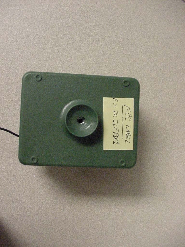
JLFPIR1
Mar 31, 2008Remote Control Device
Equipment Class
DSC - Part 15 Security/Remote Control Transmitter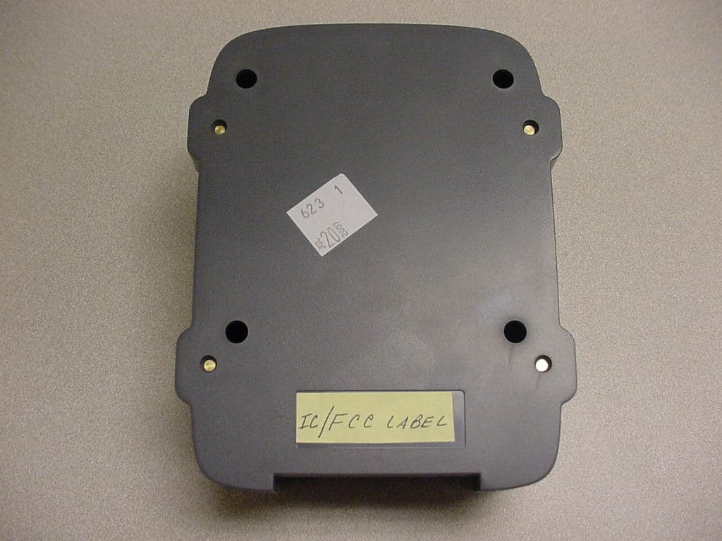
JLFOPB2
Mar 12, 20083 Button Push to Exit
Equipment Class
DXX - Part 15 Low Power Communication Device Transmitter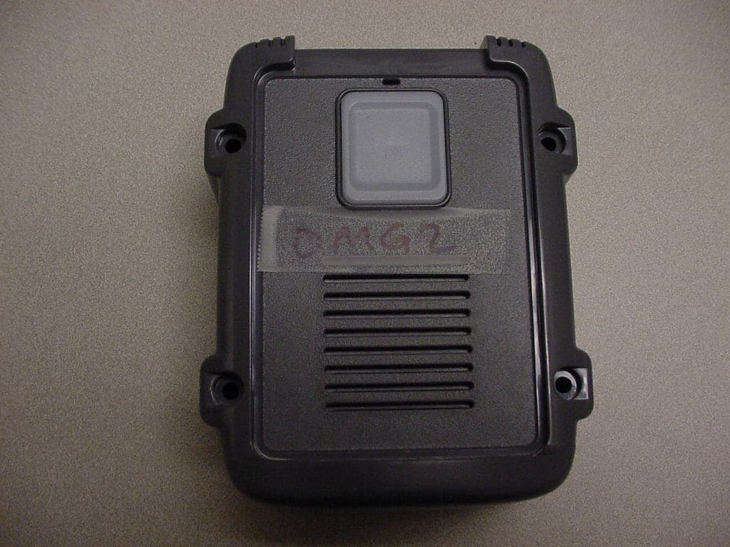
JLFOMG1
Mar 12, 2008Gate Access System
Equipment Class
DXX - Part 15 Low Power Communication Device Transmitter
JLFKPD1
Jan 02, 2008Wireless Keypad Interface
Equipment Class
DXX - Part 15 Low Power Communication Device Transmitter
JLFTRX2
Jan 01, 2008Wireless Intercom
Equipment Class
DXX - Part 15 Low Power Communication Device Transmitter