JLFOMG1Gate Access System
Chamberlain Wireless Products Inc.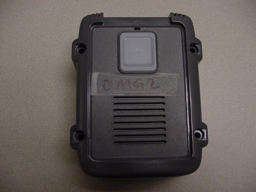
Click to zoom
Application Details
- Equipment Class
- DXX - Part 15 Low Power Communication Device Transmitter
- Date of Grant
- Mar 12, 2008
- Application Purpose
- Original Equipment
- Date of Application
- Mar 12, 2008
- Equipment Note
- Gate Access System
- Frequency Range
- 903.00000000 - 926.00000000
- Country
- United States
Documents & Files
Document Text
Text extracted from the exhibit documents filed with the FCC. Open a document above to read the original.
Users Manual
MOUN TING TEMPLATE (Use this templa te as a guide for mounting screw placement) NOTE: The manu facturer is not re sponsible f o r an y r a dio or TV int e r f erence caused b y unauthorized mod i fications to this equi pment. Chang e s o r mo dificatio n s no t expressly approved by the pa rty re spo n sibl e fo r co m p l i a nce co uld void the user’s a u thor ity to oper a t e the equipme n t. If you have in stal l a ti on or op e r ation quest ion s , p l ease see ab ove , or c h ec k out the exp a n d ed FA Q at the man u fac t ur er ’s web p a g e a t ww w. re p o rt e r wi r e l e ss.c o m . Y o u can r e ceive f r e e technical assistanc e or w a rr anty se r v ic e, by email at te ch s u pp@n w link .co m o r call 888.679.799 4 x 290 Tuesday-Fr i d ay 8-5 PST Warranty : This pro duct is wa rranted to be fr ee of de fects for the pe ri od of One Ye ar from the date of pu rch a se. Th e w a rran t y covers parts, labor, an d retu rn sh ippin g to you , bu t n o t all accessories . I E I will repair or replace an y d e fe ctive product at our discretion. W a rrant y does not cover misuse or dama g e othe r than due to normal oper a ting conditions. I f y ou n eed to send the s y stem to I E I fo r r e pa i r, contact I E I for a R e turn Authoriz ation num ber via e m a il: t e c h supp@n w li nk.c o m . Packa g es without a Return Authoriz ation number will b e rej e ct ed. MiniGA P2 Syst em Fe atur es : • Easy to mo u n t o n any surface o r i n a n y lo cat i on • Weather R e s i stant Design • Use Out s id e t h e F r ont do o r or f o r a si d e doo r • Wir e l e ss Gat e Ac cess C o n t rol • Up to Tw o Ye ar battery lif e • S e c u re di gi ta l c o n n e c tio n • Unlim i t e d nu mber o f un it s can op erat e o n a pro p e r ty, wi tho u t i n terfe r i n g wi th other Intercom net w orks. T h an k y ou for p u rc has i ng the Or acle MiniGAP2. This pro d u c t ha s bee n de si g n ed an d m a nufact ure d i n t h e USA, u t ili zing th e hi gh es t q u a l i t y s t and a rd s av ail a bl e . Mo d e l OMG2 102406 P a t e nt s p e nd i n g The Ora c le™ Mini GAP 2 unit can be your primary door an d gate access system or used as an a c cessory to a Gate Access Panel (GAP). For pri v acy, your Ora c le system forms an exclusive netw ork , a n d r e spon d s only to other units in your netw ork. (Paten t Pen d in g) Since this MiniGAP2 A c cess and Intercom system requires no connecti on to wall power, it is perfect for remote locations . Please read the instructi o n s carefully. Made W i t h Pr id e In t h e U S A . T h i s pr o duc t i s co ver e d by a m a nufac turer’ s f u ll One Year W a rranty . FCC STATEMENT T h is devic e c o m p lies w i t h F CC par t 15 r u les . It m a y n o t c aus e har m f ul inter f er enc e with oth e r de vic e s , and m u s t ac c ept in ter f er enc e f r o m other d e v i c e s . S etting Up the MiniGAP2 Installation Make sure that the CA LL button is in easy reach of a visit o r. To mo unt the M i niGA P2 with four screws, use the include d mo unting tem p late (see Back Page) as a guide for screw placement. Tighten the top two screws halfway. Place the back of the MiniG A P2 on th e two t o p screws and tig h ten. Put the other two screws in the bottom h o les and t i ghten. Note: Do not assemble the front of the unit until it has been activated. Use the double -sided mounting tape to mount the Mini GAP2 on a meta l, glass, or o t her sm o o t h surface where yo u wo uldn’t want to use screws. Note: Fo r be st re sul t s, cl e a n b o th sur f a c es tha t the doubl e -sided mounting tape will be in contact with, using the in cluded a l co ho l wipe. Peel the pro t ective paper o f f o f the mounting tape a n d firmly press it onto the back of the MiniGAP2. Press firmly on the back of the tape to push out a n y trapped air bubbles. Wh en ready to do s o , peel the red protective paper fro m the mountin g tape and fir m ly press the Mini GAP2 on t o the surface that you wish to mou n t it on. Note: Do not assemble the front of the unit until it has been activated. Batteries Place four A A A l ka line batteries in the battery pack. T h e batteries should last up to two years wit h average use. Note: I f u s e d i n l o c a t i o n t h a t w i l l b e b e l o w -10 ° C (20 ° F) Lithium bat t eries are r e comme n d e d . A Do ubl e -beep every ten m i nute s indicates low batteries. Add PHOTO HERE Activati ng Oracle Accessory Units The MiniGAP2 is shipped with Dip Switch #1 in t h e U P p o s i t i o n m a k i n g i t a n “ A c t i v e ” u n i t . I f the MiniGA P2 is going to be the “Passive” unit, Dip Switc h #2 will need to be in the DOWN positi on and then follo w t h e directions listed under “M ulti-GA P Mo de”. Activating a Gat e Control Unit (GCU) (only if this MiniG A P2 is the “Acti v e ” unit) Press and ho ld down the GC U l e arn button for 1 second. Within 20 seconds press and ho ld do wn the M i niGAP2 learn butto n fo r 10 seco nds o r until the M i niGA P2 beeps in response as it activates the GCU. Activating Oracle Inte rc oms (only if this MiniG A P2 is the “Acti v e ” unit) Press and release the LEA R N button on the Intercom. Withi n 20 seconds, press and hold do wn the M i ni GA P2 learn but t o n fo r o n e second . The Intercom will beep in response when it joins the system network . NO TE: F o r a W a ll F l ush moun t I n ter c om, hold down both buttons of the I n ter c om for 3 seconds (until the cha nnel lig hts start fast -fl ashi n g ) t h en rel e ase t h em . Asse mbli ng t h e M i niG A P2 Put the two h a lves of the In tercom body together and place the 4 black screws in the top and bottom holes on the front of the unit and tighten with the hex key provided. The Interco m is ready to use. Using the MiniGAP When a visitor presses th e C A LL button, Interco m units will give an att e ntio n-getting beep and if un answered, co ntinue to beep f o r 4 0 s e c o n d s . D u r i n g t h i s t i m e , Intercom…
Text truncated - open the document above for the full version.
Cover Letter(s)
FCC ID: JLFOMG1 Request for Confidentiality In accordance with 47 C.F.R. Section 0.459, we, Chamberlain Group, Inc., hereby request confidentiality for the block diagram, schematic and product description presented for certification. In support of the Request for Confidentiality, the following is stated: Enclosed within this application is technical information which we deem to be trade secrets and proprietary. If made public, the information might be used to our disadvantage. To assist in assuring that we receive the full value of our product and protect its competitive posture, we respectfully request this grant of confidentiality. Barbara Kelkhoff Manager of Regulatory Affairs Chamberlain Group, Inc. 845 Larch Ave. Elmhurst, IL. 60126
ID Label/Location Info
This device complies with part 15 of the FCC Rules. Operation is subject to the following two conditions: (1)This device may not cause harmful interference, and (2) this device must accept any interference received, including interference that may cause undesired operation. FCC ID: JLFOMG1
Test Report
Flom Test Labs 3356 N. San Marcos Place, Suite 107 Chandler, Arizona 85225-7176 p0690002, d0780025 (866) 311-3268 phone, (480) 926-3598 fax Date: August 22, 2007 Federal Communications Commission Via: Electronic Filing Attention: Authorization & Evaluation Division Applicant: International Electronics Inc. Equipment: MiniGap II FCC ID: JLFOMG2 FCC Rules: 15.249 Gentlemen: On behalf of the Applicant, enclosed please find Application Form 731, Engineering Test Report and all pertinent documentation, the whole for approval of the referenced equipment as shown. We trust the same is in order. Should you need any further information, kindly contact the writer who is authorized to act as agent. Sincerely yours, Hoosamuddin S. Bandukwala, Lab Director enclosure(s) cc: Applicant HSB/mdw Flom Test Labs 3356 N. San Marcos Place, Suite 107 Chandler, Arizona 85225-7176 p0690002, d0780025 (866) 311-3268 phone, (480) 926-3598 fax List Of Exhibits (FCC Certification (Transmitters) - Revised 9/28/98) Applicant: International Electronics Inc. FCC ID: JLFOMG2 By Applicant: 1. Letter Of Authorization 2. Identification Drawings Id Label Location Info Attestation Statement(s) Location of Compliance Statement 3. Documentation: 2.1033(B) (3) User Manual(s) (4) Operational Description (5) Block Diagram (5) Schematic Diagram (7) External Photographs Internal Photographs Parts List Active Devices By F.T.L. Inc. A. Testimonial & Statement of Certification B. Statement of Qualifications Flom Test Labs 3356 N. San Marcos Place, Suite 107 Chandler, Arizona 85225-7176 p0690002, d0780025 (866) 311-3268 phone, (480) 926-3598 fax Transmitter Certification of FCC ID: JLFOMG2 Model: MiniGap II to Federal Communications Commission Rule Part(s) 15.249 Date Of Report: August 22, 2007 On the Behalf of the Applicant: International Electronics Inc. 5913-C NE 127th Ave, Suite 800 Vancouver, WA 98682 Attention of: Shary Nassimi, President (360) 241-9090 email: [email protected] Supervised By: Hoosamuddin S. Bandukwala, Lab Director Flom Test Labs 3356 N. San Marcos Place, Suite 107 Chandler, Arizona 85225-7176 p0690002, d0780025 (866) 311-3268 phone, (480) 926-3598 fax The applicant has been cautioned as to the following: 15.21 Information to User. The users manual or instruction manual for an intentional radiator shall caution the user that changes or modifications not expressly approved by the party responsible for compliance could void the user's authority to operate the equipment. 15.27(a) Special Accessories. Equipment marketed to a consumer must be capable of complying with the necessary regulations in the configuration in which the equipment is marketed. Where special accessories, such as shielded cables and/or special connectors are required to enable an unintentional or intentional radiator to comply with the emission limits in this part, the equipment must be marketed with, i.e. shipped and sold with, those special accessories. However, in lieu of shipping or packaging the special accessories with the unintentional or intentional radiator, the responsible party may employ other methods of ensuring that the special accessories are provided to the consumer, without additional charge. Information detailing any alternative method used to supply the special accessories for a grant of equipment authorization or retained in the verification records, as appropriate. The party responsible for the equipment, as detailed in § 2.909 of this chapter, shall ensure that these special accessories are provided with the equipment. The instruction manual for such devices shall include appropriate instructions on the first page of text concerned with the installation of the device that these special accessories must be used with the device. It is the responsibility of the user to use the needed special accessories supplied with the equipment. Flom Test Labs 3356 N. San Marcos Place, Suite 107 Chandler, Arizona 85225-7176 p0690002, d0780025 (866) 311-3268 phone, (480) 926-3598 fax Testimonial And Statement Of Certification This is to certify that: 1. That the application was prepared either by, or under the direct supervision of, the undersigned. 2. That the technical data supplied with the application was taken under my direction and supervision. 3. That the data was obtained on representative units, randomly selected. 4. That, to the best of my knowledge and belief, the facts set forth in the application and accompanying technical data are true and correct. Certifying Engineer: Hoosamuddin S. Bandukwala, Lab Director Flom Test Labs 3356 N. San Marcos Place, Suite 107 Chandler, Arizona 85225-7176 p0690002, d0780025 (866) 311-3268 phone, (480) 926-3598 fax Table Of Contents Rule Description Page Test Report 1 2.1033(c) General Information Required 2 . Standard Test Conditions and Engineering Practices 4 Test Results Summary 5 15.249. Field Strength of Fundamental 6 15.249(d) Field Strength of Harmonics 6 15.249(c), Radiated Spurious Emissions 7 . Test Equipment Utilized 9 Flom Test Labs 3356 N. San Marcos Place, Suite 107 Page 1 of 9 Chandler, Arizona 85225-7176 p0690002, d0780025 (866) 311-3268 phone, (480) 926-3598 fax Required information per ISO 17025-2005, paragraph 5.10: a) Test Report b) Laboratory: (FCC: 31040/SIT) (Canada: IC 2044) Flom Test Lab, Inc. 3356 N. San Marcos Place, Suite 107 Chandler, AZ 85225 c) Report Number: d0780025 d) Client: International Electronics Inc. e) Identification: MiniGap II Description: Transmitter f) EUT Condition: Not required unless specified in individual tests. g) Report Date: August 22, 2007 EUT Received: h, j, k): As indicated in individual tests. i) Sampling method: No sampling procedure used. l) Uncertainty: In accordance with FTL internal quality manual. m) Supervised by: Hoosamuddin S. Bandukwala, Lab Director n) Results: The results presented in this report relate only to the item tested. o) Reproduction: This report must not be reproduced, except in full, without written permission from this lab…
Text truncated - open the document above for the full version.
Contact Information
Applicant
Barbara Kelkhoff(Manager of Regulatory Affairs)
Technical Contact
The Chamberlain Group Inc.Hank Sieradzki
[email protected]630-993-6564
845 Larch Ave · Elmhurst · United States
Non-Technical Contact
The Chamberlain Group Inc.Hank Sieradzki
[email protected]630-993-6564
Test Firm
Compliance Testing, LLCMichael Schafer
Technical Specifications
| # | Rule Parts | Frequency Range | Power Output |
|---|---|---|---|
| 1 | 15C | 903 MHz - 926 MHz | - |
Other Applications from Chamberlain Wireless Products Inc.
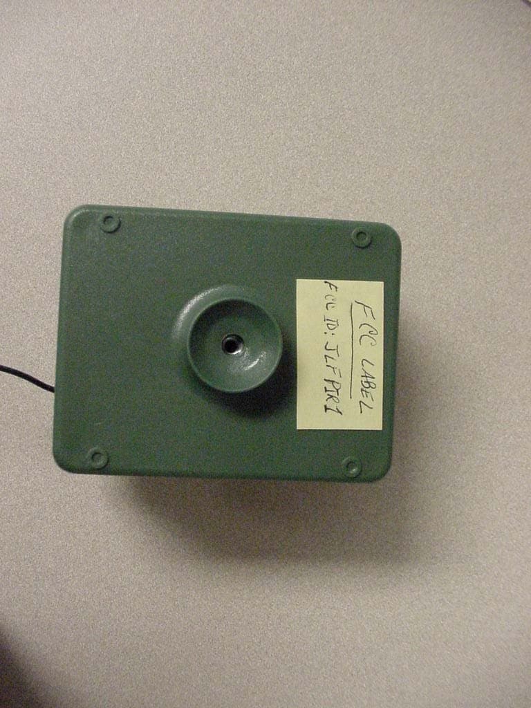
JLFPIR1
Mar 31, 2008Remote Control Device
Equipment Class
DSC - Part 15 Security/Remote Control Transmitter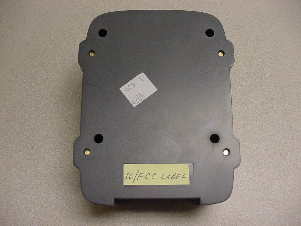
JLFOPB2
Mar 12, 20083 Button Push to Exit
Equipment Class
DXX - Part 15 Low Power Communication Device Transmitter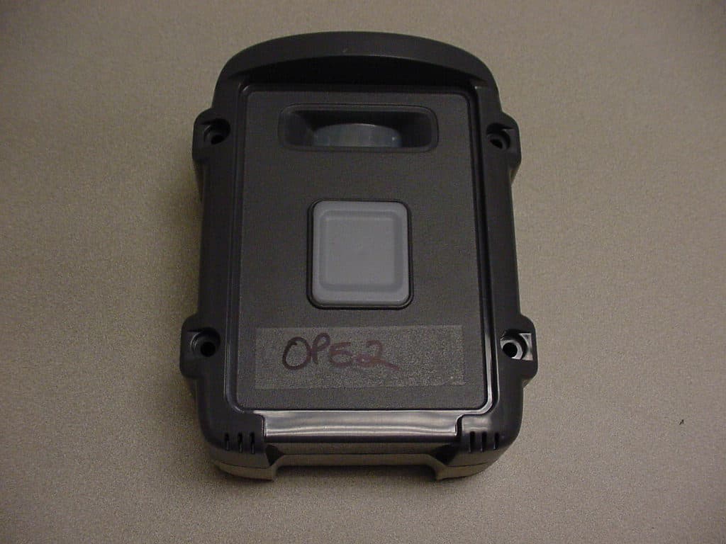
JLFPTE2
Mar 12, 2008Push to Exit
Equipment Class
DSC - Part 15 Security/Remote Control Transmitter
JLFKPD1
Jan 02, 2008Wireless Keypad Interface
Equipment Class
DXX - Part 15 Low Power Communication Device Transmitter
JLFTRX2
Jan 01, 2008Wireless Intercom
Equipment Class
DXX - Part 15 Low Power Communication Device Transmitter