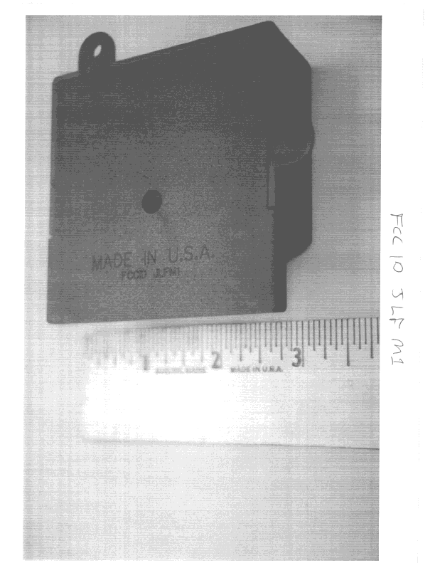
Click to zoom
Application Details
- Equipment Class
- CRR - Superregenerative Receiver
- Date of Grant
- Dec 12, 1999
- Application Purpose
- Original Equipment
- Date of Application
- Aug 23, 1999
- Frequency Range
- 310.00000000 - 310.00000000
- Country
- United States
Documents & Files
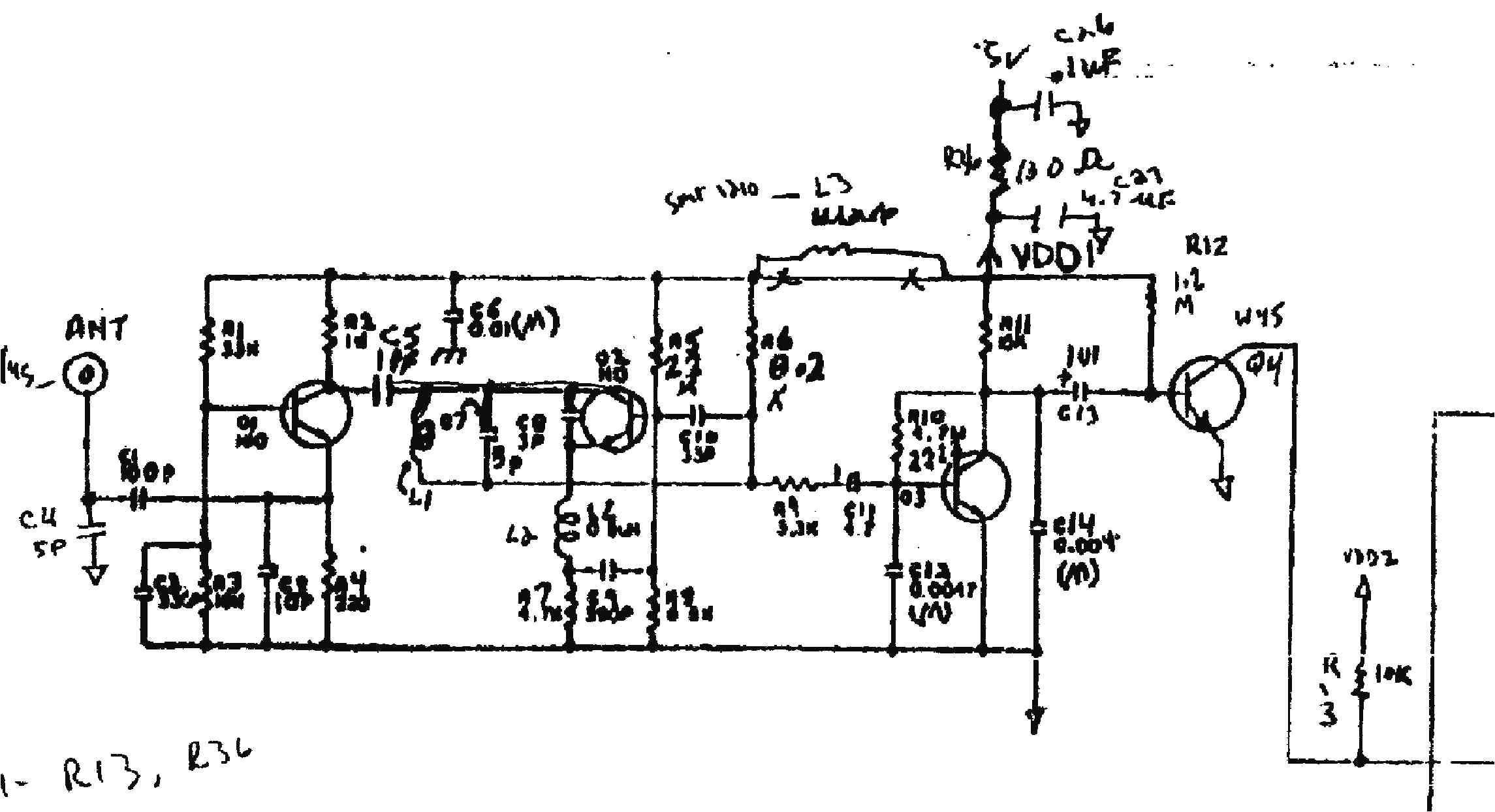
Document Text
Text extracted from the exhibit documents filed with the FCC. Open a document above to read the original.
Test Report
GM99059f 1 of 9 FCC EMC TEST REPORT FOR THE INTERNATIONAL ELECTRONICS, INC. FCCID JLFM1 CAR ALARM RECEIVER Prepared for: International Electronics, Inc. 12609 NE 95th Street Suite 106-B Vancouver, WA 98682 USA Submitted by: Green Mountain Electromagnetics, Inc. GME (802)388-3390 Fax: (802)388-6279 Email: [email protected] 219 Blake Roy Road • Middlebury, VT 05753 Copyright: November 24, 1999 GM99059f 2 of 9 This report may not be reproduced, except in full, without the written approval of GME. GM99059f 3 of 9 International Electronics, Inc. FCC EMC Testing At Green Mountain Electromagnetics, Inc. Middlebury, Vermont Unit: SideKik 3000 Mini Receiver Tested: November 24, 1999 (revised) Received: 11/23/99 I. Applicable Standards: The unit described in this report was measured for verification of compliance with the FCC Unintentional Radiator EMC standard, 47 CFR: Part 15, Subpart C. Measurement procedures were in accordance with ANSI C63.4, "Methods of Measurement of Radio-Noise Emissions from Low-Voltage Electrical and Electronic Equipment in the Range of 9 kHz to 40 GHz (1992)." II. Units Tested: The International Electronics, Inc. SideKik 3000 (SideKik) receiver is part of the SideKik automobile alarm and accessory control system. The SideKik consists of a plastic case containing the receiver electronics and a permanently attached external antenna. There is no provision for connecting the SideKik to an AC power source; consequently, a conducted emissions test was not performed. The table below describes the unit that was subjected to measurements determining compliance with applicable EMC standards: ProductManufacturerModelFCC ID Automobile Alarm/Accessory Control System International Electronics SideKik 3000 Receiver JLFM1 GM99059f 4 of 9 III. Equipment and Cable Configuration: GME received the unit in satisfactory condition for testing, however the manufacturer is responsible for ensuring that the equipment under test (EUT) represents the product line. The EUT was arranged on a turntable as in the block diagram below. This EUT configuration produced the maximum radiated emissions. The EUT was subjected to final emissions tests while connected to all loads and operating in a continuous mode. 3" 4" Turntable SideKik Receiver Wire Antenna The temperature, humidity, and atmospheric pressure during unit testing were 21 ̊C, 50% RH and 100.1 kPa for radiated emissions. A signal generator and transmitting antenna tuned to the fundamental were used to provide a coherence signal to the receiver IV. Measuring Equipment: The table below describes the instrumentation used at Green Mountain Electromagnetics, Inc. (GME) to perform this testing: UnitManufacturerModelSerial #Last Cal.Next Cal. Spectrum Analyzer Hewlett- Packard 85923624A006318/9/998/9/00 GM99059f 5 of 9 Broadband Amplifier Mini-CircuitsZJL-3GD0216992/20/992/20/00 PlotterHewlett- Packard 74402539A09149n/an/a Broadband E- field Antenna Antenna Research Associates LPB-2513/A11259/25/999/25/00 TurntableAntenna Research Associates ART-10001004n/an/a Antenna Mast Antenna Research Associates AS-6201004n/an/a Signal Generator Hewlett- Packard E4421BUS382201958/9/998/9/00 V. Unit of Measurement: Measurements of radiated electric fields were made in units of dB referenced to 1 microvolt per meter (dBuV/m). Average data is not required as the unit is compliant with average limits in peak detection mode. Fields and deviations in the results table were corrected for the appropriate antenna factor, cable loss, amplifier gain and measurement distance X (per 47 CFR, C15.31). The following equations were employed: (1) Field (dBuV/m) = Measured Value (dBuV) + Antenna Factor (dB) + Cable Loss (dB) - Amplifier Gain (dB). (2) Pass/Fail Deviation (dB) = Field (dBuV/m) - Limit (dBuV/m) - 20 log(X/3 meters). Sample calculation at 30 MHz: 32.0 dBuV/m field = 32.5 dBuV measured + 19 dB/m AF + 0.5 dB cable loss - 20.0 dB amp. -8.0 dB deviation = 32.0 dBuV/m field - 40.0 dBuV/m limit - 20 log(3/3) dB distance. Uncertainty: The combined uncertainty for GME radiated emissions measurements is: u(y) = 1.946. VI. Measurement Location: GM99059f 6 of 9 The GME laboratory and Open Area Test Site (OATS) are located at 219 Blake Roy Road, Middlebury, VT. The OATS is a 3-meter site complete with antenna positioner, ground plane and motorized turntable. The OATS is constructed in accordance with ANSI C63.7-1992 and complies with the requirements for radiated emissions testing in ANSI C63.4-1992 and CISPR 16-1993. The electromagnetic laboratory is constructed in accordance with CE immunity standards and ANSI C63.4-1992 (conducted emissions). GME is internationally accredited by the American Association for Laboratory Accreditation (A2LA) and meets the quality requirements in EN 45001-1989 and ISO/IEC Guide 25-1990, "General Requirements for the Competence of Calibration and Testing Laboratories." VII. Measurement Procedures: 1. Radiated Emissions in accordance with FCC Part 15.209 & 15.231. Frequency range: 30 MHz to 88 MHz Limit: 40 dBuV @ 3 meters Frequency range: 88 MHz to 216 MHz Limit: 43.5 dBuV @ 3 meters Frequency range: 216 MHz to 960 MHz Limit: 46 dBuV @ 3 meters Frequency range: 960 MHz to 3.1 GHz Limit: 54 dBuV @ 3 meters a.Set up instrumentation at open area test site. i. Mount EUT on turntable and broadband antenna on antenna positioner. ii. Record temperature, humidity and atmospheric pressure. iii. Measurement distance is 3 meters and antenna scan height is varied from 1 to 4 meters. b.Verify spectrum analyzer and antenna operation. i. Spectrum analyzer is connected to antenna. ii. Broadband amplifier is inserted between antenna and analyzer to ensure analyzer noise threshold is at least 6 dB below specification limit. c.Set up, power and operate EUT as described in section III. d.Perform preliminary evaluation of equipment in the near field. i. Vary antenna height, antenna polarization, and antenna orientation to EUT. ii. Repeat step d.i. while evaluating elec…
Text truncated - open the document above for the full version.
Contact Information
Applicant
Barbara Kelkhoff(Manager of Regulatory Affairs)
Test Firm
Green Mountain ElectromagneticsKyle Kowalczyk
Technical Specifications
| # | Rule Parts | Frequency Range | Power Output | Tolerance |
|---|---|---|---|---|
| 1 | 15B | 310 MHz - 310 MHz | - | % |
Other Applications from Chamberlain Wireless Products Inc.
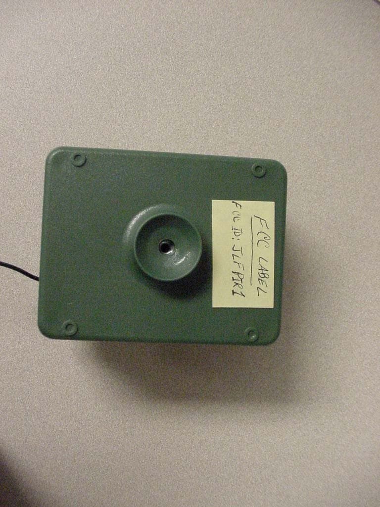
JLFPIR1
Mar 31, 2008Remote Control Device
Equipment Class
DSC - Part 15 Security/Remote Control Transmitter
JLFOPB2
Mar 12, 20083 Button Push to Exit
Equipment Class
DXX - Part 15 Low Power Communication Device Transmitter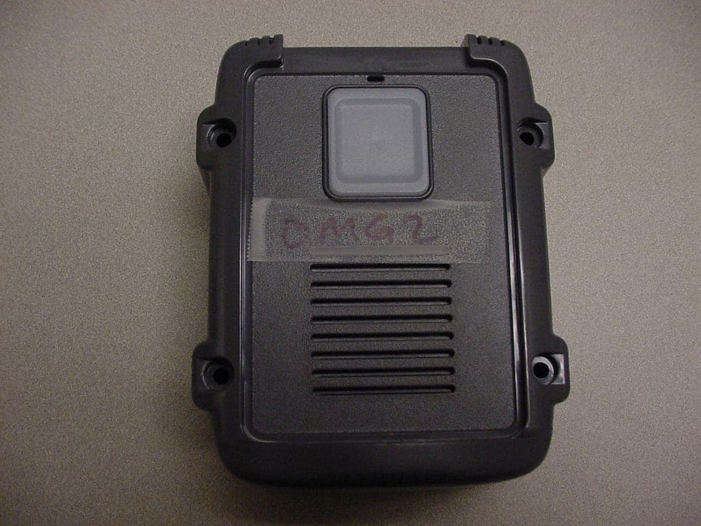
JLFOMG1
Mar 12, 2008Gate Access System
Equipment Class
DXX - Part 15 Low Power Communication Device Transmitter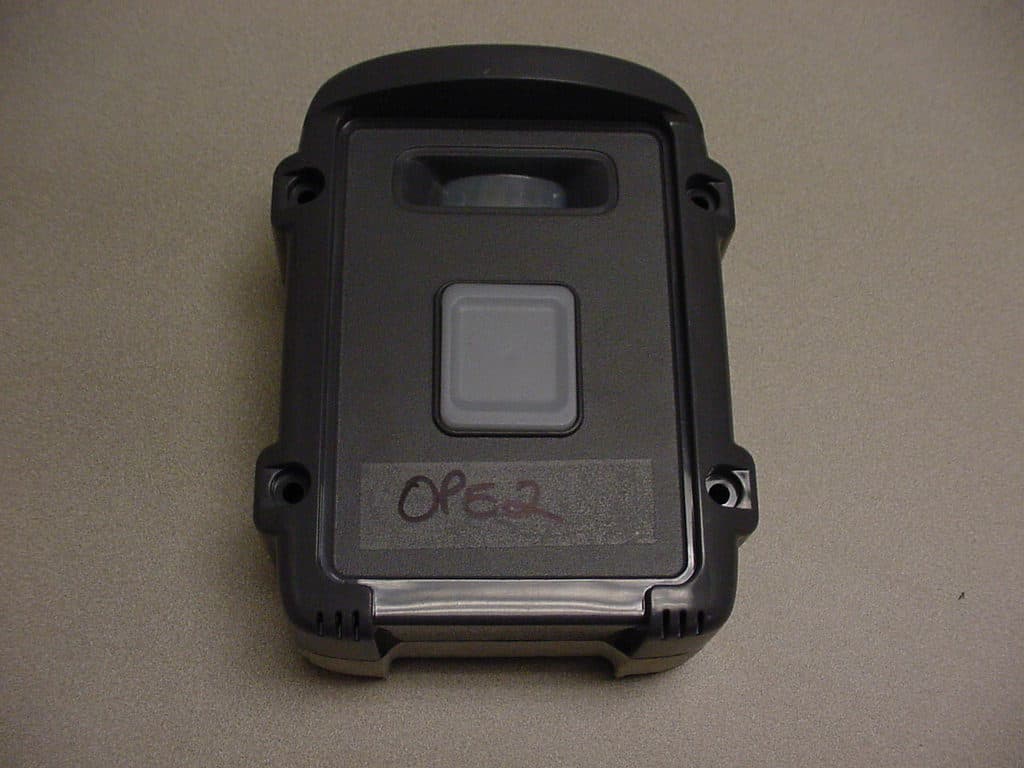
JLFPTE2
Mar 12, 2008Push to Exit
Equipment Class
DSC - Part 15 Security/Remote Control Transmitter
JLFKPD1
Jan 02, 2008Wireless Keypad Interface
Equipment Class
DXX - Part 15 Low Power Communication Device Transmitter