JLFTRX2Wireless Intercom
Chamberlain Wireless Products Inc.
Click to zoom
Application Details
- Equipment Class
- DXX - Part 15 Low Power Communication Device Transmitter
- Date of Grant
- Jan 01, 2008
- Application Purpose
- Original Equipment
- Date of Application
- Jan 01, 2008
- Equipment Note
- Wireless Intercom
- Frequency Range
- 902.00000000 - 928.00000000
- Country
- United States
Documents & Files
Document Text
Text extracted from the exhibit documents filed with the FCC. Open a document above to read the original.
Users Manual
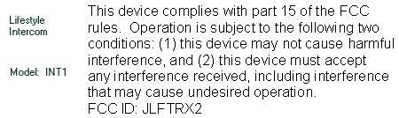
(this page intenti onally left blank) Part 15.21 Changes or modi fications not expressly approved by the party responsible for compliance could void the user's authority to operate the equipment. NOTE The manufacture is not responsible for any radi o or TV interference caused by unauthorized modifications to this equipment. Such modifications could void the user's authority to operate the equipment. International Electronics, Inc. FCC ID: JLF TRX2 Country Of Origin: USA Multiple Uses Include... • Garage or Workshop • Between Offices • Back Porch or Pool • Camping or Hunting • Temporary Work Locations • Nursery or Patient Monitor • Home Office • Motor Home or Guest Room • Network wide conference mode Made With Pride In the USA. This product is covered by a manufacturer’s full One Year Warranty. FCC STATEMENT This device complies with FCC part 15 rules. It may not cause harmful interference with other devices, and must accept interfer ence from other devices. FCC ID: JLFTRX2 Thank you for purchasing the Lifestyle Wirefree Intercom. This product has been designed and manufactured in the USA, utilizing the highest quality standards available. Model 06/16/05 Patents pending With the Lifestyle Wirefree Intercom, you can talk up to 1000 feet, completely wire free with a 900 MHz secure digital radio link. For privacy, your intercoms form an exclusive network, and respond only to other intercoms in your network. (Patent Pending) Even conversations within your network are secure, as intercoms automatically pair up, blocking all other intercoms from listening in. Additional features include: hands-free operation, baby monitoring with adjustable sensitivity, and non-secure conferencing mode. Please read the instructions carefully. TM INTERCOM QUICK SETUP GUIDE 1) Remove the battery door fr om the bottom of each unit and place four fresh AA Alkaline batteries in the battery pack. The batteries are installed, the channel lights will begin to flash in sequence. 2) To create an Intercom Network, stand the antennas up, then Press the LEARN button for 1 second on each intercom. Note: LEARN buttons must be pressed within ten seconds of each other on the first two units. The units will beep as they join the Network. Additional In tercoms may be added to the network at any time by pressing the LEARN button on one of the networked units and on the new unit. 3) Press and release the TALK button on an Intercom unit to verify that the network is complete. Using the Intercom To talk, hold down the TALK button. All intercom units in your network will receive the signal. When somebody responds by holding down the TALK button on a different intercom unit, a secure channel is created and other units will not hear the signal, making your conversation secure. Channel Selection The default setting for the intercom is Paging Mode, with all four Channel lights flashing in sequence). Pressing the CHANNEL button will set an intercom unit to one of four secure channels. While on a channel, you can only be heard by other units set to the same channel or in paging mode. Adjusting the speaker volume Press the VOLUME button up or down to adjust loudness of unit. Turning the intercom On or Off An intercom may be turned off by holding down the VOLUME button down for five seconds. To turn it back on, press any button. Volume Active/ Monitor Power Light Channel Power Monitoring Mode (Patent Pending) Press monitor to place the intercom in monitor mode, making it voice activated. To adjust sensitivity, press the VOLUME button to cycle through the three sensitivity settings, with three beeps being the most sensitive. To talk to this unit from another intercom on the same channel, press the TALK button, even while hearing audio from the unit in monitoring mode. Voice Activation Mode (VOX) When in VOX mode, you may answer a call by simply speaking loudly. After a brief delay, your intercom will begin to send audio, and will wait for you to finish speaking. To place the unit in VOX mode , slide dipswitch #1, UP (by the LEARN button). Note: the caller may interrupt you at any time by pressing TALK on their intercom. Conference Mode To put an intercom unit in Conference mode, slide dipswitch #2 UP. This will allow any number of units to join a conversation, not just two. Batteries With average use, the batteries will last up to one year, or four months in monitoring mode. A double beep every ten minutes will alert you that the batteries are getting low. If desired, the Intercom may also be powered by a 12-volt DC transformer (commonly available) in most department stores). In this case, both the power and channel lights will remain on constantly. Troubleshooting and Frequently Asked Questions My intercom does nothin g. What should I do? If there are no lights illuminated, make sure four fresh AA alkaline batteries are all installed correctly. The CHANNEL lights should flash. If you are using the optional 12-volt transformer, make sure it is plugged in. The POWER and CHANNEL lights should be continuously on. If not, try another outlet. If the units have power but do not communic ate, they may need to form a network. Press the LEARN button on each unit that needs to form a network and they will beep in response. You may need to clear their memory and re-teach them (see Removing from a Network, below). If the units do not have the same channel light flashing, press the CHANNEL button until both units are on the same channel or in Paging mode, with all channel lights illuminated. How do I Remove an Intercom from a Network? Press and hold the Learn button, for fifteen seconds. It will beep when it has cleared its memory and you can re-teach it to a new intercom. If an intercom signals, while the Learn button is depressed, the procedure will have to be repeated. Why is the intercom not getting the expected 1000 foot range? To assure best range, make sure that the intercom unit’s antenna is VERTICAL. Cell phones, cordless phones, or other radio de…
Text truncated - open the document above for the full version.
Cover Letter(s)
FCC ID: JLFTRX2 Request for Confidentiality In accordance with 47 C.F.R. Section 0.459, we, Chamberlain Group, Inc., hereby request confidentiality for the block diagram, schematic and product description presented for certification. In support of the Request for Confidentiality, the following is stated: Enclosed within this application is technical information which we deem to be trade secrets and proprietary. If made public, the information might be used to our disadvantage. To assist in assuring that we receive the full value of our product and protect its competitive posture, we respectfully request this grant of confidentiality. Barbara Kelkhoff Manager of Regulatory Affairs Chamberlain Group, Inc. 845 Larch Ave. Elmhurst, IL. 60126
Parts List/Tune Up Info
IntercomII Rev A Active Devices Item Part Type Designator(s) QTY Mfg Function 1 MMBT2222 Q3. Q5,Q6 3 ST Micro NPN transistor 2 3.6864 MHz Y1 1 Abracon crystal 3 ADF7020 U2 1 Analog 900 MHz transceiver 4 ATMEGA8 IC2 1 Atmel microcontroller 5 11.0592 MHz Y2 1 Abracon crystal 6 74HC164 IC8 1 Fairchild shift register 7 LMV932 IC6 1 National dual op amp 8 TPS76630D V1 1 TI 3.3V regulator 9 TS4871 IC5 1 ST Micro Audio amp 10 UPG2214 U1 1 CEL T/R switch 11 XE3005 IC3 1 Xemics Audio Codec 12 78M05 V2 1 National 5V regulator 13 BAT54 D4,D9 2 NXP diode 13 BAS316 D12 1 NXP diode
Test Report
Underwriters Laboratories Inc. 1285 Walt Whitman Rd. Melville, NY 11747 www.ul.com/emc (631) 271-6200 Job Number: 771347 File Number: MC3181 Date: 01 Nov 2007 Model: FCC ID: Intercom II JLFTRX2 Electromagnetic Compatibility Test Report For Chamberlain Group Inc. Copyright © 2007 Underwriters Laboratories Inc. Underwriters Laboratories Inc. authorizes the above-named company to reproduce this Report provided it is reproduced in its entirety. Underwriters Laboratories Inc. A not-for-profit organization dedicated 1285 Walt Whitman Rd. Melville, NY 11747 Tel: (631) 271-6200 Fax: (631)439-6095 to public safety and committed to quality service for over 100 years Job Number: 771347 File Number: MC3181 Page 2 of 83 Model Number: Intercom II Client Name: Chamberlain Group Inc. FCC ID: JLFTRX2 Test Report Details Tests Performed By: Underwriters Laboratories Inc. 1285 Walt Whitman Rd. Melville, NY 11747 Tests Performed For: Chamberlain Group Inc. 845 Larch Av Elmhurst, IL 60126 Applicant Contact: Hank Sieradzki Phone: (630) 993-6564 E-mail: [email protected] Test Report Date: 01 Nov 2007 Product Type: Wireless Intercom Product standards FCC Part 15, Subpart C, 15.207, 15.209, 15.215, 15.249 FCC Part 15, Subpart B, 15.107, 15.109 Model Number: Intercom II Sample Serial Number: Not Provided EUT Category: Low Power Transmitter Testing Start Date: 17 Sep 2007 Date Testing Complete: 01 Nov 2007 Overall Results: Compliant Underwriters Laboratories Inc. reports apply only to the specific samples tested under stated test conditions. All samples tested were in good operating condition throughout the entire test program. It is the manufacturer's responsibility to assure that additional production units of this model are manufactured with identical electrical and mechanical components. Underwriters Laboratories Inc. shall have no liability for any deductions, inferences or generalizations drawn by the client or others from Underwriters Laboratories Inc. issued reports. This report shall not be used to claim, constitute or imply product certification, approval, or endorsement by NVLAP, A2LA, or any agency of the US government. This report may contain test results that are not covered by the NVLAP or A2LA accreditation. The scope of accreditation is limited to the specific tests that are listed on the NVLAP and/or A2LA websites referenced at the end of this report. Underwriters Laboratories Inc. 1285 Walt Whitman Rd. Melville, New York 11747 USA Tel.: 631 271-6200 Fax: 631 439-6095 Rev. No 1.0 EMC Report 2007 Job Number: 771347 File Number: MC3181 Page 3 of 83 Model Number: Intercom II Client Name: Chamberlain Group Inc. FCC ID: JLFTRX2 Report Directory 1.0 G E N E R A L - Product Description..................................................................................................................4 1.1 Equipment Description...................................................................................................................................4 1.2 Equipment Marking Plate...............................................................................................................................4 1.3 Device Configuration During Test..................................................................................................................5 1.3.1 Equipment Used During Test:....................................................................................................................5 1.3.2 Input/Output Ports:.....................................................................................................................................5 1.3.3 EUT Internal Operating Frequencies:........................................................................................................6 1.3.4 Power Interface:.........................................................................................................................................6 1.4 Block Diagram:...............................................................................................................................................7 1.5 EUT Configurations........................................................................................................................................8 1.6 EUT Operation Modes....................................................................................................................................8 2.0 Summary............................................................................................................................................................9 2.1 Deviations from standard test methods..........................................................................................................9 2.2 Device Modifications Necessary for Compliance...........................................................................................9 2.3 Reference Standards.................................................................................................................................. 10 2.4 Results Summary........................................................................................................................................10 3.0 Calibration of Equipment Used for Measurement...........................................................................................11 4.0 EMISSIONS TEST RESULTS.........................................................................................................................11 4.1 Test Conditions and Results – MAINS TERMINAL – CONDUCTED EMISSIONS....................................12 4.2 Test Conditions and Results – OCCUPIED BANDWIDTH.........................................................................30 4.3 Test Conditions and Results – RADIATED EMISSIONS............................................................................36 Appendix A.........................................................................................................................................…
Text truncated - open the document above for the full version.
Test Setup Photos
Job Number: 771347 File Number: MC3181 Page 13 of 83 Model Number: Intercom II Client Name: Chamberlain Group Inc. FCC ID: JLFTRX2 Table 2 Conducted Emissions Test Equipment Test Equipment Used Description Manufacturer Model Identifier Conducted Emissions – GP 1 Spectrum Analyzer Agilent E7402A ME5B-123 LISN EMCO 3825/2R ME5-790 Switch Driver HP 11713A 44397 RF Switch Box UL 4 44404 Measurement Software UL Version 9.3 44736 Temp/Humidity/ Pressure Meter Cole Parmer 99760-00 43734 Figure 1 Test Setup for Conducted Emissions Underwriters Laboratories Inc. 1285 Walt Whitman Rd. Melville, New York 11747 USA Tel.: 631 271-6200 Fax: 631 439-6095 Rev. No 1.0 EMC Report 2007 Job Number: 771347 File Number: MC3181 Page 31 of 83 Model Number: Intercom II Client Name: Chamberlain Group Inc. FCC ID: JLFTRX2 Table 13 Occupied Bandwidth Test Equipment Test Equipment Used Description Manufacturer Model Identifier Spectrum Analyzer Advantest R3261C 5A229 Dipole Antenna EMCO 3121C 3359 Temp/Humidity/ Pressure Meter Cole Parmer 99760-00 4268 Measurement Software UL Version 9.3 44740 Figure 10 Test Setup for Occupied Bandwidth Underwriters Laboratories Inc. 1285 Walt Whitman Rd. Melville, New York 11747 USA Tel.: 631 271-6200 Fax: 631 439-6095 Rev. No 1.0 EMC Report 2007 Job Number: 771347 File Number: MC3181 Page 39 of 83 Model Number: Intercom II Client Name: Chamberlain Group Inc. FCC ID: JLFTRX2 Figure 20 Test setup for Radiated Emissions (Front and Rear Views – 9kHz-30MHz Transmit Mode) Figure 21 Test setup for Radiated Emissions (Front and Rear Views – 30-1000MHz Transmit or Receive Mode) Underwriters Laboratories Inc. 1285 Walt Whitman Rd. Melville, New York 11747 USA Tel.: 631 271-6200 Fax: 631 439-6095 Rev. No 1.0 EMC Report 2007 Job Number: 771347 File Number: MC3181 Page 40 of 83 Model Number: Intercom II Client Name: Chamberlain Group Inc. FCC ID: JLFTRX2 Figure 22 Test setup for Radiated Emissions (Front and Rear Views –1-10GHz Transmit Mode) Figure 23 Test setup for Radiated Emissions (Front and Rear Views – 1-5GHz Receive Mode ) Underwriters Laboratories Inc. 1285 Walt Whitman Rd. Melville, New York 11747 USA Tel.: 631 271-6200 Fax: 631 439-6095 Rev. No 1.0 EMC Report 2007 Job Number: 771347 File Number: MC3181 Page 41 of 83 Model Number: Intercom II Client Name: Chamberlain Group Inc. FCC ID: JLFTRX2 Figure 24 Test setup for Radiated Emissions (Front and Rear Views –1-10GHz Wall Mount Orientation Transmit Mode) Underwriters Laboratories Inc. 1285 Walt Whitman Rd. Melville, New York 11747 USA Tel.: 631 271-6200 Fax: 631 439-6095 Rev. No 1.0 EMC Report 2007
Contact Information
Applicant
Barbara Kelkhoff(Manager of Regulatory Affairs)
Technical Contact
The Chamberlain Group, Inc.Hank Sieradzki
[email protected]630-993-6564
845 Larch Ave. · Elmhurst, Illinois · United States
Non-Technical Contact
The Chamberlain Group, Inc.Hank Sieradzki
[email protected]630-993-6564
Test Firm
UL LLCBob Delisi
Technical Specifications
| # | Rule Parts | Frequency Range | Power Output |
|---|---|---|---|
| 1 | 15C | 902 MHz - 928 MHz | - |
Other Applications from Chamberlain Wireless Products Inc.
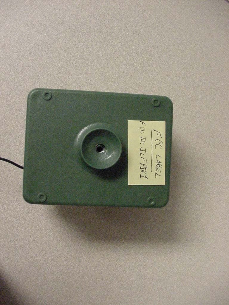
JLFPIR1
Mar 31, 2008Remote Control Device
Equipment Class
DSC - Part 15 Security/Remote Control Transmitter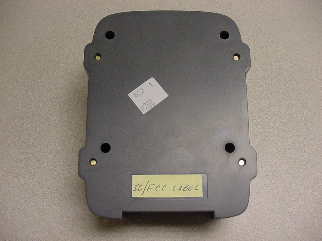
JLFOPB2
Mar 12, 20083 Button Push to Exit
Equipment Class
DXX - Part 15 Low Power Communication Device Transmitter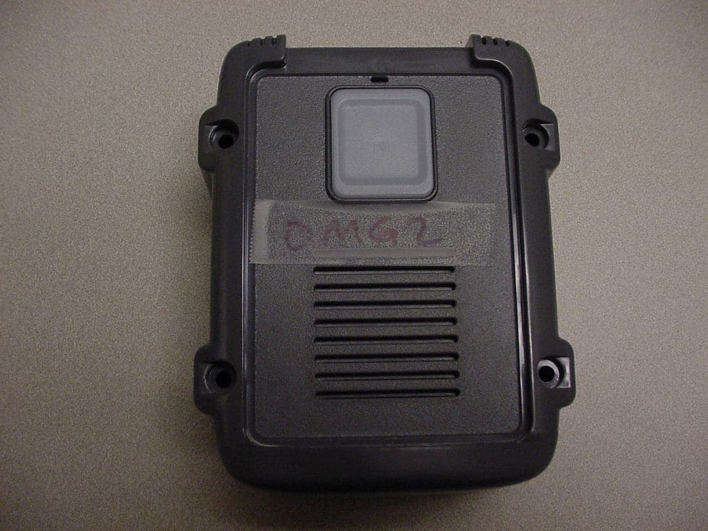
JLFOMG1
Mar 12, 2008Gate Access System
Equipment Class
DXX - Part 15 Low Power Communication Device Transmitter
JLFPTE2
Mar 12, 2008Push to Exit
Equipment Class
DSC - Part 15 Security/Remote Control Transmitter
JLFKPD1
Jan 02, 2008Wireless Keypad Interface
Equipment Class
DXX - Part 15 Low Power Communication Device Transmitter