JLFPIRDriveway Alert System
Chamberlain Wireless Products Inc.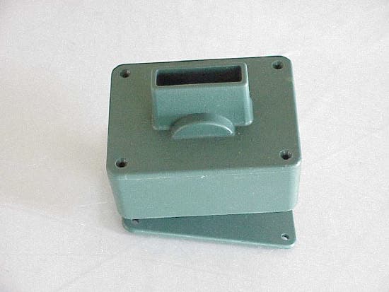
Click to zoom
Application Details
- Equipment Class
- DSC - Part 15 Security/Remote Control Transmitter
- Date of Grant
- Jun 24, 2001
- Application Purpose
- Original Equipment
- Date of Application
- May 03, 2001
- Equipment Note
- Driveway Alert System
- Frequency Range
- 315.00000000 - 315.00000000
- Country
- United States
Documents & Files
Document Text
Text extracted from the exhibit documents filed with the FCC. Open a document above to read the original.
Users Manual
FCCID JLFPIR Angle As Shown Vision Area. Use the Included Silver Tape To Reduce False Alarms To LIMIT the VISION area. Cut and place the tape on the INSIDE of the cover. (Only if unit false alarms). Connecting the Receiver to external devices, such as bells or lights: Receiver(+)Light or Bell N/O (-) COMPower Supply (not Included) (-) (+) New, Updated Feature: The new system you have, includes a new feature. The system will now operate with 4 different transmitters, from 4 different locations on your property. Each transmitter will be identified by a unique “Beep” pattern by the receiver. To add additional PIR transmitters for more coverage of your property, or to protect RVs, Boats or Detached Buildings on your property, call 888-679-7994 and order the PIR Transmitter part# PIR-TX. Each PIR unit costs $49.90 plus S&H. The system will operate with up to 4 different transmitters. Made In USA International Electronics, inc. www.internationalelect.com 12609 NE 95 th St. Suite 106 Vancouver, WA 98682 888-679-7994 360-254-1906 fax 2370 WARRANTY This device has been manufactured in USA with the best quality and workmanship, and is covered by a full One Year Warranty. Warranty covers all defects arising from incidental failures, workmanship, parts failure. Abuse or physical damage is not covered. Defective products can be returned to the address below. MADE IN USA D WA-120 Driveway Alert Installation and Operation Manual The DWA-120 has been designed to detect motion within a set area and wirelessly report it to a receiver, which will generate an alarm. Vinyl Cover, Required! Installation: 5-20 feet Mount 5 Feet from ground 1. Before installing the PIR Motion Sensor Transmitter, TEACH IT TO THE RECEIVER. 1. Plug in the Receiver into the AC transformer. 2. The LED on the Receiver should illuminate, indicating power is OK. 3. Install 4x AAA Batteries into the PIR Transmitter, paying attention to the direction of the batteries. 4. As soon as the last battery is installed, the LED on the PIR PCB should flash twice, indicating proper operation of the PIR unit. 5. Press and HOLD the button on the Receiver marked TEACH. The buzzer will sound. Continue to hold the button. 6. Press and RELEASE the button on top of the PIR transmitter unit once. 7. The receiver should sound to indicate it has learned the transmitter. If that does not happen, repeat steps E-G. 8. Release the TEACH button. 9. To confirm that the receiver has learned the transmitter, press and release the button on top of the PIR Transmitter one time. The receiver will sound to indicate it has received an alarm signal. 2. Mount the PIR Transmitter onto a solid surface, 5 (or more) Feet high and 5-20 feet from the road, as shown. 3. Angle the unit down a bit. 4. Use the included “SILVER TAPE” to limit the vision of the lens as shown on the next page. 5. The unit is waterproof with the cover installed... However, It is best to protect the unit from direct rain or harsh wind. A simple wooden cover, or a cut-out plastic bottle could make a great shelter. 6. SENSITIVITY SETTING: There is a Jumper Shunt inside the unit, marked J1. The unit’s sensitivity is set with this shunt. - Shorted= Very Sensitive. Plastic Plate.. Mount with 2 or 3 Screws, as shown. PIR Transmitter unit. Mount with Window on BOTTOM, as shown. Attach to a surface with screws. Place the screws on the bottom of the bracket ONLY. After attaching the Plastic Bracket, peel the backing from the PIR 2 sided tape and apply to the bracket. Make sure that the unit is mounted so that the cover can slide over it. Do not mount below the screws. Non Metallic Surface Relay Output Teach Button Switches for “Sound Duration” and “Sound Mute” - Open = Normal Sensitivity (Recommended). 7. The unit operates best when mounted so that the Sun does not shine directly onto the lens surface. 8. It is best to mount the unit so that it has no view of the street traffic. 9. If your unit is equipped with an antenna, cut a small hole (1/8”) on the top corner of the vinyl corner (On the back), to slide the antenna through. 10. Slide the COVER over the PIR unit. Make sure that the antenna is protruding from the back of the unit. 11. keep the antenna on the Receiver vertical. Troubleshooting: Problem: The Receiver does not respond to the PIR Transmitter. Solution: a. The units must be “Introduced”. TEACH THE PIR TO THE RECEIVER. See the instructions. b. The Receiver is not powered up. Make sure the LED marked “Power OK” is lit. c. The batteries are dead or not installed properly in the PIR unit. Take the front cover off the PIR unit, and press the “test” button on the top one time. The LED should flash 2 times. d. Check the Dip Switches on the Receiver. Make sure the sound has not been turned off. e. Make sure receiver antenna is vertical, and the units are not out of range. Problem: The PIR does not detect motion consistently. Solution: a. The PIR must be mounted at a proper height of 5 feet or higher. b. The PIR should not be closer than 5 feet from the road. If too close to the road, the faster moving objects like cars may not be detected. c. Angle the PIR , so that it is not “Looking” over or under the moving target. d. There is a “Walk Test LED” inside the PIR unit. It is only visible during the night. During the dark, walking past the PIR unit will illuminate the lens of the PIR, as an indication that the unit has detected motion. e. In cases of detecting cars, face the PIR unit INTO THE ROAD at an angle, so that the PIR can “see” the car for a longer duration of time. See figure A. f. Make sure the batteries are fresh. A low battery will cause inconsistent operation. g. The PIR may be too far from the receiver, or the receiver is near an electronic device, which is interfering with it. h. Reposition the antenna on receiver. PIR Face into road at an angle. Problem: False Alarms. Solution: a. Any of the reasons noted above. b. The PIR should not be looking at the sun. Car’s direction of travel. c. Shelte…
Text truncated - open the document above for the full version.
Block Diagram
FCCID JLFPIR International Electronics, Inc. 3/29/2001 PIR2 Functional Diagram 6v Batteries TEST Switch Functional description: Transmitter: OOK style, low power. Single transistor oscillator, loop “L” antenna. Saw device stabilizes transmit frequency at 315 MHZ. IR Motion Detection: A Dual Port PIR Element detects motion. When the microcontroller detects this motion, it awakens and transmits a code to the receiver. PROCESSOR PIC508 PIR Element 315MHZ TRANSMITTER PCB Loop Antenna LED OPAMP
Cover Letter(s)
Green Mountain Electromagnetics, Inc. GME (802)388-3390 Fax: (802)388-6279 Email: [email protected] 219 Blake Roy Road • Middlebury, VT 05753 6/19/01 Ms. Diane Poole FCC Dear Diane, Enclosed please find the full EMI data set for FCC ID JLFPIR as requested in correspondence number 19648, 731 confirmation number EA100876. Below is the paragraph 231 compliance description. The transmitter is an automatically-operated, motion-detect system which ceases operation in less than 5 seconds. No continuous data transmission occurs and there is no transmission at regular periodic intervals. EMC and occupied-bandwidth compliance is demonstrated in the spectrum analysis in the EMC report and the enclosed data tables. Thank you for your time. Sincerely, Kyle R. Kowalczyk President
External Photos
FCCID JLFPIR
External Photos
FCCID JLFPIR
External Photos
FCCID JLFPIR
ID Label/Location Info
FCC ID tag for PIR-2 Location: Rear of the housing. PIR-2 TRANSMITTER MEETS FCC PART 15 FCCID#: JLFPIR This device complies with FCC part 15 standards. This device may not cause harmful interference to other devices. This device must accept interference, including such which may cause unintended operation. Made In USA
ID Label/Location Info
FCC ID tag for PIR-2 Location: Rear of the housing. PIR-2 TRANSMITTER MEETS FCC PART 15 FCCID: JLFPIR This device complies with FCC part 15 standards. This device may not cause harmful interference to other devices. This device must accept interference, including such which may cause unintended operation. Made In USA
Internal Photos
FCCID JLFPIR
Internal Photos
FCCID JLFPIR
Operational Description
FCCID JLFPIR Angle As Shown Vision Area. Use the Included Silver Tape To Reduce False Alarms To LIMIT the VISION area. Cut and place the tape on the INSIDE of the cover. (Only if unit false alarms). Connecting the Receiver to external devices, such as bells or lights: Receiver(+)Light or Bell N/O (-) COMPower Supply (not Included) (-) (+) New, Updated Feature: The new system you have, includes a new feature. The system will now operate with 4 different transmitters, from 4 different locations on your property. Each transmitter will be identified by a unique “Beep” pattern by the receiver. To add additional PIR transmitters for more coverage of your property, or to protect RVs, Boats or Detached Buildings on your property, call 888-679-7994 and order the PIR Transmitter part# PIR-TX. Each PIR unit costs $49.90 plus S&H. The system will operate with up to 4 different transmitters. Made In USA International Electronics, inc. www.internationalelect.com 12609 NE 95 th St. Suite 106 Vancouver, WA 98682 888-679-7994 360-254-1906 fax 2370 WARRANTY This device has been manufactured in USA with the best quality and workmanship, and is covered by a full One Year Warranty. Warranty covers all defects arising from incidental failures, workmanship, parts failure. Abuse or physical damage is not covered. Defective products can be returned to the address below. MADE IN USA D WA-120 Driveway Alert Installation and Operation Manual The DWA-120 has been designed to detect motion within a set area and wirelessly report it to a receiver, which will generate an alarm. Vinyl Cover, Required! Installation: 5-20 feet Mount 5 Feet from ground 1. Before installing the PIR Motion Sensor Transmitter, TEACH IT TO THE RECEIVER. 1. Plug in the Receiver into the AC transformer. 2. The LED on the Receiver should illuminate, indicating power is OK. 3. Install 4x AAA Batteries into the PIR Transmitter, paying attention to the direction of the batteries. 4. As soon as the last battery is installed, the LED on the PIR PCB should flash twice, indicating proper operation of the PIR unit. 5. Press and HOLD the button on the Receiver marked TEACH. The buzzer will sound. Continue to hold the button. 6. Press and RELEASE the button on top of the PIR transmitter unit once. 7. The receiver should sound to indicate it has learned the transmitter. If that does not happen, repeat steps E-G. 8. Release the TEACH button. 9. To confirm that the receiver has learned the transmitter, press and release the button on top of the PIR Transmitter one time. The receiver will sound to indicate it has received an alarm signal. 2. Mount the PIR Transmitter onto a solid surface, 5 (or more) Feet high and 5-20 feet from the road, as shown. 3. Angle the unit down a bit. 4. Use the included “SILVER TAPE” to limit the vision of the lens as shown on the next page. 5. The unit is waterproof with the cover installed... However, It is best to protect the unit from direct rain or harsh wind. A simple wooden cover, or a cut-out plastic bottle could make a great shelter. 6. SENSITIVITY SETTING: There is a Jumper Shunt inside the unit, marked J1. The unit’s sensitivity is set with this shunt. - Shorted= Very Sensitive. Plastic Plate.. Mount with 2 or 3 Screws, as shown. PIR Transmitter unit. Mount with Window on BOTTOM, as shown. Attach to a surface with screws. Place the screws on the bottom of the bracket ONLY. After attaching the Plastic Bracket, peel the backing from the PIR 2 sided tape and apply to the bracket. Make sure that the unit is mounted so that the cover can slide over it. Do not mount below the screws. Non Metallic Surface Relay Output Teach Button Switches for “Sound Duration” and “Sound Mute” - Open = Normal Sensitivity (Recommended). 7. The unit operates best when mounted so that the Sun does not shine directly onto the lens surface. 8. It is best to mount the unit so that it has no view of the street traffic. 9. If your unit is equipped with an antenna, cut a small hole (1/8”) on the top corner of the vinyl corner (On the back), to slide the antenna through. 10. Slide the COVER over the PIR unit. Make sure that the antenna is protruding from the back of the unit. 11. keep the antenna on the Receiver vertical. Troubleshooting: Problem: The Receiver does not respond to the PIR Transmitter. Solution: a. The units must be “Introduced”. TEACH THE PIR TO THE RECEIVER. See the instructions. b. The Receiver is not powered up. Make sure the LED marked “Power OK” is lit. c. The batteries are dead or not installed properly in the PIR unit. Take the front cover off the PIR unit, and press the “test” button on the top one time. The LED should flash 2 times. d. Check the Dip Switches on the Receiver. Make sure the sound has not been turned off. e. Make sure receiver antenna is vertical, and the units are not out of range. Problem: The PIR does not detect motion consistently. Solution: a. The PIR must be mounted at a proper height of 5 feet or higher. b. The PIR should not be closer than 5 feet from the road. If too close to the road, the faster moving objects like cars may not be detected. c. Angle the PIR , so that it is not “Looking” over or under the moving target. d. There is a “Walk Test LED” inside the PIR unit. It is only visible during the night. During the dark, walking past the PIR unit will illuminate the lens of the PIR, as an indication that the unit has detected motion. e. In cases of detecting cars, face the PIR unit INTO THE ROAD at an angle, so that the PIR can “see” the car for a longer duration of time. See figure A. f. Make sure the batteries are fresh. A low battery will cause inconsistent operation. g. The PIR may be too far from the receiver, or the receiver is near an electronic device, which is interfering with it. h. Reposition the antenna on receiver. PIR Face into road at an angle. Problem: False Alarms. Solution: a. Any of the reasons noted above. b. The PIR should not be looking at the sun. Car’s direction of travel. c. Shelte…
Text truncated - open the document above for the full version.
Schematics
AA BB CC DD EE 4 4 3 3 2 2 1 1 INTERNATIONAL ELEC TRONICS PIR-2 {Doc} A FCCID JLFPIR A 1 2 Tuesday, February 06, 2001 TitleSize Document Number Rev Date: Sheet of D3D4K VCC VCC VCC VCCVCC D1 4148 21 D2 4148 21 + C2 10UF R210K R31MC3 .47UF + C4 10UF R447K R61MR81M R71M C6 0.1UF + C7 100UF D74148 21 DSW1 12 D34148 2 1 D44148 2 1 R9 10K + - IC2A LM324 A 32 1 411 + - IC2BLM324 A 56 7 411 + - IC2CLM324 A 10 9 8 411 + - IC2DLM324 A 1213 14 411 R147K + C1 470UF R16 2.2K C50.047UF R515K PIR1 PIR 321 AA BB CC DD EE 4 4 3 3 2 2 1 1 0.8" 1.05" 0.2" 0.55" {Doc} {RevCode} {Title} A 2 2 Tuesday, February 06, 2001 TitleSize Document Number Rev Date: Sheet of D3D4K VCC VCC VCC VCC VCC TP5 1 R1110K SW1 TP4 1 IC1 276 8 5 1 43 R1447K L1 8UH C90.1UF C100.1UF C1110UF C13470 L2 8UH C140.1UF ANT1ANTENNA R10100K R12330 R15410 DSW2 1 2 R134.7M C80.1UF C125UF TP2 1 TP1 1 TP3 1 D5LED 2 1 D6 21 Y1 OSC8/SM 3 3 OUT 1 4 4 GND 2 Q12N3904 3 1 2
Test Report
Serial No. GM21024f FCC EMC TEST REPORT FOR THE INTERNATIONAL ELECTRONICS, INC. DWA-120 DRIVEWAY ALERT SYSTEM TRANSMITTER FCC ID JLFPIR Prepared for: International Electronics, Inc. 5913-C NE 127 Ave, Suite 800 Vancouver, WA 98682 USA Submitted by: Green Mountain Electromagnetics, Inc. (802) 388-3390 Fax: (802) 388-6279 E-mail: [email protected] 219 Blake Roy Road • Middlebury, Vermont 05753 Copyright: May 3, 2001 This report shall not be reproduced, except in full, without the written approval of GME. FCC ID: JLFPIR Serial No. GM21024f 2 of 11 International Electronics, Inc. FCC EMC Testing At Green Mountain Electromagnetics, Inc. Middlebury, Vermont Unit: DWA-120 Driveway Alert System Transmitter FCC ID JLFPIR Received: 4/26/01 Tested: April 26, 2001 I. Applicable Standards: The unit described in this report was measured for verification of compliance with the FCC Intentional Radiator EMC standard, 47 CFR: Part 15, Subpart C paragraphs 209 & 231. Measurement procedures were in accordance with ANSI C63.4, "Methods of Measurement of Radio-Noise Emissions from Low-Voltage Electrical and Electronic Equipment in the Range of 9 kHz to 40 GHz (1992)." II. Units Tested: The International Electronics, Inc. DWA-120 Driveway Alert System Transmitter provides a signal when the motion-detector circuit is activated. The unit consists of a plastic case containing the transmitter electronics, motion-detector electronics, a permanently attached internal antenna, and a battery. There is no provision for connecting the Transmitter to an AC power source: a conducted emissions test was not performed. The DWA-120 electronics use SAW technology and all assemblies are permanently installed. Device operation was verified with a spectrum analyzer as a receiver. The table below describes the unit that was subjected to measurements determining compliance with applicable EMC standards. ProductManufacturerModelFCCID 315-MHz Low- Power Transmitter International Electronics, Inc. DWA-120 Driveway Alert System JLFPIR FCC ID: JLFPIR Serial No. GM21024f 3 of 11 III. Equipment and Cable Configuration: GME witnessed the unit in satisfactory condition for testing, however the manufacturer is responsible for ensuring that the equipment under test (EUT) represents the product line. The manufacturer is also responsible for the EMC test plan and for assuring that this report is consistent with that plan. The EUT was arranged as in the photographs in Section IX. The EUT configuration produced the maximum radiated emissions. The equipment was subjected to complete emissions tests. A receiver was used to verify transmitter operation during all testing. The equipment was operating in a continuous mode utilizing and testing its control functions. The EUT was also set to self-test upon power up. The temperature, humidity, and atmospheric pressure during testing were 15 ̊C, 31% RH and 100.8 kPa. IV. Measuring Equipment: The table below describes the instrumentation used by Green Mountain Electromagnetics, Inc. (GME) to perform this testing: UnitManufacturerModelSerial #Last Cal.Next Cal. Spectrum Analyzer Hewlett- Packard 85923624A0063112/01/0012/01/01 AmplifierKalmus700A7945-18/18/008/18/01 Pre-amplifierMini-CircuitsZJL-7GD12229811/14/0011/14/01 PlotterHewlett- Packard 7475A2517A05281n/an/a Broadband E-field Antenna Antenna Research Associates LPB-2513/A112510/03/0010/03/01 FCC ID: JLFPIR Serial No. GM21024f 4 of 11 V. Units of Measurement: Measurements of radiated electric fields were made in units of dB referenced to 1 microvolt per meter (dBuV/m). Limits appearing on the spectrum analyzer data were corrected for the appropriate antenna factor, cable loss, amplifier gain and measurement distance X. The following equations were employed: Corrected Limit (dBuV/m) = Limit (dBuV/m) + 20 log(X/3 meters) - Antenna Factor (dB) + (Amplifier Gain (dB) - Cable Loss (dB)). Sample calculation at 30 MHz: 55.0 dBuV corrected limit = 40.0 dBuV/m limit + 20 log(3/3) dB distance - 19.0 dB/m AF + 34.0 dB amp/cable loss. Uncertainty: The combined uncertainties for GME emissions measurements are: u(y) = 1.946 for radiated and u(y) = 1.298 for conducted. VI. Measurement Location: The GME laboratory and Open Area Test Site (OATS) are located at 219 Blake Roy Road, Middlebury, VT. The OATS is a 3-meter site complete with antenna positioner, ground plane and motorized turntable. The OATS is constructed in accordance with ANSI C63.7-1992 and complies with the requirements for radiated emissions testing in ANSI C63.4-1992 and CISPR 16-1993. The electromagnetics laboratory is constructed in accordance with CE immunity standards and ANSI C63.4-1992 (conducted emissions). GME is internationally accredited by the American Association for Laboratory Accreditation (A2LA) and meets the quality requirements in EN 45001-1989 and ISO/IEC Guide 25-1990, "General Requirements for the Competence of Calibration and Testing Laboratories." FCC ID: JLFPIR Serial No. GM21024f 5 of 11 VII. Measurement Procedure: 1. Radiated Emissions in accordance with Part 15.209 & 15.231. Frequency range: 30 MHz to 88 MHz Limit: 40 dBuV @ 3 meters Frequency range: 88 MHz to 216 MHz Limit: 43.5 dBuV @ 3 meters Frequency range: 216 MHz to 960 MHz Limit: 46 dBuV @ 3 meters Frequency range: 960 MHz to 3.1 GHz Limit: 54 dBuV @ 3 meters Fundamental frequency: 315 MHz Limit: 73.9 dBuV average/93.9 dBuV peak @ 3 meters Harmonic frequencies: 630, 945, 1260, 1575, 1890, 2205, 2520, 2835, 3150 MHz Limit: 61.9 dBuV @ 3 meters a.Set up instrumentation at open area test site. i. Mount EUT on table and broadband antenna on antenna positioner. ii. Record temperature, humidity and atmospheric pressure. iii. Measurement distance is 3 meters and antenna scan height is varied from 1 to 4 meters. b.Verify spectrum analyzer and antenna operation. i. Spectrum analyzer is connected to antenna. ii. Preamplifier is inserted between antenna and analyzer to ensure analyzer noise threshold is at least 6 dB below speci…
Text truncated - open the document above for the full version.
Test Report
Radiated Emissions Data - FCCID JLFPIR Page 1 of 1 FreqPolDetectorRBWVBWVmeasAFAmpCableFieldDistLimitDev MHzH/VkHzkHzdBuVdB1/mdBdBdBuV/mdBdBuV/mdB 30HPeak120300401935125040-15 30VPeak120300391935124040-16 35HPeak1203004818.235132.2040-7.8 35VPeak1203005018.235134.2040-5.8 40HPeak1203004418.335128.3040-11.7 40VPeak1203004618.335130.3040-9.7 45HPeak1203004517.835128.8040-11.2 45VPeak1203004617.835129.8040-10.2 50HPeak1203003915.635221.6040-18.4 50VPeak1203004015.635222.6040-17.4 60HPeak120300501135228040-12 60VPeak120300471135225040-15 70HPeak12030053835228040-12 70VPeak12030051835226040-14 80HPeak120300529.835228.8040-11.2 80VPeak120300449.835220.8040-19.2 90HPeak1203004510.935222.9043.5-20.6 90VPeak1203004110.935218.9043.5-24.6 100HPeak12030043.512.535324043.5-19.5 Radiated Emissions Data - FCCID JLFPIR Page 2 of 2 FreqPolDetectorRBWVBWVmeasAFAmpCableFieldDistLimitDev MHzH/VkHzkHzdBuVdB1/mdBdBdBuV/mdBdBuV/mdB 100VPeak1203004312.535323.5043.5-20 125HPeak12030043.512.235323.7043.5-19.8 125VPeak1203004212.235322.2043.5-21.3 150HPeak12030043.510.535423043.5-20.5 150VPeak1203004310.535422.5043.5-21 175HPeak1203004410.935423.9043.5-19.6 175VPeak1203004510.935424.9043.5-18.6 200HPeak1203004611.335426.3043.5-17.2 200VPeak1203004311.335423.3043.5-20.2 250HPeak1203003813.435420.4046-25.6 250VPeak1203003913.435421.4046-24.6 300HPeak1203004115.135425.1046-20.9 300HPeak1203004115.135425.1046-20.9 315HPeak1203007815.135462.1074-11.9 315HPeak1203007915.135463.1074-10.9 400HPeak1203004316.5354.529046-17 400VPeak1203004216.5354.528046-18 500HPeak1203004618.235534.2046-11.8 500VPeak1203004518.235533.2046-12.8 Radiated Emissions Data - FCCID JLFPIR Page 3 of 3 FreqPolDetectorRBWVBWVmeasAFAmpCableFieldDistLimitDev MHzH/VkHzkHzdBuVdB1/mdBdBdBuV/mdBdBuV/mdB 600HPeak1203004019.735529.7046-16.3 600VPeak1203004319.735532.7046-13.3 630HPeak12030070.519.735560.2046-1.7 630VPeak12030071.519.735561.2046-0.7 700HPeak1203004420.2355.534.7046-11.3 700VPeak1203004320.2355.533.7046-12.3 800HPeak1203003821.534631.5046-14.5 800VPeak1203003921.534632.5046-13.5 900HPeak1203003822.434632.4046-13.6 900VPeak1203003922.434633.4046-12.6 945HPeak1203004422.434638.4046-7.6 945VPeak1203004322.434637.4046-8.6 959HPeak1203003722.433733.4046-12.6 959VPeak1203003922.433735.4046-10.6 960HPeak1203003822.433734.4046-11.6 960VPeak1203003722.433733.4046-12.6 1000HPeak100010003024.29146.2054-7.8 1000VPeak100010003124.29147.2054-6.8 1260HPeak100010003324.2101.348.5054-5.5 Radiated Emissions Data - FCCID JLFPIR Page 4 of 4 FreqPolDetectorRBWVBWVmeasAFAmpCableFieldDistLimitDev MHzH/VkHzkHzdBuVdB1/mdBdBdBuV/mdBdBuV/mdB 1260VPeak100010003424.2101.349.5054-4.5 1575HPeak100010003124.2101.546.7054-7.3 1575VPeak100010003024.2101.545.7054-8.3 1890HPeak100010003126.89.61.549.7054-4.3 1890VPeak100010003126.89.61.549.7054-4.3 2205HPeak100010003226.89.31.5511054-13 2205VPeak100010003026.89.31.5491054-15 2520HPeak100010002926.891.548.31054-15.7 2520VPeak100010003026.891.549.31054-14.7 2835HPeak100010002830.191.850.91054-13.1 2835HPeak100010002730.191.849.91054-14.1 3150HPeak100010002831.292.552.71054-11.3 3150HPeak100010002731.292.551.71054-12.3
Test Setup Photos
FF FCCID JLFPIR
Contact Information
Applicant
Barbara Kelkhoff(Manager of Regulatory Affairs)
Test Firm
Green Mountain ElectromagneticsKyle Kowalczyk
Technical Specifications
| # | Rule Parts | Frequency Range | Power Output |
|---|---|---|---|
| 1 | 15C | 315 MHz - 315 MHz | - |
Other Applications from Chamberlain Wireless Products Inc.
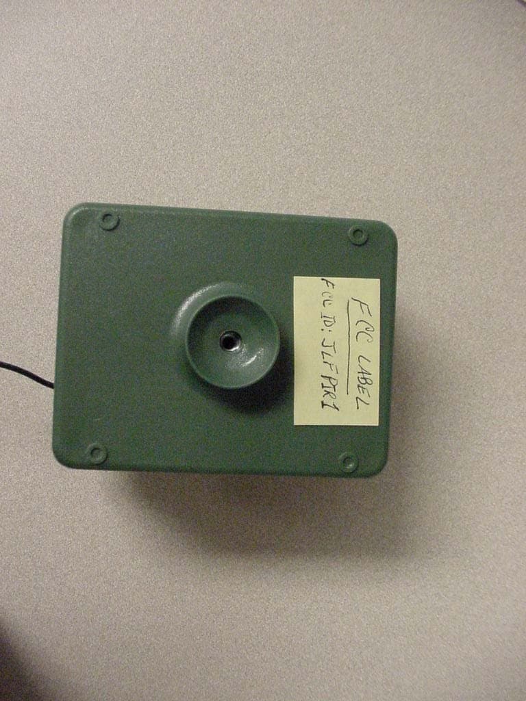
JLFPIR1
Mar 31, 2008Remote Control Device
Equipment Class
DSC - Part 15 Security/Remote Control Transmitter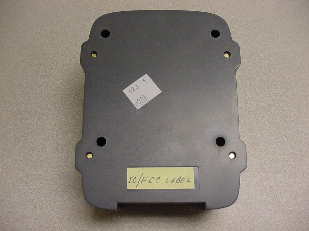
JLFOPB2
Mar 12, 20083 Button Push to Exit
Equipment Class
DXX - Part 15 Low Power Communication Device Transmitter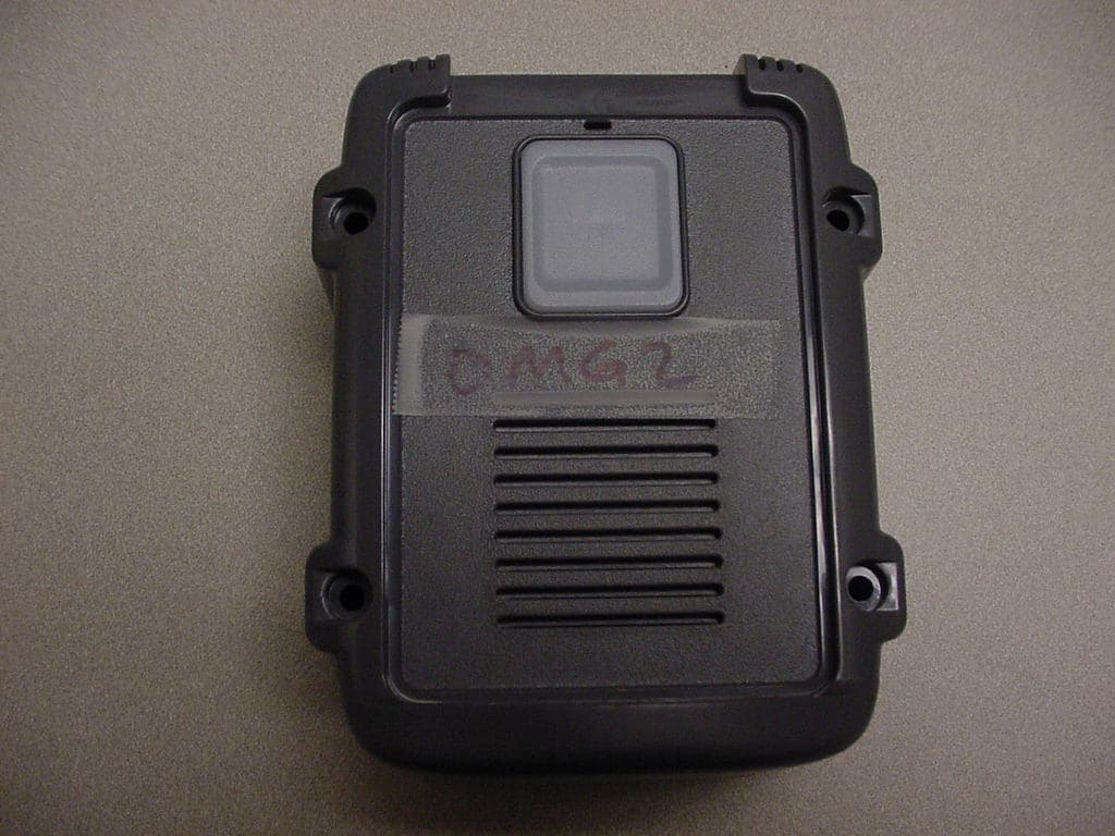
JLFOMG1
Mar 12, 2008Gate Access System
Equipment Class
DXX - Part 15 Low Power Communication Device Transmitter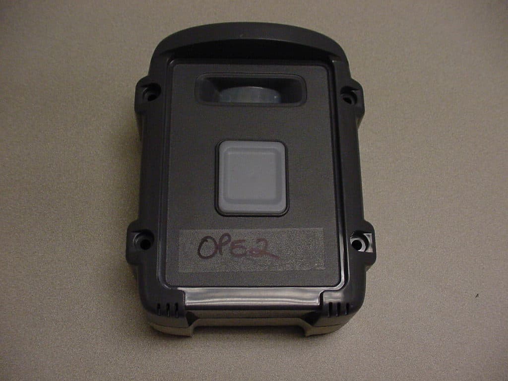
JLFPTE2
Mar 12, 2008Push to Exit
Equipment Class
DSC - Part 15 Security/Remote Control Transmitter
JLFKPD1
Jan 02, 2008Wireless Keypad Interface
Equipment Class
DXX - Part 15 Low Power Communication Device Transmitter